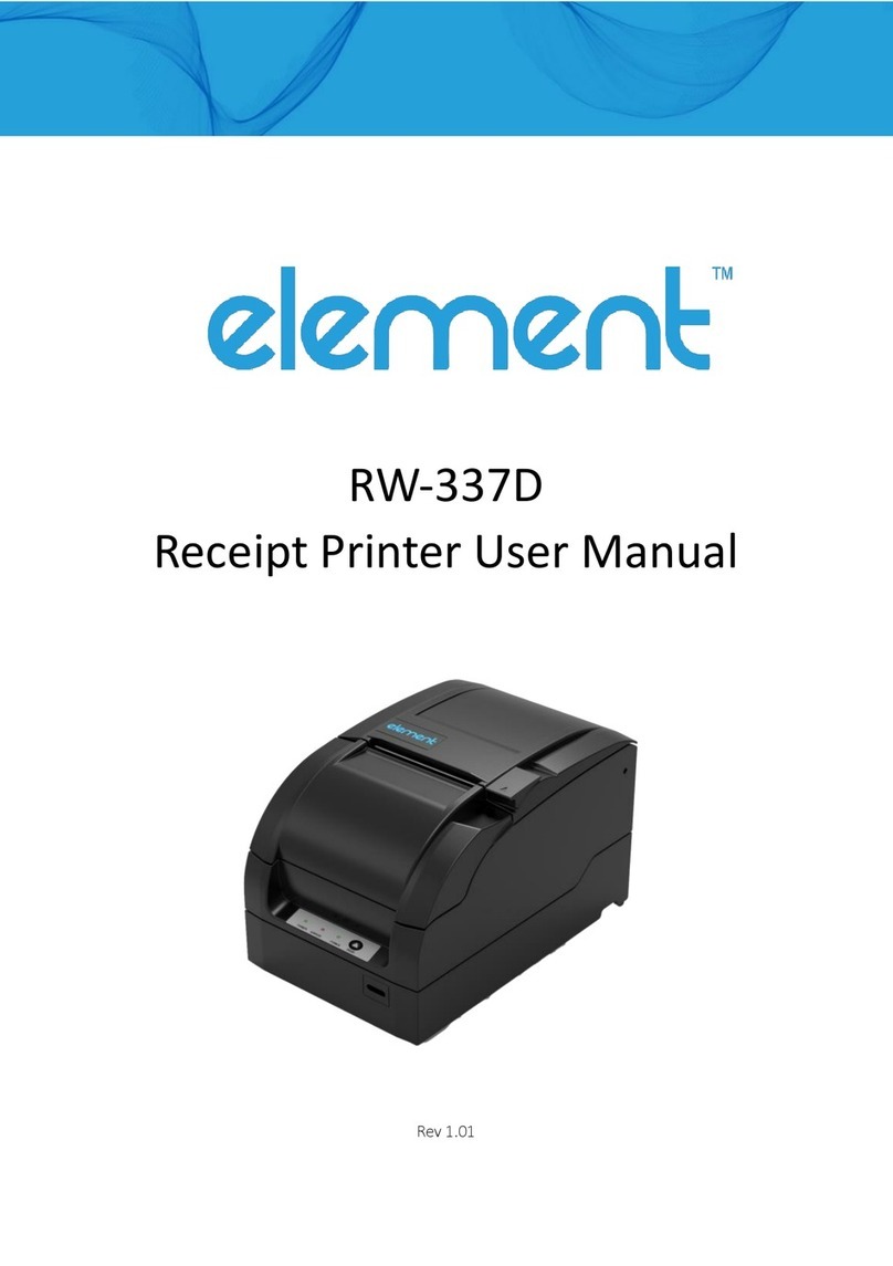
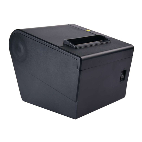
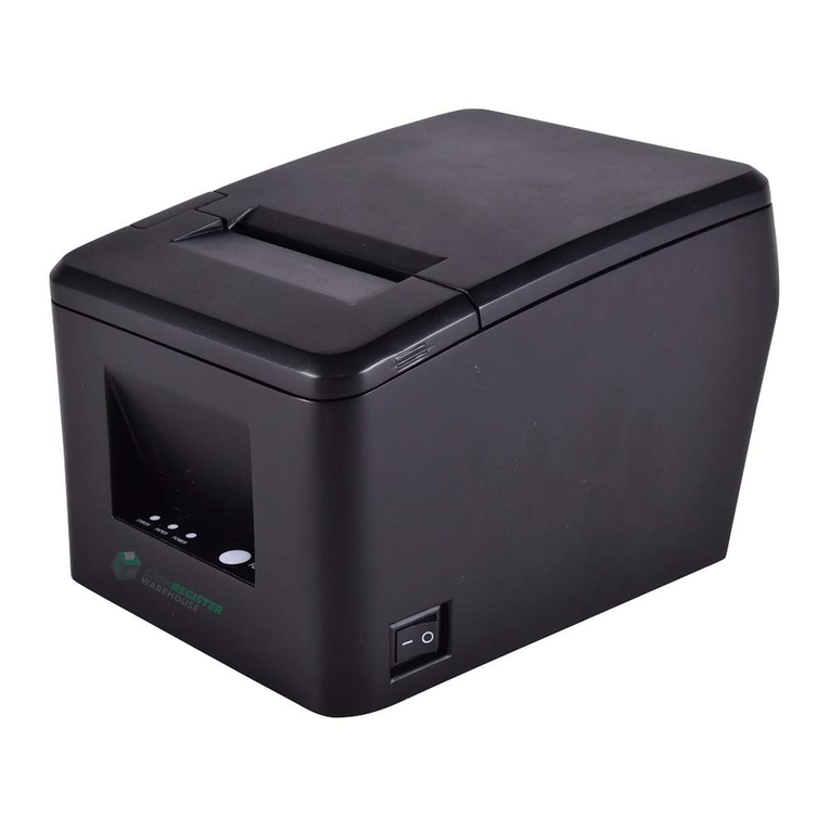
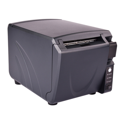
Element RW-337D User manual

RW-337D Service Manual I Page 1of 61
RW-337D
Receipt Printer Service Manual

RW-337D Service Manual I Page 2of 61
Declaration
Information in this document is subject to change without notice. Element LTD. (hereinafter referred to as
“element”) reserves the right to improve product as new technology, components, software, and firmware become
available. If users need further data about this product or have any doubt about safety issues that might arise from
using it, please feel free to contact your dealer.
No part of this document may be reproduced or transmitted in any form or by any means, electronic or mechanical,
for any purpose without the express written permission of element.
Copyright
Copyright © 2021 by Element.
Warning and Caution
Warning: Items shall be strictly followed to avoid damages to body and equipment.
Caution: Items with important information and prompts for operating the printer.

RW-337D Service Manual I Page 3of 61
Maintenance cautions
1) Follow the steps in this manual during maintenance;
2) Make sure that the printer and the computer are turned off before plugging/unplugging the communication
cable, changing print head or doing maintenance to the printer;
3) Be sure to protect it against electrostatic damage when maintaining print head and other electronic
components;
4) Time between turning on and turning off the printer should be no less than 20 seconds;
5) Do not print without paper and ribbon; otherwise you may damage the print bar and print head;
6) In order to ensure the stable work of each components and printer’s lifetime, you need to conduct a regular
maintenance monthly at least. The regular maintenance includes printer status check, printer dust cleaning
and part lubrication. If the printer has a larger workload, the maintenance cycle can be appropriately
shortened.

RW-337D Service Manual I Page 4of 61
Contents
1 Features and Specifications ...........................................................................................................................................1
1.1 Features..................................................................................................................................................................1
1.2 Technical Specifications..........................................................................................................................................1
2 Printer Overview ............................................................................................................................................................2
3 Main Control Board Description ....................................................................................................................................4
3.1 USB interface..........................................................................................................................................................4
3.1.1 Parameter .......................................................................................................................................................4
3.1.2 Interface signal................................................................................................................................................4
3.1.3 USB interface connection...............................................................................................................................4
3.2 Serial interface........................................................................................................................................................4
3.2.1 Parameter .......................................................................................................................................................4
3.2.2 Interface connection and signal function.......................................................................................................5
3.2.3 Serial connection ............................................................................................................................................5
3.3 Parallel interface.....................................................................................................................................................5
3.3.1 Parameter .......................................................................................................................................................5
3.3.2 Time Sequence of the Parallel Interface Module ..........................................................................................5
3.3.3 Interface signal................................................................................................................................................6
3.3.4 Parameter .......................................................................................................................................................7
3.3.5 Effect of printer’s status on parallel interface ...............................................................................................7
3.4 Ethernet interface...................................................................................................................................................7
3.4.1 Interface character .........................................................................................................................................7
3.4.2 Protocol supported.........................................................................................................................................7
3.4.3 Electrical character .........................................................................................................................................8
3.4.4 Frame type......................................................................................................................................................8
3.4.5 Interface signal................................................................................................................................................8
4 Disassembly and Assembly............................................................................................................................................9
4.1 Maintenance Tools .................................................................................................................................................9
4.2 Disassemble the printer .......................................................................................................................................10
4.2.1 Disassemble the printer cover......................................................................................................................10
4.2.2 Disassemble the main control board cover .................................................................................................13

RW-337D Service Manual I Page 5of 61
4.2.3 Disassemble the stationary blade cutter module........................................................................................14
4.2.4 Disassemble the non-retraction platen roller module ................................................................................15
4.2.5 Disassemble the paper cabinet module.......................................................................................................17
4.2.6 Disassemble the print module......................................................................................................................20
4.3 Assemble the printer............................................................................................................................................24
5 Printer maintenance ....................................................................................................................................................25
5.1 Main part replacement ........................................................................................................................................25
5.1.1 Print head replacement................................................................................................................................25
5.1.2 Cutter replacement ......................................................................................................................................26
5.1.3 Main control board replacement.................................................................................................................28
5.1.4 Paper feed motor replacement....................................................................................................................28
5.1.5 CR motor replacement .................................................................................................................................29
5.1.6 Upper mark sensor replacement..................................................................................................................30
5.1.7 Lower mark sensor replacement..................................................................................................................31
5.1.8 HP sensor replacement.................................................................................................................................32
5.1.9 Paper sensor replacement............................................................................................................................32
5.2 Printer adjustment ...............................................................................................................................................33
5.2.1 Print spacing adjustment..............................................................................................................................33
5.2.2 Tighten transmission belt of carriage...........................................................................................................34
6 Error Types and Processing..........................................................................................................................................35
7 Troubleshooting ...........................................................................................................................................................36
7.1 Abnormal print effect...........................................................................................................................................36
7.2 Abnormal paper detection...................................................................................................................................36
7.3 Printing with noise................................................................................................................................................36
7.4 Abnormal ribbon action .......................................................................................................................................37
7.5 Abnormal cutter action ........................................................................................................................................37
7.6 Printer doesn’t work.............................................................................................................................................38
7.7 Problem during the printing process ...................................................................................................................38
Appendix .........................................................................................................................................................................39
Appendix 1 Hexadecimal Dump Mode.......................................................................................................................39
Appendix 2 Command list ..........................................................................................................................................40
Appendix 3 EEPROM setting table .............................................................................................................................42
Appendix 4 Spare part list ..........................................................................................................................................43
RW-337D Service Manual I Page 6of 61
Appendix 5 Exploded drawing of the printer.............................................................................................................46
Appendix 6 Part list.....................................................................................................................................................49
Appendix 7 Outline drawing.......................................................................................................................................53
Appendix 8 Main board layout...................................................................................................................................54
Appendix 9 Lubrication...............................................................................................................................................55

RW-337D Service Manual I Page 1of 61
1 Features and Specifications
1.1 Features
The RW-337D is a 9-pin serial impact dot matrix receipt printer offering high quality, high speed, and stable
performance. It is widely used in real-time printing on-site, such as POS system, kitchen and finance applications.
The RW-337D can be connected with other devices via USB, parallel, serial and Ethernet interface, and it provides
drivers and applications under 2000/2003/XP/Vista.
1.2 Technical Specifications
Item
Specifications
Print mode
9-pin serial impact dot matrix
Print speed
Max. 4.7LPS (400 dots/line)
Print width
Max. 400(half dots)/200(full dots)
Paper
Paper type
Continuous paper or marked paper
Single layer
Paper width: 80±0.5mm,76±0.5mm,69.5±0.5mm,57.5±0.5mm;
Paper thickness: 0.06—0.085mm
Multi-layer paper
(1 original+1 copies)
Paper width: 80±0.5mm,76±0.5mm,69.5±0.5mm,57.5±0.5mm;
Paper thickness: 0.05—0.08mm, total thickness≤0.14 mm
Character
Character type
Font A: 9×9 Font B: 7×9 Chinese: 16×16
Characters/line (Default)
76mm
69.5mm
57.5mm
Font A
33 CPL
30 CPL
25 CPL
Font B
40 CPL
36 CPL
30 CPL
Chinese
22 CPL
20 CPL
16 CPL
Character size (Default)
Font A: 1.6×3.1mm Font B: 1.2×3.1mm Chinese: 2.7×2.9mm
Characters/inch (Default)
Font A: 13.3CPI Font B: 16CPI Chinese: 8.9CPI
Data
buffer
Receiving buffer
64KB/8KB/40Byte
NV image data
128KB
NV user data
8KB
Ribbon specification
ERC-38 ribbon cartridge
Ribbon lifetime
ERC-38(P)
4,000,000 characters
ERC-38(B)
3,000,000 characters
ERC-38(B/R)
Black: 1,500,000 characters
Red: 750,000 characters
Communication interface
USB / IEEE1284/RS-232/Ethernet /(optional)
Cash drawer connector
Can control 1~2 cash drawers
Power supply
AC100-240V~1.0A Max 50-60Hz
Reliability
Printing Mechanism
10,000,000 lines
Print head
150,000,000 characters
Cutter
800,000 cuts(paper thickness:0.080mm, standard testing condition)
Operating temperature and humidity
5~45℃,20~90%RH (40℃)
Storage temperature and humidity
-40~60℃,20%~93%RH (40℃)
Dimensions
160(W)×245(D)×154(H)
Weight
3.0kg

RW-337D Service Manual I Page 2of 61
2 Printer Overview
The RW-337D printer consists of the following parts:
Pinter mechanism part, NDLF main control board, expanded interface board.
Main control board unit block diagram is shown as below:
CPU
FLASH
Communication interface
module
Communication interface
module STY_HHEAD
Print head drive
circuit
Power
input
interface
COV2 COV1 BM2 PE BM1
PLOW
1
PLOW
2HP
CN500
MOTO1 KEY_LED
1
MOTO2
Power
switch
Cutter drive
circuit
Motor drive
circuit
Printer
mechanism
Communication
interface module
Host
Host
Communication
interface module
Main Control Board Unit Block Diagram

RW-337D Service Manual I Page 3of 61
Position of all the sockets in the main control board

RW-337D Service Manual I Page 4of 61
3 Main Control Board Description
RW-337D can be connected to another device with USB, serial, parallel, Ethernet or WIFI interface.
3.1 USB interface
3.1.1 Parameter
➢Data transfer: Supports USB1.1 Protocol
➢Connector: USB B type standard socket
3.1.2 Interface signal
The printer built-in USB interface supports USB1.1 protocol, of which the outlet is USB A type.
Interface signal is defined as below:
3.1.3 USB interface connection
Host Printer
VBUS..................................…VBUS
DATA- ................................…DATA-
DATA+................................... DATA+
GND .......................................GND
Caution:
The vertical USB interface cannot be used when set the receiving buffer to 40Bytes.
3.2 Serial interface
3.2.1 Parameter
➢Data transmission: Asynchronous serial communicate
➢Handshaking: DTR/DSR or XON/XOFF
➢Voltage: MARK = -3 to -15V: Logic "1"/ OFF
SPACE = +3 to +15V: Logic "0"/ ON
➢Baud rate: 1200, 2400, 4800, 9600, 19200, 38400, 57600 bps
[bps: bits per second]
➢Data bit: 7 bit or 8 bit
➢Parity bits: No
➢Stop bit: 1 bit or 2 bit
➢Connector: D-SUB 25PIN hole socket
Caution:
Handshaking, baud rate, data bit and stop bit can be set by EEPROM and feed button.
Pin
Signal name
Function
1
VBUS
+5V
2
DATA-
Data-
3
DATA+
Data+
4
GND
Ground

RW-337D Service Manual I Page 5of 61
3.2.2 Interface connection and signal function
Pin
Signal Name
Signal Direction
Function
1
FG
—
Frame ground
2
TXD
OUTPUT
Data output
3
RXD
INPUT
Data input
4
RTS
OUTPUT
Request to send
6
DSR
INPUT
Host ready
7
SG
—
Signal ready
20
DTR
OUTPUT
Data terminal ready
3.2.3 Serial connection
Host Printer
TXD---------------RXD
RXD---------------TXD
DSR---------------DTR
CTS---------------RTS
RTS---------------CTS
DTR---------------DSR
FG -----------------FG
SG ----------------SG
3.3 Parallel interface
Parallel interface works under IEEE1284 compatible mode and byte mode.
3.3.1 Parameter
➢Data transmission: 8 bit parallel
➢Synchronized mode: Externally supplied nStrobe signals
➢Handshaking mode: Busy Signal
➢Handshaking pressure: TTL compatible
➢Connector: IEEE 1284-B(CENTRONICS) socket
3.3.2 Time Sequence of the Parallel Interface Module
Time Sequence of Parallel Interface (compatible mode)

RW-337D Service Manual I Page 6of 61
Signal
Min. value (ns)
Max. value (ns)
tSetup
750
-
tReady
0
-
tStb
750
-
tBusy
0
500
tHold
750
-
Time Request of Parallel Interface
3.3.3 Interface signal
Pin
Signal source
Signal definition
Pin
Signal source
Signal definition
1
H
nStrobe
19
Signal Ground
2
H
Data 0 (Least Significant Bit)
20
Signal Ground
3
H
Data 1
21
Signal Ground
4
H
Data 2
22
Signal Ground
5
H
Data 3
23
Signal Ground
6
H
Data 4
24
Signal Ground
7
H
Data 5
25
Signal Ground
8
H
Data 6
26
Signal Ground
9
H
Data 7 (Most Significant Bit)
27
Signal Ground
10
P
Ack
28
Signal Ground
11
P
Busy
29
Signal Ground
12
P
PError
30
Signal Ground
13
P
Select
31
H
nInit
14
H
nAutoLF
32
P
nFault
15
Not defined
33
Signal Ground
16
Logic Gnd
34
Not defined
17
Chassis Gnd
35
Not defined
18
P
Peripheral Logic High
36
H
nSelectIn
Parallel interface signal definition
Caution:
H stands for host end, P stands for printer end.
Parallel interface signal adopting TTL level. Please make sure that both ascending and descending time of the
host end are less than 0.5s when using the printer to print.
During data transmitting, the host end should not neglect the Busy signal, otherwise the printing data will be
lost.
The parallel interface signal cable should be as short as possible.

RW-337D Service Manual I Page 7of 61
3.3.4 Parameter
3.3.5 Effect of printer’s status on parallel interface
Status
/nFault
PE
Normal status
High
Low
Paper end
Low
High
Rear cover open
Low
Low
Cutter error
Low
Low
Input voltage is abnormal
Low
Low
Print head is overheated
Low
Low
HP error
Low
Low
Caution:
When the above error occurs, user can inquire the printer’s status from the pin of parallel interface.
3.4 Ethernet interface
3.4.1 Interface character
➢Supports 10BASE-T communication
➢Ethernet II frame type compatible
➢LED indicates the net connection status and data transmission status
➢Supports 9100 port printing
➢Supports status back
➢Supports parameter configuration
➢Supports firmware update online
➢Supports printer status inquiry and interface module maintenance based in HTTP mode
3.4.2 Protocol supported
➢IP
➢ARP
➢ICMP
➢TCP

RW-337D Service Manual I Page 8of 61
➢UDP
➢DHCP
➢TFTP
➢HTTP
3.4.3 Electrical character
Output signal:
➢The valid differential mode voltage is more than 450mV, and the peak voltage is no more than 13V;
➢The common mode peak AC voltage is no more than 2.5V.
Input signal:
➢If the differential mode voltage is more than 160mV, then it is valid signal.
3.4.4 Frame type
Compatible with the frame type of Ethernet II format.
3.4.5 Interface signal
The interface use 10BASE-T standard which comply to IEEE802.3.
Pin
Signal Name
Description
1
TX+
Data sending +
2
TX-
Data sending-
3
RX+
Data receiving+
4
NC
Reserved
5
NC
Reserved
6
RX-
Data receiving-
7
NC
Reserved
8
NC
Reserved

RW-337D Service Manual I Page 9of 61
4 Disassembly and Assembly
Caution:
Do not disassemble, assemble or adjust the printer if it works properly. Do not unscrew any screws
unless necessary.
When disassembling and assembling, avoid damaging all wires and cables.
When handling the print head or electronic component, make sure to take some measures to protect it
from electrostatic charge.
During maintenance, be careful not to leave parts or screws loose inside the printer.
During maintenance, be careful not to damage the print head surface and the print bar.
4.1 Maintenance Tools
Maintenance Tools:
➢Cross screwdriver
➢Sharp-nose pliers
➢Wire cutter
Assistant materials:
➢Lubricant grease
➢Alcohol
➢Absorbent cotton

RW-337D Service Manual I Page 10 of 61
4.2 Disassemble the printer
4.2.1 Disassemble the printer cover
Picture
Instructions
Top view of printer.
1) Remove the two screws (ST2.9x8) shown in the
figure with the cross screwdriver;
2) Take off the vertical pluggable interface board
shown in the figure.
1) Push out the power cover plate in the arrow
direction;
2) Take off the built-in power supply from its
location position.

RW-337D Service Manual I Page 11 of 61
Remove the six screws (M3x4) shown in the figure with
cross screwdriver, and take off the bottom cover.
1) Remove the four screws (ST2.9x6) shown in the
figure with cross screwdriver;
2) Take off the top cover.
Remove the four screws (ST2.9x6) shown in the figure
with cross screwdriver, and take off the front cover.

RW-337D Service Manual I Page 12 of 61
1) Remove the two screws (M3x7) shown in the
figure with cross screwdriver;
2) Disconnect the connecting cable between button
and control board;
3) Push out the cover locking unit at the back of
middle cover with appropriate force, and take off
the middle cover;
4) Take off the baffle of middle cover with
appropriate force upward.
Notes:
Please do not pull the connection wire to avoid
damage to the wire when plug and unplug the
connection wire
Remove the two screws (ST2.9x6) shown in the figure
with cross screwdriver, and take off the button board.

RW-337D Service Manual I Page 13 of 61
4.2.2 Disassemble the main control board cover
Picture
Instructions
Remove the two screws (M2.5x5) shown in the figure
with cross screwdriver, and take off the optional
communication interface module.
Notes:
Please use moderate force to plug/unplug the
communication interface in horizontal direction to
avoid damaging the pins.
1) Unplug all the wires in the main control board
with a moderate force;
2) Remove the four screws (M3x5) with the screw
driver and take off the main control board.
Notes:
Please keep the main control board safely to avoid
scratching and short circuit;
Please do not pull the connection wire to avoid
damage to the wire when plug and unplug the
connection wire.
1) Remove the two screws (M2x8) shown in the
figure at ① with cross screwdriver and take off
the micro switch;
2) Remove the two sunk screws (M3x5) shown in the
figure at ② with cross screw driver and take off
the guide plate;
3) Take off the power switch in the arrow direction
shown in the figure

RW-337D Service Manual I Page 14 of 61
Remove the three screws (M3x5) shown in the figure
with cross screwdriver and take off the interface plate
in the arrow direction shown in the figure.
4.2.3 Disassemble the stationary blade cutter module
Picture
Instructions
Take off the one "E"-ring on one end of the rotation
shaft of stationary blade cutter with sharp-nose pliers,
pull out the rotation shaft of stationary blade along the
arrow direction and disassemble the stationary blade
module
Remove the two screws (M3x7) shown in the figure
with cross screwdriver, and take off the cutter bracket
and stationary blade cutter
Notes:
Please be careful to keep the stationary blade
disassembled to avoid damage to human body;
Please be careful to keep the stationary blade
disassembled to avoid being scratched by hard
objects.
Other manuals for RW-337D
2
Table of contents
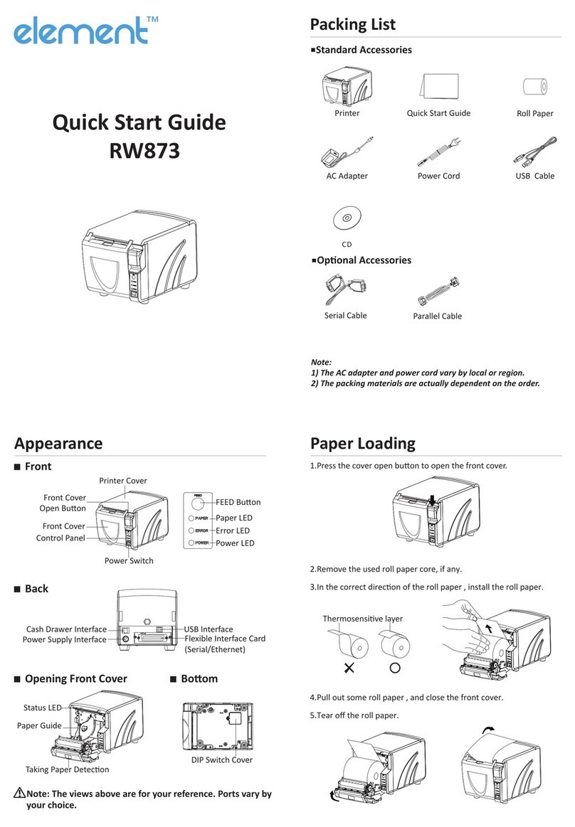
Other Element Printer manuals

Element
Element RW-337D User manual

Element
Element RW873 User manual

Element
Element RW973 Mk2 User manual

Element
Element RW-337D User manual

Element
Element RW873 User manual

Element
Element RW80L User manual

Element
Element POS80D User manual

Element
Element RW973 User manual

Element
Element RW973 Installation and operation manual

Element
Element RW60 User manual