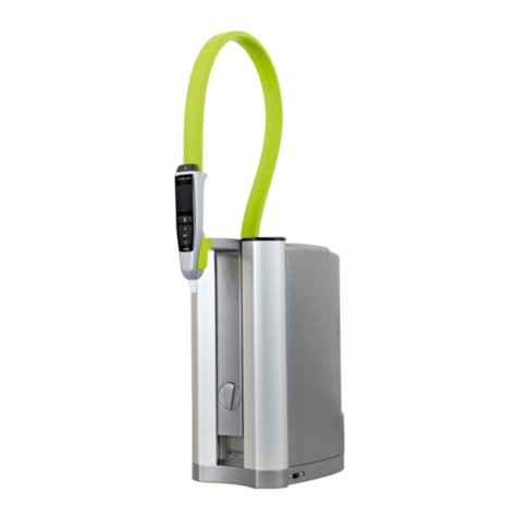
ELGA Elgastat Option 4 Series Service manual


ThisOperatorsManualhasbeenpreparedforthe
ELGASTATOPTION4
rangeofwaterpurificationunitsandappliestothefollowingmodels:
ElgastatOption4A
ElgastatOption4B
220/240V50Hz
110/120V60Hz
90/110V60HZ
Themanualcontainsfulldetailsoninstallation,commissioningandoperationoftheunit
purchased.
Ifhowever,youhaveanyqueriespleasecontactyourlocaldistributororElga
ServiceDivisionwhowillbepleasedtodealwithyourenquiry.
LocalDistributorElgaServiceDivision
LaneEnd
HighWycombe
BucksHP143JH
Tel:
(01494)881393
Fax:(01494)881007

TableofContents
1.
HEALTHANDSAFETYNOTES1
2.
PRODUCTDESCRIPTION2
3.ELGASTATOPTION- TECHNICALSPECIFICATIONS4
4.
PROCESSDESCRIPTION6
5.INSTALLATIONINSTRUCTIONS8
5.1.
ServiceConnections8
5.2.Unpacking8
5.3.Installation9
5.4.RemoteLevelControlFacility10.
5.5.Table1 ElgastatOption4 ReverseOsmosisCapacityCalculations13
6.START-UPPROCEDURE14
6.1.
Start-UpProcedureforOption4 units14
7.FITTINGREPLACEMENTCARTRIDGE1:8
7.1.
ReplacingtheLC101Pre-treatmentcartridge...;18
7.2.ReplacementofLC102ReverseOsmosisCartridge....;.;: 20
7.3.ReplacingLC117Dlcartridgepack22
7.4.ReplacingLC105UltravioletLamp.-.
7.5.ReplacingtheLC106PointofUsefilter:
8.CLEANINGPROCEDURE,*,
8.1.
Cleaning/SanitisationProcedure] 25
9.CONSUMABLES, 27
9.1.
Accessories) 27
Opt4 Issue2-05/93

1.HEALTHANDSAFETYNOTES
TheElgastatrangeofproductshavebeendesignedwithsafetyinmind,howeveritisimportant
thatpersonnelworkingontheseunitsarefamiliarwithanypotentialdangers.Themostlikely
sourceofhazardsareasfollows:
1.
Electricity
Thoseproductsrequiringelectricalsuppliesoperateatmainssupplyvoltages.Itis
essentialthattheelectricalsupplyisisolatedbeforeanyworkisstarted.Forroutine
operationssuchaschangingtheDlcartridgepackandPretreatmentcartridgesitis
sufficienttoswitchtheunitoffatthepowerinletmodulelocatedatthetoprearlefthand
side.
Formoredetailedworkoraccesstotheprintedcircuitboardstheunitmustbe
physicallydisconnectedfromthemainssupplybyremovalofthemainsfeed
plug.
2.
Pressure
Mainsfeedwaterpressureortheinternalrecirculationpumpareusedtopumpthewater
throughthevariousstagesofpurification.Thispressurecouldpresenta dangerifnot
dissipatedpriortochangingcartridgesetc.Itisessentialthatthemainspressureis
isolatedandresidualpressureisallowedtodissipatepriortoremovalofanycartridges.
Switchingofftheelectricitywillisolatethesourceofpressureonthoseunitsrequiring
anelectricalsupply.Onthoseunitwithoutrequirementforelectricitythewaterpressure
shouldbeisolatedfromthemainswatersupply.
3.Ultra-VioletLight
Onsomeunitsshortwavelengthultra-violetlightisusedtodestroymicro-organisms.
Thebluelightvisiblefromthefrontoftheunitisquitesafeastheharmfulcomponentof
theultra-violetisfilteredout.Howevertheunitshouldnevertooperatedwiththefront
coverremovedastheoperatorcouldbeexposedtosorneshortwavelengthUVlight.
4.
Chemicals
Cleaningusingspecialistchemicalsisrecommendedonsomeunits.Safetydatasheets
conformingtoCOSHHregulationswillbesuppliedwithanychemicalsandtheseshould
becloselyfollowed.
Pleaseensurethatyouandanyotherstaffworkingontheseproductsarefamiliarwith
thepotentialdangersandthatthepropersafetyequipmentisavailable.Ifindoubt
contactyoulocaldistributorortheElgaServiceDivision.
5.ControlofSubstancesHazardous(COSHH)
Materialsafetydatasheetscoveringthevariousreplaceablecartridgesareavailable
uponrequestifyoucontactyourlocaldistributorortheElgaServiceDivision.
Opt4 Issue2-05/93

2.
PRODUCTDESCRIPTION
TheElgastatOption
4
waterpurificationunithasbeenspecificallydesigned
to
producepurified
waterequivalent
in
quality
to
waterprepared
by
distillation
but
without
the
highenergycosts
associatedwithdistillation.
Thehighelectricalrunningcostsnecessitated
bythe
phasechangewhichtakesplaceduring
distillation
has
longbeenrecognized
asa
major,
ifnot
sometimeshiddendisadvantage
of
usingthistechnique
forthe
production
of
purifiedwater.Additionallypretreatment
is
often
required
to
protect
the
stillfromscaling.
TheElgastatOption
4
wasdesignedwiththesepoints
in
mindandachievesbetterwaterquality
than
is
availablefromdistillationequipmentwhile
atthe
sametimerequiring
no
energy
requirement
inthe
form
of
heating.
The
latestmembranetechnology
is
employed
to
separate
impuritiesfromwater
andthe
drivingforce
for
thisprocess
isthe
pressureavailable
inthe
mainssupply.
Fig1 showstheexternalfeaturesvisible
tothe
user.Access
tothe
waterpurificationcartridges
isviatheremovablerightandlefthandcovers,and
the
electronicsandultravioletlamphousing
is
viathe
frontcover.
<•
Twoversions
ofthe
ElgastatOption
4
havebeendesignedwithnominalflowrates
of4 or8
litres/hr(similar
to
traditionalstills)
and
these
canbe
bench,shelf
or
wallmountedwith
the
additionalfeaturethat
the
purifiedwater
is
producedunderpressurethus
not
requiring
the
gravitycollectionrequired
by
stills.
Brieflywithin
the
Option
4
unitthere
isan
inletsolenoidvalvewhichcontrols
the
flow
of
mains
feedwater
tothe
Pre-treatmentcartridge
and
either
oneortwo
ReverseOsmosis
(RO)
cartridges.
TheRO
'permeate'(partiallypurifiedwater)thenleaves
the
unit
viathe'
outlet
connector
andis
collected
inthe
storagetank.
TheOption
4
unit
is
designed
tobe
operatedwith
a
treatedwaterstoragetank,
andto
ensure
thequality
ofthe
waterwithin
the
storagetank
is
maintained
atits
highestlevels,
the
water
from
the
tank
is
drawnbackinto
the
Option
4
unit
(byan
inbuiltrecirculationpump),
continuouslyrecirculatedthrough
theDl
cartridgepack
andUV
chamberprior
tobei!
returned
tothe
storagetank
viathe
unit'soutletconnector.
V
Dispensing
ofthe
purifiedwaterfrom
the
Option
4 isviathe
dispense
tap(seefig1)andcan
bedispensed
at
flowrates
upto30l/hr.An
optionalPoint-of-use0.2jumbacterialfilter
canbe
fitted
tothe
dispense
tapfor
addedprotection.ReferSection
7.5and9.0.
Thewaterqualityproduced
bythe
Option
4 is
continuouslymonitored
and
displayed
onthe
faciapanel
ofthe
unit.
Typicallywaterfrom
the
ElgastatOption
4 isofa
higherqualitythanthat
of
bothsingle
and
doublepassdistillation
andin
accordancewithBS3978:1987type
2
"water
for
laboratory-use"
@aflowrateof-30l/hr.,-^St
TheElgastatoption4 representsa costeffectiveimprovementintheproductionofpurified
watercomparedtotraditionaldistillation.
Opt4 Issue2-05/93

Removable
LeftHand
Cover
NamePlate
Control
Panel
PowerInlet
Module
On/OffSwitch
MainsPlug
TurnFastener
Water
Inlet
BluePrismatic
Window(UV)
VIEWLEFTHANDSIDE
Removable
RightHand
Cover
TurnFastener
PlugIn
Level
Controls
Purified
WaterOutlet
Dispense
Tap
PumpFeed
Drain
FIG1 EXTERNALFEATURESOFTHEELGASTATOPTION4
Opt4 Issue
2-05/93

\. ELGASTATOPTION- TECHNICALSPECIFICATIONS
FeedWater
Quality- Source
MaximumFI
MaximumTDS
Fiowcate(Max6.2barfeed)
Temperature
Pressure- MaximumtoRO
Minimum
Maximumtorecifcpump
Minimum
DrainRequirements
MaximumFlowrate(gravityfallwithairbreak)
Dimensions
Height
Width
Depth
Weight
Positioning
Connections
Inlet
Outlet
Drain
Recirculation
ControlSystems
Powerrequirements
Powerconsumption
Fuserating
Statusdisplays
Poweron
Process
Standby
WaterGood
ChangeCartridge
Safetyfeatures
Option4A
Potabletapwater
10
1000ppm
65litres/hour
1-35°C
.2bar(90psi)
.1bar(30psi)
6.2
2,
0.34bar(5psi)
PositivePumpSuction
60litres/hour
395mm
380mm
320mm
11kg
Wallorbenchmounted.
8mm
8mm
8mm
8mm
5/16")
ODPushIn
|5/16")ODPushln
y5/16")ODPushln
(5/16")ODPushIn
220/240v50Hz(Standard)
110/120v60Hz(Standard)
90/110v60Hz(Special)
81.5VA
2A(AllModels)
GreenLED
AmberLED
RedLED
GreenLED
RedLED
AutomaticHigh,
IntermediateandLow
LevelControls.
Option4B
Potabletapwater
10
lOOOppm
70litres/hour
1-35°C
6.2bar(90psi)
2.1bar(30psi)
0.34bar(5psi)
PositivePumpSuction
60litres/hour
395mm
380mm
320mm
12kg
Wallorbenchmounted.
8mm
8mm
8mm
8mm
5/16")
ODPushin
5/16")
ODPushIn
'5/16")ODPushIn
'5/16")ODPushIn
220/240v5OHz(Standarc
110/120v"60Hz(Standarc
90/110v60Hz(Special)
81.5VA
2A(AllModels)
GreenLED:
AmberLED
RedLED
GreenLED
RedLED
AutomaticHighip?%
Intermediateanclj^v%
LevelControls.^ *
Technologies
PurificationmethodPre-treatmentmedia
ReverseOsmosis
Ion/organicremoval
Photo-oxidation
0.2JJ
filtration(optional)
Pre-treatmentmedia
Reverseosmosis
Ion/organicremoval
Photo-oxidation
0.2fj
filtration(optional)
Opt4 Issue
2-05/93

Option4AOption4B
FlowRegime
DisinfectionChamber
Singlepassthrough
pre-treatmentandreverse
osmosis.
Continualrecirculationthrough
DlcartridgepackandpastUV
lamp(inconjunctionwith
a
storagevessel)
Aspecialchamberforeasy
disinfectionofthesystem
is
incorporatedintotheunit.
Singlepassthrough
pre-treatmentandreverse
osmosis.
Continualrecirculationthrough
DlcartridgepackandpastUV
lamp(inconjunctionwith
a
storagevessel)
Aspecialchamberforeasy
disinfectionofthesystem
is
incorporatedintotheunit,
TreatedWater
Dispenserate
Maximumdailyoutput(nominal)
ProductionRate(under standard
conditions)*
Purity
-
Inorganics
Organics
TOC
Bacteria+
Particles
PH
30litres/hour
100litresbasedon24hourday
4litres/hour
>
5
Mn-cm@ 25°C
<
0.001
AU@254nm
<50ppb
<1 CFU/ml
0.2/ifiltration(optional)
effectivelyneutral
30litres/hour
200litresbasedon24hourday
8litres/hour
>
5
MO-cm@ 25°C
<
0.001
AU@254nm
<50ppb
<1 CFU/ml
0.2/;filtration(optional)
effectivelyneutral
CartridgeReplacementFrequencies
Pre-TreatmentCartridge
ReverseOsmosisCartridge
UVLamp
DlCartridgeCapacity
PointofUseFilter
6months
Guaranteed 1year
Typicallife2-3years
12months
80,
000
litres
uS/cmat pH7.0**
>
5
M
D-crn
@25°C
6months
6months
Guaranteed1 year
Typicallife2-3years
12months
80,
000
litres
uS/cmat pH7.0**
>
5
M fi-cm @ 25°C
6months
*Standardconditionsare60psiinletpressure,
0
psioutletpressureat25°Cpotablewatersupplywith
cleanprefilter.(RefertoflowgraphsPage13)
+Subjecttosuitableoperatingprodedures.
**ConductivityofROpermeatefeedtocartridge.
Opt
4
Issue2-05/93

4.PROCESSDESCRIPTION
TheElgastatOption4 processlinksfourpurificationtechnologies- reverseosmosis,
adsorption,deionisationandphotooxidation-andincorporatesaninternalrecirculationpump
tomaintainthequalityofpurifiedwaterproducedbytheunit,seeFig2.
Theunitisdesignedtobeoperatedona potablewatersupply,andproduceseither4 or8
litresperhourofpurifiedwaterofbetterqualitythanwaterproducedbydistillation.A
continuoussupplyofpurifiedwaterisproducedbytheOption4 unitandiscollectedand
storedinatreatedwaterstoragetank.Theinternalrecirculationpumpthendrawsthepurified
waterfromthestoragetankandcontinuallyrecirculatesthecontentsofthetankbackthrough
theOption4 unittomaintainthewateratitshighestquality.Theoperationoftheunitisfully
automatedbyuseoflevelcontrolswitcheswithinthetreatedwaterstoragetank.
ThefaciapaneloftheOption4unitisshowninfigure3 anddisplaysthesystemstatus(water
quality)Power,ProcessandStandbylights.Innormalusewiththewaterandelectrical
suppliesconnectedtotheunitthePOWERlightandsystemstatusindicatorswillbeilluminated.
DepressingthePROCESSbutton(seefig3)willstarttheunit(PROCESSlightwillilluminate)
andwillopentheinletsolenoidvalve.InletwaterrequirementsfortheOption4 ispotable
waterbetween2 to6 bar(30to90psi).Waterwillentertheunitthroughtheinletsolenoid
valvethenpassthroughtheLC101PretreatmentCartridgepriortoenteringthedisinfection
portandtheReverseOsmosis(RO)cartridge,thePretreatmentcartridgewillremove
particulatesandanyfreechlorinewhichispresentinthefeedwater.
Thereverseosmosismodulesplitstheflowintotwostreams,permeate(the.purifiedwater)
andconcentrate(thewatercontainingmostoftheimpurities).Theconcentrateftowisrestricted
toenablea continuousbackpressureonthereverseosmosismoduleand'leavestheunitvia
thedrainconnectionontherighthandsideoftheunit.Thisdrainflowshouldneverberestricted
furtherotherwisescalingontheROmembranewilloccur,itshouldbedirectedtoa convenient
drainagepoint.
Thepermeate(purifiedwater)isthencollectedinthestoragetank.Waterisdrawnbackinto
theOption4 unitbyitsinternalrecirculationpumpandisfurtherpurifiedbypassingthrough
aDlcartridgepack(LC117)whichremovesdissolvedionicandorganicimpuritiesfromthe
permeatewater.Theresistivityofthepurifiedwaterleavingthecartridgepackiscontinuously
monitoredandisdisplayedonthesystemstatussectionofthefaciapanel.Watergood
indicatesthatthewaterbeingproducedbytheunitisabove5MD-cm,ifthechangecartridge
lightilluminates,thisindicatesthatthequalityisbelow5MflcmandthattheDlcartridgepack
requiresreplacing.
Thepurifiedwaterthenpassesthrougha UVlightchamberwhichirradiatesthewaterwith
shortwavelengthUVlighttodestroyanymicro-organismspresent.Thefullytreatedwater
canbedispensedthroughthedispensevalve.Forcriticalapplicationsa 0.2^/mpointMuse
filtermaybefittedtothevalveforfinalprotection.Anywaternotdrawnofffromthedispense
valveisautomaticallyreturnedtothestoragetankforfurtherrecirculationandpurification.
Thetreatedwaterstoragetankmustbefittedwithlevelcontrolswitchestocontrolthema&e
upflowviatheROcartridgesandlowlevelprotectionfortherecirculationpumpSedation5
refers.
Ifallthepurifiedwaterisdrawnfromthestoragetankthelowlevelwillactivateandthestandby
lightonthefaciapanelwillilluminate,thiswillswitchtherecirculationpumpandUV<%The
inletsolenoidvalvewillremainopentorefillthetankandoncethereissufficientwater^nthe.
tanktheProcessbuttoncanbepressedtoclearthestandbyconditionandthenreprfssei
tostarttherecirculationpumpandUV.
ForfulltechnicalspecificationoftheOption4 unitseeSection3.
Opt4 Issue2-05/93

ToDrain
lawWaterInlet
!0-90psi
Pretreatment
Cartridge
Disinfection
Port
PumpFeed
fromTank
FeedtoTank
Outlet
FIG2 PURIFICATIONTECHNOLOGIESWITHINTHEELGASTATOPTION4
ProcessLED
(Amber)PowerOn
LED(Green)
WaterGood
LED(Green)
Change
Cartridge
LED(Red)
\/
SYSTEMSTATUS
WATERGOOD
CHANGECARTRIDGE
POWER
PROCESS
7ISTANDBY
Process
ControlButton
Standby
LED(Red)
FIG3 FACIAPANELLAYOUT
Opt4 Issue
2-05/93

5.INSTALLATIONINSTRUCTIONS
5.1.
ServiceConnections
BeforecommencingtoinstallandoperatetheElgastatOption4 unitpleasereadfullyand
observethefollowingpoints.
Environment
Theunitshouldbeinstalledonaflatlevelsurfacepreferablyina cleandryenvironment.The
unitcanalsobewallmountedagainsta verticalwallcapableofsupportingtheweight(for
thiswerecommendtheuseofthewallmountingkitElgaPartNoLA503).
Electrical
CheckthatyourvoltagesupplyiscompatiblewithyourOption4 unit.ElgastatOption4 units
arebuilttoeither220/240v50Hzor110/120v60Hz(checkidentificationlabelslocatedatthe
backoftheunitandinsidetherighthandsidecover).
Drain
Aflexibleconnectiontoasinkorsuitabledraincapable ofhandlingatleast1
l/min
isrequired.
ThedrainpointshouldbebelowtheleveloftheunitandanyconnectionsdireqJWdrainshould
haveanair-breakdevicefitted.
FeedwaterPressure
Amaximumfeedwaterpressureof6.2bar(90psi)canbeusedtofeedtheElgastatOption4
unit.Higherfeedwaterpressuresmustbereducedusinga pressurereducingvalve,contact
theElgaServiceDivisionoryourlocaldistributor.
Normally,2.1bar(30psi)istheminimumpracticalpressureforoperation,a boostpumpis
availablewherepressuresareinadequate.DetailsoftheElgawaterboostpumpsetare
availablefromyourlocaldistributororElgaServiceDivision.
TheexactoutputflowratefortheunitcanbecalculatedfromthegraphsshowninTable1
whichdetailstreatedwateroutputvstemperatureandfeedwaterpressure.
PumpFeed(Recirculation)
Amaximumwaterpressureof0.34bar(5psi)anda minimumpressurerequireme'fiSipfa
positivepumpsuctionshouldbeusedtofeedtherecirculationpump,thissupplyistatlen
fromthetreatedwaterstoragetank.
FeedwaterQuality(toReverseOsmosiscartridgesonly)
TheElgastatOption4 isdesignedtooperateonpotablewatersuppliesupto1000ppmtotal
dissolvedsolids.Itisimportantthattheunitsareprotectedfromgrossparticulatefouling
whichmaybepresentinthefeedwater.Ifyourlocalwatersupplyhasa historyofvisibility
itwouldbeadvisabletoinstallapretreatmentfilterElgaPartNoLC107toensurepurifief|vatej!
qualityisnotaffectedortheunitdamaged.
5.2.Unpacking
CarefullyunpacktheElgastatOptionUnitandcheckthatyouhavereceivedallofthe
componentsandaccessoriesordered.
Opt4 Issue2-05/93

5.3.Installation
1.
Positiontheunitinitsdesiredoperatinglocation.Iftheunitistobewall-mounted,please
followtheinstructionssuppliedwiththeWallMountingKit(ElgaPartNoLA503).
WhentheElgastatOption4unitisbeinginstalled,adequatewallspaceshouldbeallowed
fortheremovalofsidecovers,replacementofcartridgesandgeneralservicing.
2.
TheOption4 unitisdesignedtooperatewitha storagetank(seefig5)andrequiresa
pumpfeedconnectionfromthestoragetanktotheOptionunit.AnElgadesigned25
litretankisavailableforusewiththeOptionunit(ElgaPartNoLA501)plustankwall
mountingkit(ElgaPartNoLA504).
3.Removetransitplugsfromtheinlet,outlet,pumpfeedanddrainconnectorsfromeither
sideoftheOption4 unit.
Toremovetransitplugspush-ingreycolletandpullouttransit
plug.
SeeFig4.
4.
Connect5/16"(8mm)draintubebypushingtubingfullyintodrainconnector(bottom
righthandsideofunit)andrunthedrainlinetoa sinkorsuitabledrainpoint.DONOT
RESTRICT.
5.Connect5/16"(8mm)purifiedwateroutlettubetotheoutletconnector(toprighthand
sideofunit)andatthisstagebecausethenewunitissuppliedcontainingbacteriostatic
solutionswhichmustberinsedoutpriortouse,theoutlethoseshouldbetemporarily
directedtoa sinkordrain.
6.Connect5/16"(8mm)feedtubetotheinlet(bottomlefthandsideofunit)andconnect
toa potablewatersupply.
Connectiontothepotablewatersupplyshouldbeviaanisolatingvalveonthemains
supplyfittedwitha tubeconnectorcapableoracceptinga 5/16"(8mm)ODnylontube,
ratedfor6 bar(90psipressure).
AninstallationkitisavailablefromElga(PartNoLA506),whichincludesa saddlevalve
withcombinednonreturnvalve.Thisvalveisdesignedtopuncture15mmODcopper
tubing(normaldomesticsupplypipe).Thekitalsoincludes10metersof5/16"(8mm)
ODnylontubingforfitmenttothewaterconnectorsontheOptionunit.
7.Connect5/16"(8mm)pumpfeedtubetothepumpfeedconnector(middleconnector
righthandsideofunit)andconnecttubetobottomtakeoffontank(seeFig5).
8.TheOptionunitissuppliedwitha mainsleadwhichhasa mouldedplugtoIEC.320.C14
standardwhichisdesignedtoplugintothesocketonthetoplefthandsideoftheunit.
Thismainsleadwillrequirea plugfusedat5Afittedtotheotherendofthemainslead
andconnectedtotheelectricalsupply.
TheOptionunitisfusedinternallywith2x2ampfuseswhicharelocatedinthepower
inletmoduleonthetoplefthandsideoftheunit.Theyaresituatedbetweenthemains
switchandsocketandaccessisgainedbysimplyremovingthemainsleadandprising
openthefuseholdercoverwherethefusesarethenclearlyvisible.
9.TheOption4 unitisdesignedtooperateinconjunctionwitha treatedwaterstorage
tank,thereforeitisnecessarytoconnectthelevelcontrolsfromtheOption4 unittothe
storagetank.SeeSection5.4.
Opt4 Issue2-05/93

5.4.RemoteLevelControlFacility
ConnectiontoElgasuppliedTank
1.
TheOption4 unitrequires
high,
intermediateandlowlevelcontrols.Thehighand
intermediatelevelcontrolsautomaticallycontrolthefillingofthestoragetankandthe
lowlevelcontrolprotectstherecirculationpumpfromrunningdry.
2.
TheOptionunitissuppliedcompletewithalevelcontrolDINplugprewiredwith3 meters
of6 corecableandisdesignedtoplugintothesocketatthetoprighthandsideofthe
unit,seeFig1.
3.FortheOption4 unitallsixwiresmustbeconnectedtothestoragetanklevelcontrol
terminalblockasfollows.
Connecta)BlackandRedwirestoHighlevelterminals
b)WhiteandYellowwirestoIntermediateterminals
c)GreenandbluewirestoLowlevelterminals
4.
Havingconnectedwirestotankterminals,plugDINplugintosocketonOptionunit.
5.Theunitisnowinstalledandisreadyforstart-up,seesection6.,•
ConnectiontoNonElgasuppliedTank
TowireupthelevelswitchesontheOptionunit,thefollowingprocedureshotrtdbecarried
out:
1.
Installthehighlevelswitchinthetreated waterstoragetanksothattheswitchis'closed'
whenthetankis
full,
and'open'whentheleveldrops.
2.
Installtheintermediatelevelswitchata heightapproximatelyonethirdofwatervolume
downfromhighlevelmark.Theintermediateswitchshouldbe'open'whenthewater
levelisabovethismark,and'closed'whenthewaterleveldropsbelowthismark.
3.Installthelowlevelswitchapproximately1-2cmabovetheinletto-thepump.Thelow
levelswitchshouldclosewhenthewaterlevelisbelowtheswitch.
4.
TheOption4 unitissuppliedcompletewithlevelcontrolDINplugprewiredwith3 meters
of6 corecableandisdesignedtoplugintothesocketatthetoprighthandsideofthe
unit.Connectthewiresasfollows:
a)BlackandRedwirestoHighlevelswitch
b)WhiteandYellowwirestoIntermediatelevelswitch
c)GreenandBluewirestolowlevelswitch.
5.PluglevelcontrolDINplugintolevelcontrolsocketattoprighthandsideofunit.
;••-<
%
6.Nowchecktheoperationoftheswitchesbymovingtheswitchesbyhandasfollows;
ConnectnonelectricalsupplyandpresstheProcessbutton.Thestoragetankatthis1
stageisempty,thereforethepumpandUVshouldbeoffandtheStandbylight
illuminated.
IfthepumpandUVareenergisedswitchoffunit,andcheckthatlowlevel
switchisinstalledcorrectly,i.e.closedcircuitwhentankisempty.
Tocheckhighandintermediateswitches,pressProcessswitchonunit,theinletSQ^oj
valveshouldbeheardtoclickon,nowliftintermediateswitchthereshouldbeno$||nge
andwhileholdingintermediateswitchupnowliftthehighlevelswitch,thiswillnowlwitch
theinletsolenoidvalveoff.
Nowdropthehighlevelswitch,thereshouldbenochange,nowdropintermediate
switchandthesolenoidshouldnowenergiseandopen.
Opt4 Issue2-05/9310

Connector
Collet(darkgrey)
BlankingTransitPlug
PullPlug
Depress
ColletCleanSquare
CutEnd
Simplypushintubetoattach.
Tubeissecuredinposition.
FIG4 TUBECONNECTORDETAILS
TubeNylon
5/16"ODor8.00mm
Opt4 Issue2-05/9311

OPTION4 UNITSTORAGETANK25L
LevelControls
Inlet
30-90psi
•Q
OPTION4 Outlet
PumpFeed
ToDrain
OHigh
OInt
OLow
FIG5 OPTION4 UNITINSTALLEDWITHSTORAGETANK
Opt4 Issue2-05/93 12

5.5.Table1 ElgastatOption4 ReverseOsmosisCapacityCalculations
T1• TemperatureCorrectionFactors- Feedwater
°c
1
2
3
4
5
6
7
8
9
10
Factor
0.38
0.40
0.43
0.45
0.48
0.51
0.53
0.56
0.58
0.61
°C
11
12
13
14
15
16
17
18
19
20
Factor
0.64
0.66
0.69
0.71
0.74
0.77
0.79
0.81
0.85
0.87.
°C
21
22
23
24
25
26
27
28
29
30
Factor
0.89
0.92
0.94
0.97
1.00
1.03
1.06
1.09
1.13
1.16
STEP1
ObtainthenominalflowrateattheoperatingpressurefromGraph1forOption4AandGraph2 forOption4B.
NominalFlowrate-
L/Hour
STEP2
Multiplythenominalflowratebythetemperaturecorrectionfactor(TCF)fromT1toobtaincorrectedflowrate.
(TCF)x nominalflowrate= CorrectedFlowrate.
GRAPH1 - NOMINALFLOWRATEVsINLETPRESSURE
60T
2.03.04.0
FLOWRATEL/HR5.0
4.0
Temp25°C
PotableWater
Fi<10
6.0
GRAPH2 - NOMINALFLOWRATEVsINLETPRESSURE
Temp25"C
PotableWater
Fi<10
1.02.03.04.05.06.07.0
FLOWRATEL/HR8.010.011.0
Opt4 Issue2-05/9313

6.START-UPPROCEDURE
6.1.
Start-UpProcedureforOption4 units
1.
TheOption4 unitshouldbeinstalledcorrectlyasdescribedinSection5.
2.
Turnonthefeedwatersupplytotheunitandadjusttheinletpressure.TheElgastat
Option4 unitwilloperateonafeedwaterpressurebetween2.1bar(30psi)and6.2bar
(90psi).SeeTable1,Section5 tocalculateexactoutputatmainspressureavailable
on-site.
3.Checkallhoseconnectionsarewater-tightandtherearenoleaks.
4.
TheOption4unitsaresuppliedcontainingbacteriostaticsolutionwhichhastoberinsed
outfromthepipeworkandfittings.ThesolutionisrinsedthroughboththeDRAINand
OUTLETtubes,whichthereforeneedtobedirectedtoa drainorsinkinitially.
5.Removetherighthandcoverfromtheunitbyundoingthe4 quarterturnfastenersand
placecovertooneside.NotetheunitissuppliedwithouttheLC117Dlcartridgepack
fitted,
buthasthecartridgeadaptorconnectedtoa by-passblockasshownin^Fig6.
6.Ensurethecartridgeadaptorisleftconnectedtotheby-passblockuntiltheunit"has
beenrinsedofbacteriestaticsolutions.
7.Turnontheelectricalsupplytotheunitandswitchthemainsswitchatthepowerinlet
moduleontheleft-handsideoftheunittotheONposition.ThegreejiPOWERlamp
(seeFig3)shouldilluminateandthesystemstatusdisplaywillstart?tofunction(asno
Dlcartridgepackisfitted,displaywillindicate"changecartridge":Thisshouldbeignored
atthisstage).
8.Havingcheckedthatthewatersupplyhasbeenturnedon,andthelevelcontrolDIN
plugisconnected,pressthePROCESSbutton(theinletsolenoid,willopen)andtheunit
willstart.Atthisstagetheunitwillbereceivinga lowlevelsignal#omthestoragetank,
thiswillbeindicatedbytheredSTANDBYlight(i.e.thepumpanduvwillbeoff)ignore
thisatthisstage.%
9.Leavetheunitrunningfor2hourstodrain.Duringthisperiod,thebacteriostaticsolution
willberinsedfromtheLC102ROcartridges.
10.
After2 hours,pressthePROCESSbuttontostoptheunit.Theoutlettubingcannow
beconnectedtothetreatedwatertank.
11.
Pressthe^PROCESSbuttonagaintorestarttheunitandallowtheunittooperatefora
further2-%b£$rs.Duringthisperiodthestoragetankwillbefillingwithpurifiedwater,
NOTE:
trlifclSTANDBYlightwillbeilluminated.
12.
After2-3hours,pressthePROCESSbuttont§stoptheunitandthenopentheunit's
outlettap.Placea 5 litrecontainerunderneaththetapandthenpressthePROCESS
buttonagain.ThepumpandUVwillnowoperateandtheamberprocesslightwill
illuminate.Closetheoutlettapwhen5 litresisdispensedfromtheunit.
NOTE:
IfthepumpandUVdonotoperate,andtheSTANDBYlightisstillillumined,
allowtheunittofillforafurther1 hourthenrepeatStep12.(Timesmayvaryif
theunitisnotbeingusedwithanElgasupplied25litretank.)
13.
PressthePROCESSbuttontostoptheunit.
14.
TheunithasnowbeenfullyrinsedandtheLC117Dlcartridgepackcannowbefitted
asfollows.
Opt4 Issue2-05/9314

15.
UnpackthenewLC117cartridgeandremovetheyellowplugsfromtheinletandoutlet
portsatthetopofthepack.
16.
Fitthecartridgepackintotheunitbyaligningthetopandbottomofthecartridgepack
withtheguides,seeFig6,andslideintounit.Pushthecartridgepackfullybackinto
theunit.Thecartridgewillbelocatedproperlywhenitispositionedontheflatportion
ofthebottomcartridgeguide.
17.
Thecartridgeadaptorcannowberemovedfromtheby-passblockbyundoingthe
securingscrewinananti-clockwisedirection.Thesecuringscrewiscaptivewithinthe
adaptorandasitisunscrewedthecartridgeadaptorwillbereleasedfromtheby-pass
block.SeeFig6.Chefcktoensurecartridgeadaptorhas0 ringsfittedtothemale
spigots.
18.
Fitthecartridgeadaptorjustremoved,intothecartridgepack'sinletandoutletports
andsecureinplacebytighteningthesecuringscrewina clockwisedirectionuntil
hand-tight.SeeFig7.
19.
TheLC117cartridgepackshouldnowbeinstalledasperFig7,andtheOption4 isnow
readyforuse.
20.
PressthePROCESSbutton.Theinletsolenoidwillnowopenandwaterwillpassthrough
theunitandstarttofillthestoragetankiftheredSTANDBYlightisilluminated.Allow
theunittofillthetankfor15minutesandthenpressthePROCESSbuttontoswitchthe
unitoff.'
21.
NowpressthePROCESSbuttonagain(thisclearsthestandbysignal),andprovided
thereissufficientwaterinthestoragetanktherecirculationpumpandUVwilloperate,
theamberPROCESSlightwillbeilluminatedtoshowtheunitisintheprocessmode.
TheunitisnowdrawingwaterfromthestoragetankandrecirculatingitthroughtheDl
cartridgepackandUVchamberandthenreturningitbacktothetankviatheunit'soutlet
connection.Thesystemstatuslightshouldchangefromredtogreentoindicatethat
thewaterproducedbytheunitisbetterthan5MD-cm.
22.
Theunitwillnowrunautomaticallyandfillthestoragetank,once
full,
theinletsolenoid
closesandtherecirculationpumpcontinuestorun,enablingpurifiedwatertobedrawn
fromthedispensetap.
23.
EnsuretherearenoleaksbetweenthecartridgeadaptorandLC117Dlcartridgepack
(ie,
thesecuringscrewhasbeentightenedcorrectly)andthenrefittherighthandside
cover.Theunitisnowreadyfordailyuse.
24.
Anoptionalpointofusebacterialfilterisavailableforfitmenttothedispensetap(Elga
PartNoLC106)
Dpt4 Issue2-05/9315

CartridgeAdaptor
By-PassBlock
TopCartridge
Guide
SecuringScrew
BottomCartridge
Guide
FIG6OPTION4 UNITWITHOUTCARTRIDGEPACKFITTED
Opt4 Issue2-05/9316

CartridgeAdaptor
SecuringScrew
TopCartridge
Guide
BottomCartridge
Guide
LC117
CartridgePack
FIG7 OPTION4 WITHLC117CARTRIDGEPACKFITTED
Opt4 Issue2-05/9317
This manual suits for next models
2
Table of contents
Other ELGA Water Filtration System manuals
ELGA
ELGA PURELAB Quest User manual
ELGA
ELGA Purelab flex 4 User manual
ELGA
ELGA PURELAB UHQ II User manual
ELGA
ELGA PURELAB Chorus I User manual

ELGA
ELGA MEDICA EDI - US User manual
ELGA
ELGA PURELAB Prima 7 User manual

ELGA
ELGA PURELAB 7000 - US User manual
ELGA
ELGA PURELAB Chorus 2 User manual
ELGA
ELGA B114 User manual
ELGA
ELGA PURELAB Classic - US User manual
