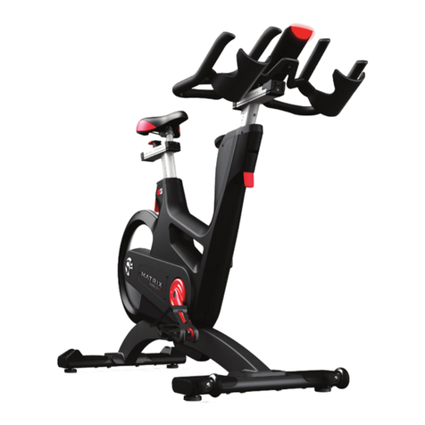
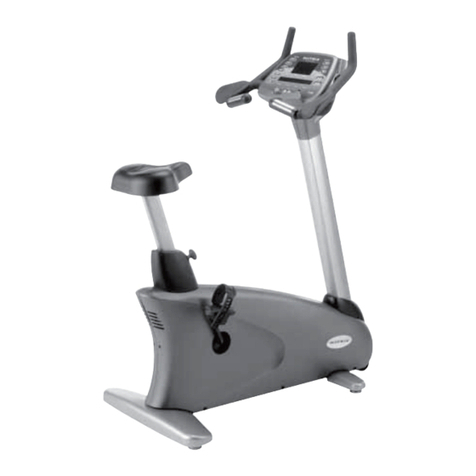
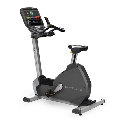
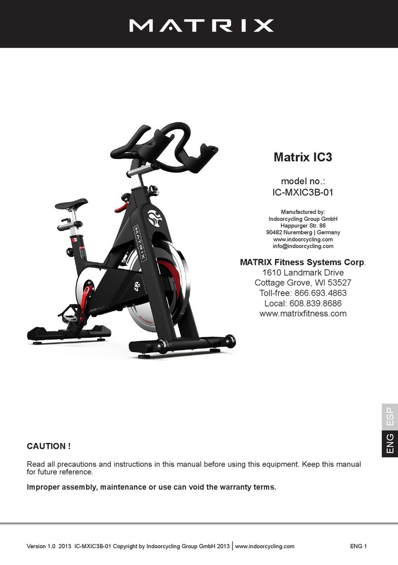
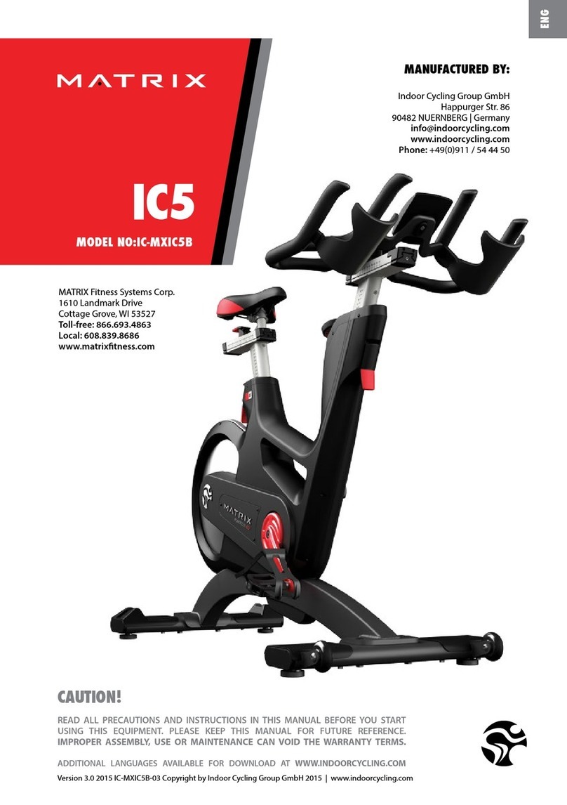
Matrix A7XI-01 User manual

A7XI-01 ASCENT TRAINER
SERVICE MANUAL

CHAPTER 1: SERIAL NUMBER LOCATION ........................................................... 1
CHAPTER 2: IMPORTANT SAFETY INSTRUCTIONS
2.1 Read and Save These Instructions............................................................................. 3
2.2 Electrical Requirements ............................................................................................. 4
CHAPTER 3: PREVENTATIVE MAINTENANCE
3.1 Recommended Cleaning Tips .................................................................................... 5
3.2 Check for Damaged Parts ......................................................................................... 5
3.3 Care and Maintenance Instructions ........................................................................... 6
3.4 Touch Screen Care & Cleaning .................................................................................. 7
3.5 Auto Calibration Instructions ....................................................................................... 7
CHAPTER 4: CONSOLE OVERLAY AND WORKOUT DESCRIPTION
4.1 Console Description ................................................................................................... 8
4.2 Workout Setup Steps ................................................................................................. 9
CHAPTER 5: MANAGER MODE
5.1 Using Manager Mode ................................................................................................ 10
5.2 Manager Mode - General........................................................................................... 11
5.3 Manager Mode - Workout .......................................................................................... 14
5.4 Manager Mode - Setup Defaults................................................................................ 16
5.5 Manager Mode - Asset Management......................................................................... 18
5.6 Manager Mode - Weather .......................................................................................... 18
5.7 Manager Mode - TV ................................................................................................... 19
5.8 Manager Mode - Applications .................................................................................... 20
5.9 Manager Mode - Hardware ........................................................................................ 21
5.10 Manager Mode - Service............................................................................................ 22
CHAPTER 6: ENGINEERING MODE
6.1 Using Engineering Mode ........................................................................................... 23
6.2 Engineering Mode - General...................................................................................... 24
6.3 Engineering Mode - Workout ..................................................................................... 27
6.4 Engineering Mode - Setup Defaults........................................................................... 29
6.5 Engineering Mode - Network ..................................................................................... 30
6.6 Engineering Mode - Asset Management.................................................................... 31
6.7 Engineering Mode - Weather ..................................................................................... 32
6.8 Engineering Mode - TV .............................................................................................. 32
6.9 Engineering Mode - Applications................................................................................ 34
6.10 Engineering Mode - Calibration.................................................................................. 34
6.11 Engineering Mode - Hardware.................................................................................... 35
6.12 Engineering Mode - Service ....................................................................................... 36
6.13 Engineering Mode - Errors ......................................................................................... 36
CHAPTER 7: SERVICE MODE
7.1 Using Service Mode. .................................................................................................. 37
7.2 Service Mode - General ............................................................................................. 38
7.3 Service Mode - Workout............................................................................................. 41
7.4 Service Mode - Setup Defaults .................................................................................. 43
7.5 Service Mode - Update .............................................................................................. 44
7.6 Service Mode - Network............................................................................................. 45
7.7 Service Mode - Asset Management ........................................................................... 46
7.8 Service Mode - Weather ............................................................................................ 46
7.9 Service Mode - TV...................................................................................................... 47
7.10 Service Mode - Applications ....................................................................................... 48
7.11 Service Mode - Calibration ......................................................................................... 49
7.12 Service Mode - Hardware........................................................................................... 50
7.13 Service Mode - Virtual Active ..................................................................................... 52
7.14 Service Mode - Management ..................................................................................... 52
7.15 Service Mode - Service .............................................................................................. 53
7.16 Service Mode - Errors ................................................................................................ 53
7.17 Service Mode - Netpulse ............................................................................................ 54
TABLE OF CONTENTS

III
7.18 Matrix fitness 7xi series feature access codes........................................................... 55
CHAPTER 8: TROUBLESHOOTING
8.1 Electrical Diagrams .................................................................................................... 56
8.2 LCB Error Indicators .................................................................................................. 60
8.3 LCB Wiring Connections............................................................................................. 61
8.4 Troubleshooting - Error 04A0...................................................................................... 62
8.5 Troubleshooting - Error 04B0...................................................................................... 63
8.6 Troubleshooting - Error 0140 / 014D .......................................................................... 64
8.7 Troubleshooting - Error 01A1...................................................................................... 65
8.8 Troubleshooting - Error 0147 ...................................................................................... 66
8.9 Troubleshooting - Error 0148 ...................................................................................... 67
8.10 Troubleshooting - Error 0149 ...................................................................................... 68
8.11 Troubleshooting - Error 01B4...................................................................................... 69
8.12 Troubleshooting - Error 02AB ..................................................................................... 70
8.13 Troubleshooting - Error 02B4...................................................................................... 71
8.14 Troubleshooting - Error 0248 ...................................................................................... 72
8.15 Troubleshooting - Error 014A / 0247........................................................................... 73
8.16 Troubleshooting - No resistance Issues...................................................................... 74
8.17 Troubleshooting - Heart Rate Issues .......................................................................... 75
8.18 TV Troubleshooting - Overview................................................................................... 76
8.19 TV Troubleshooting - Picture Fuzzy or Unclear.......................................................... 77
8.20 TV Troubleshooting - TV Will Not Turn On ................................................................. 78
8.21 TV Troubleshooting - Entertainment Keypad Issues .................................................. 79
CHAPTER 9: PART REPLACEMENT GUIDE
9.1 Front Disk Replacement ............................................................................................ 80
9.2 Front Shroud Replacement......................................................................................... 81
9.3 Lower Control Board (LCB) Replacement .................................................................. 84
9.4 Generator Replacement.............................................................................................. 85
9.5 Generator Belt Replacement ...................................................................................... 87
9.6 Drive Belt Replacement .............................................................................................. 88
9.7 Pulley Axle Set Replacement...................................................................................... 89
9.8 Drive Axle Set Replacement ....................................................................................... 90
9.9 Crank Replacement .................................................................................................... 94
9.10 Console Replacement................................................................................................. 95
9.11 Console Overlay and Keypad Replacement............................................................... 96
9.12 Console Mast Handlebar Replacement ...................................................................... 98
9.13 Incline Motor Replacement ......................................................................................... 99
9.14 Dual Action Handlebar Replacement .......................................................................... 102
9.15 Foot Pedals Replacement........................................................................................... 103
9.16 Pedal Arm Replacement ............................................................................................. 104
9.17 Link Arm Replacement................................................................................................ 105
9.18 Swing Arm Replacement............................................................................................. 106
9.19 Vertical Stabilizer Arm Replacement........................................................................... 107
9.20 Incline Arm Cover Replacement ................................................................................. 108
9.21 Handlebar Service....................................................................................................... 109
9.22 Testing the Ascent Trainer........................................................................................... 110
CHAPTER 10: EXPLODED DIAGRAMS
10.1 Ascent Trainer Specifications ..................................................................................... 111
10.2 Assembly Hardware .................................................................................................... 112
10.3 Ascent Trainer Assembly Steps ................................................................................. 113
10.4 Stabilizing the Ascent Trainer...................................................................................... 125
10.5 TV Programming Instructions ..................................................................................... 126
10.6 Using Update Manager............................................................................................... 132
10.7 Netpulse & AM Setting SOP ...................................................................................... 136
CHAPTER 11: SOFTWARE UPGRADE PROCEDURE
11.1 Software Upgrade Procedure ..................................................................................... 148
TABLE OF CONTENTS
1
1.1 SERIAL NUMBER LOCATION
CHAPTER 1: SERIAL NUMBER LOCATION
SERIAL NUMBER LOCATION

2
1.1 SERIAL NUMBER LOCATION - CONTINUED
CHAPTER 1: SERIAL NUMBER LOCATION
console serial number location
CONSOLE SERIAL NUMBER LOCATION

3
This Ascent Trainer is intended for commercial use. To ensure
your safety and protect the equipment, read all instructions before
operating the MATRIX Ascent Trainer.
When using an electrical product, basic precautions should always be
followed including the following:
CAUTION!
CAUTION!
2.1 READ AND SAVE THESE INSTRUCTIONS
CHAPTER 2: IMPORTANT SAFETY INSTRUCTIONS

4
CHAPTER 2: IMPORTANT SAFETY INSTRUCTIONS
2.2 ELECTRICAL REQUIREMENTS
110 V UNITS
All Matrix 3x, 5x, 7xe and 7xi require the use of a 100-125 V, 60 Hz and a 15 A “Dedicated
Circuit”, with a non-looped (isolated) neutral/ground for power. This outlet should be a NEMA
5-15R and have the same configuration as the plug. No adapter should be used with this
product. These Ascent Trainers can be daisy-chained together with up to 4 units per 15 A
dedicated circuit. Matrix daisy-chain cord adapters are sold separately.
220 V UNITS
All Matrix 3x, 5x, 7xe and 7xi 220 V Ascent Trainers require the use of a 216-250 V, 50 Hz and
a 15 A “Dedicated Circuit”, with a non-looped (isolated) neutral/ground for power. This outlet
should be a NEMA 6-15R and have the same configuration as the plug. No adapter should be
used with this product. These s can be daisy-chained together with up to 4 units per 15 A dedi-
cated circuit. Matrix daisy-chain cord adapters are sold separately.
NOTE: ALL UNITS WITH VIRTUAL ACTIVE™ MUST BE POWERED!
DEDICATED CIRCUIT AND ELECTRICAL INFO
A “Dedicated Circuit” means that each outlet you plug into should not have anything else running on that same circuit. The easiest way to verify
this is to locate the main circuit breaker box, and turn off the breaker(s) one at a time. Once a breaker has been turned off, the only thing that
should not have power to it are the units in question. No lamps, vending machines, fans, sound systems, or any other item should lose power
when you perform this test.
Non-looped (isolated) neutral/grounding means that each circuit must have an individual neutral/ground connection coming from it, and
terminating at an approved earth ground. You cannot “jumper” a single neutral/ground from one circuit to the next.
ELECTRICAL REQUIREMENTS
For your safety and to ensure good unit performance, the ground on this circuit must be non-looped (isolated). Please refer to NEC article 210-
21 and 210-23. Any alterations to the standard power cord provided could void all warranties of this product.
The A3x, E3x, A5x, E5x, A7xe and E7xe are designed to be self-powered and do not require an external power supply source to operate.
Without an external power supply, the console’s start-up time may be delayed. Add-on TV’s and other console accessories will increase the
time needed for start-up. An external power supply will ensure power is provided to the console at all times and is recommended when add-on
accessories are used.
For units with an integrated TV (like the 7xe and 7xi), the TV power requirements are included in the unit. An RG6 coaxial cable with ‘F Type’
compression fittings on each end will need to be connected to the cardio unit and the video source. Additional power requirements are not
needed for the add-on digital TV (3x and 5x). For units with an add-on PCTV (3x and 5x), the TV power requirements are separate.
GROUNDING INSTRUCTIONS
The unit must be grounded. If it should malfunction or breakdown, grounding provides a path of least resistance for electric current to reduce
the risk of electric shock. The unit is equipped with a cord having an equipment-grounding conductor and a grounding plug. The plug must be
plugged into an appropriate outlet that is properly installed and grounded in accordance with all local codes and ordinances. If the user does
not follow these grounding instructions, the user could void the Matrix limited warranty.
ADDITIONAL ELECTRICAL INFO
In addition to the dedicated circuit requirement, the proper gauge wire must be used from the circuit breaker box, to each outlet that will have
the maximum number of units running off of it. If the distance from the circuit breaker box to each outlet, is 100 ft (30.5 m) or less, then 12
gauge wire should be used. For distances greater than 100 ft (30.5 m) from the circuit breaker box to the outlet, a 10 gauge wire should be
used.
ENERGY SAVING / LOW-POWER MODE
All units are configured with the ability to enter into an energy saving / low-power mode when the unit has not been in use for a specified period
of time. Additional time may be required to fully reactivate this unit once it has entered the low-power mode. This energy saving feature may be
enabled or disabled from within the ‘Manager Mode’ or ‘Engineering Mode.
North American power cord plugs shown.
Depending on your country, the plug type may vary.

5
CHAPTER 3: PREVENTATIVE MAINTENANCE
3.1 RECOMMENDED CLEANING TIPS
In order to maximize life span, and minimize down time, all Matrix Fitness Equipment requires regularly
scheduled cleaning.
YOU WILL NEED:
- Mild dish soap and water mixture in a spray bottle (10:1 water to soap ratio).
- Lint free 100% cotton cleaning cloths or Micro fiber cleaning cloths.
- Vacuum / Shop Vac with extendable hose and soft brush attachment.
- LCD / LED or computer screen cleaner.
- Corrosion Block (available from Matrix - part # ZMS4001374).
DAILY:
1. Wipe down the unit after each use with a mild dish soap and water mixture. note: Spray the soap / water mixture onto the cloth.
NEVER spray directly onto the equipment. We recommend that you do NOT allow customers to use spray bottles to clean the equipment. If
the cleaner is sprayed directly on the equipment or over spray is present, it may cause your equipment to rust and / or cause damage to con-
sole overlays.
WEEKLY:
1. With a clean dry 100% lint free cloth and water / soap mixture, wipe down the entire frame so it is free of dust, dirt, and sweat.
2. With a clean dry 100% lint free cloth and water / soap mixture, wipe down the entire console area including the hand grips and hand rails.
3. Use a computer screen cleaner or LCD / LED screen cleaner on the touch screen portion of the console (see Section 3.4).
MONTHLY:
1. Vacuum under and around the Ascent Trainer. If you need to move it, unplug the unit first.
2. Vacuum debris out of the foot pedals. Remove the rubber foot pad and clean under it (Figure A).
3. Apply Corrosion Block to the metal part of the iPod cable.
DO NOT use any equipment that is damaged or has worn or broken parts. Use only replacement parts supplied by Matrix Fitness Systems.
MAINTAIN LABELS AND NAMEPLATES. Do not remove labels for any reason. They contain important information. If unreadable or missing,
contact Matrix Fitness Systems for a replacement. 1-866-693-4863, www.matrixfitness.com
MAINTAIN ALL EQUIPMENT Preventative maintenance is the key to smooth operating equipment. Equipment needs to be inspected at regular
intervals. Defective components must be replaced immediately. Improperly working equipment must be kept out of use until it is repaired.
Ensure that any person(s) making adjustments or performing maintenance or repair of any kind is qualified to do so. Matrix Fitness Systems will
provide service and maintenance training at our corporate facility upon request or in the field if proper arrangements are made.
3.2 CHECK FOR DAMAGED PARTS
FIGURE A

6
CHAPTER 3: PREVENTATIVE MAINTENANCE
3.3 CARE AND MAINTENANCE INSTRUCTION
In order to maximize life span, and minimize down time, all MATRIX equipment requires regular maintenance items performed on a scheduled
basis. This section contains detailed instructions on how to perform these items and the frequency of which they should be done. Some basic
tools and supplies will be necessary to perform these tasks which include (but may not be limited to):
* Metric Allen wrenches
* #2 Phillips head screwdriver
* Adjustable wrench
* Teflon based spray lubricant such as “Super Lube”, or other Matrix approved product
You may periodically see an addendum to this document, as the Matrix Technical Support Team identifies items that require specific attention, the
latest version will always be available on the Matrix website, www.matrixfitness.com
DAILY MAINTENANCE ITEMS
1. Attempt to wobble the unit back and forth, level if needed (see Section 10.4).
QUARTERLY MAINTENANCE ITEMS
1. Check all connecting joint areas for tightness of bolt assemblies.
2. Ensure that there is little, or no free play at all joint assemblies once bolts have been tightened. Installation of washer kits may be required
if free play does not come out from tightening bolts.
3. Remove plastic covers, and lubricate the ball joint where the Link Arm and Handlebar join together. Use your finger to apply grease to the
ball bearing. Matrix recommends using Superlube brand grease with PTFE {Teflon} additive.
4. Lubricate the Acme screw on the incline motor (Matrix recommends using Superlube brand grease with PTFE {Teflon} additive).
5. Check the pedal foot pad for damage or wear. Replace as needed.
YEARLY MAINTENANCE ITEMS
1. Remove the front round covers and check the belts for damage, alignment, and proper tension.

7
AUTO CALIBRATION INSTRUCTIONS
After initial installation or replacement of the incline motor, auto calibration should be run.
1) Press ENTER, 2, 0, 0, 1, ENTER on the keypad to go into Engineering Mode.
2) Press CALIBRATION key on the display.
3) Press CALIBRATION on the display.
4) This will run the Auto Calibration. If the calibration passes, it will say complete. Press the HOME key to return to the normal start screen.
5) If the calibration does not pass, contact Matrix Customer Technical Support at 866-693-4863 ext 3.
3.5 AUTO CALIBRATION INSTRUCTIONS
3.4 TOUCH SCREEN CARE & CLEANING
CHAPTER 3: PREVENTATIVE MAINTENANCE
TOUCH SCREEN CARE AND CLEANING
* The touch screen requires very little maintenance. We recommend that you periodically clean the touch screen surface with a clean dry 100%
lint free cloth and water / soap mixture or a computer or LCD / LED screen cleaner.
* It is very important to avoid using any other chemical on the touch screen.
* Always dampen the cloth and clean the screen. Do not spray the water / soap mixture on the screen itself, the drips can seep into the display
or stain the bezel.
* After cleaning, make sure the surface is dry. There should not be any left over solvent to seep into the display.
* It is very important to handle the touch screen with care. Do not use excessive force when cleaning.
* Do not use any sharp materials to clean the touch screen surfaces.
* Do not use high pressure air, water, or steam to clean the touch screen surface.

8
4.1 CONSOLE DESCRIPTION
CHAPTER 4: CONSOLE OVERLAY AND WORKOUT DESCRIPTION
The A7xi has a fully integrated touch screen display. All information required for workouts is explained on screen. Exploration of the interface is
highly encouraged. The information explaining how to program for various workouts will give an explanation about the contents of each screen.
Go: One touch Start.
stoP: Ends workout and shows workout summary data.
cool DoWn (displayed on-screen during workout): Puts unit into Cool Down mode. Cool Down time is dependent on the length of the workout.
Workouts 19 minutes and shorter will have a cool down length of 2 minutes. Workouts 20 minutes and longer will have a cool down length of 5
minutes.
A7XI ENTERTAINMENT ZONE
Will take the user directly to the iPod screen to allow for iPod control and playlist selection.
Volume uP / DoWn: Adjusts the volume output through the headphone jack of the integrated console TV or iPod output.
Allows for easy TV channel selections.
cHannel uP / DoWn: Allows for channel selection.
Allows user to cycle through console display options, iPod, TV, or profile display.
last cHannel: Allows the user to cycle between the current channel and the previous channel viewed.
cc/mute: Mutes sound and turns closed captioning on or off.

9
To set up a workout, press the touch screen over the program you
would like to use and then follow the prompts to begin your workout.
Go - Press to immediately begin a workout. Workout, resistance
level, and time will automatically go to default settings. Pressing GO
will not prompt user for age, weight, or level settings.
manual - Manual allows the user to input more information while
defining their own workout. Calorie expenditure will be more accurate
when inputting information in Manual than by pressing GO.
Fat burn - Fat burn is a level based program that is designed to
help users burn fat through various resistance level changes.
rollinG Hills - The Rolling Hills program is a level based
program that automatically adjusts the resistance level to simulate real
terrain.
interVals - The Intervals program is a level based program that
automatically adjusts the resistance of the machine from low to high
intensity settings at regular intervals.
- This program was designed
to increase your range of motion and target the thighs and glutes.
By varying a high incline throughout the workout you can engage
significant glute recruitment and enjoy a great workout. You will
be asked to enter in a minimum resistance level and a maximum
resistance level. The maximum resistance is applied at your peaks
and the minimum resistance is applied in the valleys. Choose levels
that are appropriate for you. A great recommended starting point is a
Minimum Resistance Level of 1 and a Maximum Resistance Level of
8. After you are comfortable with this setting, try higher levels for both.
Incline levels cannot be adjusted during this workout as it is an incline
based workout.
tarGet Heart rate - The Matrix Ascent Trainer comes
with standard digital contact heart rate sensors and are POLAR
telemetry compatible. The heart rate control workout mode allows
the user to program their desired heart rate zone, and the Ascent
Trainer will automatically adjust the level based upon the user's heart
rate. The heart rate zone is calculated using the following equation:
(220-Age)8%=target heart rate zone. The user must wear a POLAR
telemetric strap or continually hold onto the contact heart rate grips for
this workout.
Locate the metal sensors on the handlebars of the Ascent Trainer.
Notice that there are two separate pieces of metal on each grip.
You must be making contact with both pieces of each grip to get
an accurate heart rate reading. You can grab these sensors in any
program to view your current heart rate.
Fitness test -The Cooper Fitness Test measures cardiovascular
fitness and proves an estimated sub-maximal VO2 result. It is based on
power output according to ACSM standards and was developed by the
Cooper Institute© (www.cooperinstitute.org). User RPMs must remain
between 60-80 RPM during the test. The test will end when the user can
no longer maintain this speed. Use of a heart rate strap is optional but
provides more data.
The test starts at a low intensity level and gradually increases in intensity
(difficulty) every 2 minutes. As it increases, the user must maintain 60-80
RPM to advance to the next level. The test could take upwards of 30+
minutes for very fit individuals. Once the test ends a recovery period
(cool down) will begin and the user's results are calculated and displayed.
Results are based on the number of stages completed. Incline will not be
adjustable during the test.
STAGE COMPLETE:
1 Well Below Average
2 Well Below Average
3 Below Average
4 Below Average
5 Average
6 Average
7 Above Average
8 Above Average
9+ Well Above Average
constant Watts - Constant Watts is a unique program that
allows you to vary your cadence or RPM and the Ascent Trainer's
resistance level will adjust accordingly to your selected goal. The quicker
you pedal, the less resistance for the goal selected.
4.2 WORKOUT SETUP STEPS
CHAPTER 4: CONSOLE OVERLAY AND WORKOUT DESCRIPTION

10
CHAPTER 5: MANAGER MODE
1) To enter Manager Mode, press "ENTER, 1, 0, 0, 1, ENTER" on the number keypad and Manager Mode will appear on the display.
2) Manager Mode is divided into 9 tabs, located on the left side of the screen. They are General, Workout, Setup Defaults, Asset Management,
Weather, TV, Applications, Hardware and Service.
3) Choose a tab by touching the screen over the desired tab.
4) Each of the tabs has options that will appear once you have chosen that particular tab.
5) Press the "HOME" button or the EMERGENCY STOP to exit Manager Mode.
5.1 USING MANAGER MODE

11
CHAPTER 5: MANAGER MODE
FUNCTION & DEFAULTS DESCRIPTIONS MODIFIED
Accumulated Time Total time on the unit since production. Cannot be modified.
Accumulated Distance Total distance on the unit since production. Cannot be modified.
Serial Number - Console This option displays the serial number of the console, not
editable (see Service Mode to change serial numbers).
Cannot be modified.
Serial Number - Frame This option displays the serial number of the platform, not
editable (see Service Mode to change serial numbers).
Cannot be modified.
MANAGER MODE
General
5.2 MANAGER MODE – GENERAL – TAB 1

12
CHAPTER 6: MANAGER MODE
FUNCTION & DEFAULTS DESCRIPTIONS MODIFIED
Date & Time This option sets the current date and time of the machine. N/A
MANAGER MODE
General
5.2 MANAGER MODE - GENERAL – TAB 2
FUNCTION & DEFAULTS DESCRIPTIONS MODIFIED
Screen Timeout This option sets the amount of time before the
console resets when paused or not in use.
Maximum: 120 sec
Maximum: 15 sec
Software Versions Software versions. Cannot be modified.
MANAGER MODE
General
5.2 MANAGER MODE - GENERAL – TAB 3

13
CHAPTER 5: MANAGER MODE
FUNCTION & DEFAULTS DESCRIPTIONS MODIFIED
Language Setup Sets the language used on the console. English (US), English (UK),
German, French, Italian,
Spanish, Dutch, Portuguese,
Korean, Israeli, Swiss, Russian,
Finnish, Taiwanese, Chinese, or
Japanese.
MANAGER MODE
General
5.2 MANAGER MODE – GENERAL – TAB 4

14
5.3 MANAGER MODE - WORKOUT – TAB 1
CHAPTER 5: MANAGER MODE
FUNCTION & DEFAULTS DESCRIPTIONS MODIFIED
Maximum Workout Time This option allows the club to set the
maximum workout duration limits during
peak and non peak hours.
Maximum: 120 Minutes
Minimum: 10 Minutes
Maximum Workout Calories This option allows the club to set the
maximum amount of workout calorie goals
during peak and non peak hours.
Maximum: 10000
Minimum: 50
Maximum Workout Distance This option allows the club to set the
maximum workout distance during peak
and non peak hours.
Maximum: 31.1 mi
Minimum: 0.1 mi
Pause Time This option controls the default pause time. Maximum: 10 Minutes
Minimum: 1 Minutes
Maximum Incline Starting incline level at each program start. Maximum: 100
Minimum: 0
Elevation This option controls the minimum elevation
parameter.
Maximum: 10000
Minimum: 0
MANAGER MODE
Workout

15
5.3 MANAGER MODE - WORKOUT – TAB 2
CHAPTER 5: MANAGER MODE
MANAGER MODE
Workout
FUNCTION & DEFAULTS DESCRIPTIONS MODIFIED
Min Cooldown Time This option allows the club to set the
minimum cool down duration limits during
peak and non peak hours.
Maximum: 5 Minutes
Minimum: 1 Minutes
Max Cooldown Time This option allows the club to set the
maximum cool down duration limits during
peak and non peak hours.
Maximum: 10 Minutes
Minimum: 5 Minutes
Max Cooldown Adjustment Time This option allows the club to set the
maximum cool down adjustment time
duration limits during peak and non peak
hours.
Maximum: 20 Minutes
Minimum: 5 Minutes

16
5.4 MANAGER MODE - SETUP DEFAULTS – TAB 1
CHAPTER 5: MANAGER MODE
FUNCTION & DEFAULTS DESCRIPTIONS MODIFIED
Level This option controls the default program
levels.
Maximum: 20
Minimum: 1
Age This option controls the default user's age
used in the target heart rate calculations.
Maximum: 99
Minimum: 10
Weight This option controls the default weight
used in the calorie calculations. Displayed
in native units (pounds or kilograms).
79~401 lbs
Gender This option sets the user's gender as
either male or female.
Male or Female
Default Workout Time This option controls the default program
time.
Maximum: 60
Minimum: 5
Default Workout Calories This option controls the default program
calories.
Maximum: 5000
Minimum: 50
MANAGER MODE
Setup Defaults

17
5.4 MANAGER MODE - SETUP DEFAULTS – TAB 2
FUNCTION & DEFAULTS DESCRIPTIONS MODIFIED
Default Workout Distance This option controls the default program
Distance.
Maximum: 12.4
Minimum: 0.1
Default Web Browser Page This option controls the default machine Web
Browser Page.
N/A
Show Sliders In Workout This option controls whether the Slider bars
show during a workout. True = On, False = Off.
True or False
Target Heart Rate Adjustment Type This option controls the Target Heart Rate
program adjustment type to Incline or Speed
Incline or Speed
MANAGER MODE
Setup Defaults
CHAPTER 5: MANAGER MODE
Table of contents
Other Matrix Exercise Bike manuals

Matrix
Matrix H7XE-05 User manual

Matrix
Matrix IC-MXIC3B-01 User manual

Matrix
Matrix U7xe-04 User manual

Matrix
Matrix U7XE-05 Bike User manual

Matrix
Matrix U5X-02 User manual

Matrix
Matrix H3XE-01 User manual

Matrix
Matrix U7xe User manual

Matrix
Matrix Livestrong 1 Series User manual

Matrix
Matrix IC-MXIC7B-02 User manual

Matrix
Matrix Performance Upright Cycle User manual

Matrix
Matrix R1x User manual

Matrix
Matrix H7X-03 User manual

Matrix
Matrix R7xe Installation instructions

Matrix
Matrix R7X-03 User manual

Matrix
Matrix R3x-01 User manual

Matrix
Matrix R30 User manual

Matrix
Matrix U7XE-03 User manual

Matrix
Matrix U7X-01 User manual

Matrix
Matrix U-1X-F User manual

Matrix
Matrix h5x-02 User manual