97114C (Rev. G - 07/01)
ERO28C*B ERO28RAC*B
PAGE 3
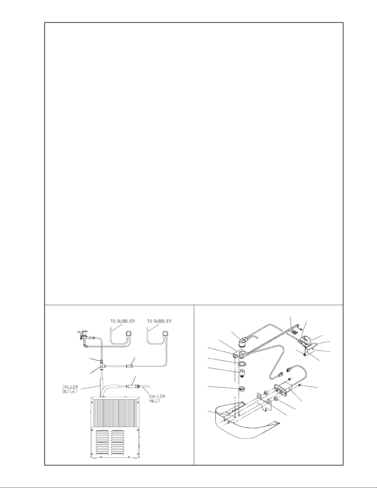
FIG. 4
INSTALLATION INSTRUCTIONS
16
39
FIG. 5
1. Install mounting frame. See mounting frame instructions.
2. Install remote chiller. Remove front panel of chiller. Slide chiller onto the shelf and position it to the left within the guides on the shelf.
3. Attach solenoid valve assy to the underside of cross member of mounting frame on electric eye unit. See Figure 9.
4. Make water supply connections. Install a shut-off valve and union connection to building water supply (valve and union not provided). Turn on the
water supply and flush the line thoroughly.
5. Make connection between remote chiller and building supply line. Remove the 3/8" x 1/4" union from the chiller inlet tube and install it on the water
inlet line of the upper fountain. Install the strainer on the chiller inlet tube. Install a 3/8" O.D unplated copper water line between the valve and the
cooler. Remove all burrs from the outside of the water line. Insert the 3/8" water line into the inlet side of the strainer by pushing it in until it reaches
a positive stop, approximately 3/4" (19mm). See Figures 2 and 4. DO NOT SOLDER TUBES INSERTED INTO THE STRAINER AS DAMAGE TO THE
O-RINGS MAY RESULT.
6. Make connection between remote chiller and solenoid valve assy. Install the 3/8" tee (provided) on the chiller outlet tube. Install the 3/8" stem x 1/4"
O.D. tube union (provided) into 3/8" tee (See Fig. 4). Install 1/4" O.D. formed tube (provided) between 3/8" stem x 1/4" O.D. tube union and the
straight fitting on solenoid valve assy.
7. Hang the upper panel on the mounting frame hanger. Align holes in the panel with holes in the mounting frame. Be sure that panel is engaged with
hanger at top of frame before releasing it.
8. Install fountains. Remove bottom cover plates on underside of fountains and save the screws. Mount the fountains to the upper panel and the wall
frame with (4) 5/16" x 3/4" (19mm) long bolts and nuts (provided). Tighten securely.
9. Connect solenoid valve assy and regulator holder in fountain with sensor by installing 1/4" O.D. x 24" straight tube (provided). Connect fountain with
push button to chiller by installing 3/8" O.D. x 30' tube (provided). Insert one end into remaining outlet of the 3/8" tee and the other end into the 3/8"
x 1/4" union that was removed from the chiller inlet and attached to the water inlet line on push button fountain.
10. Remove elbow from end of p-trap and attach it to drain tube. Re-attach elbow to p-trap and cut waste tube to required length using plumbing
hardware and trap as a guide.
11. Connect power cord of sensor to solenoid valve by running it through the back panel and connecting it as shown in Fig. 5. Connectors may be
connected to either terminal on solenoid valve. Attach ground wire to solenoid valve bracket with green ground screw.
12. Turn on water supply. Release air from tank by interrupting infrared beam; steady stream of water assures all air is removed. The sensor has a 30
second maximum ON time. It may be necessary to step away from beam a few times to allow chiller tank to refill. Check for leaks.
13. These products are designed to operate on 20-105 PSIG supply line pressure. If inlet pressure is above 105 PSIG, a pressure regulator must be
installed in the supply line. Any damage caused by reason of connecting these products to supply line pressures lower than 20 PSIG or higher than
105 PSIG is not covered by warranty.
14. Make electrical connections to chiller. See chiller instructions.
15. Check stream height from bubbler. Stream height is factory set at 35 PSI . If supply pressure varies greatly from this, remove items 28 and 36
and adjust the screw on the regulator (item 8). Clockwise adjustment will raise stream height and counter-clockwise will lower stream height. For best
adjustment stream height should hit basin approximately 6-1/2" (165mm) from the bubbler.
16. Mount lower panel. Loosen the (2) #10-24 x 5/8" (16mm) screws at frame bottom lip. Slide upper tongue of lower panel under lower edge of already
installed upper panel. Tighten previously loosened screws securely.
17. Replace bottom cover plate to fountain basin using screws provided. Tighten securely.
38
19
7
20
32
17
8
28
35
23
33
26
29
36
37
25 40
24
27
21