manuals.online logo
Brands
  1. Home
  2. •
  3. Brands
  4. •
  5. Elkron
  6. •
  7. Security Sensor
  8. •
  9. Elkron EL20 Series User manual

Elkron EL20 Series User manual

5EL20
APPLICATIONS
Windows
Terraces
External
protections
RX
TX
RX
TX
BARRIERE
PARALLELE
TX
RX
RX
TX
NO
SI
RX TX
TX
RX
RX
TX
RX
TX
BARRIERE
CONSECUTIVE
SI
NO
Figure 1
Internal
protections
Overall Characteristics
•4barrier models are available: EL20RT/05 (0,5m - 2 beams),
EL20RT/10 (1m - 4 beams), EL20RT/15 (1,5m - 6 beams), EL20RT/
20 (2m - 28beams).
•Extremely compact size allows installation between window and blinds,
or roller shade
•High resistance to shocks and to severe weather conditions, thanks to
the polycarbonate case and the gasket system on closing cover
•Resistance to UV rays
•Compensationofexpansioncausedbyheatexcursion,thankstoaspecial
expansionjoint.
•Maximum stability of columns installed on wall with intermediate fixtures
•Protection against accidental opening and removal
•Easy optical alignment (without calibration tools)
•Microprocessor-controlled SMD technology
•Three (3) selectable operating modes: point-to-point beams, adjacent
beams, crossed beams
•Selectablerange according to typeof installation (seeTXProgramming).
The distances shown are indicative and may change according to where
the barrier is installed.
•Identification code between TX and the corresponding RX
•Optical barrier synchronism (without connection in row)
•Alarm memory
Parallel
barriers Consecutive
barriers
NO
NO
YES
YES
Installation hints
•Avoid as much as possible the presence of objects that could obstruct
the beam
•Use of a shielded cable is advisable, preferably, one cable for each barrier
•If barriers are installed consecutively or in parallel, use the configuration
described in Figure 1
•Position the barriers so that the sun rays do not hit the receivers directly
(see figure 2).
• Check full operation of the barrier in the case of installation near large
reflecting surfaces which could cause undesired optical coupling.
•To fix columns, use only the screws supplied with the barrier
•The barrier can be installed either with the cable at top or at bottom; the
only precaution to be observed in this case is that
thetransmitter andthereceiverbothbe placedinthe
same direction (Figure 3)
•Tampering with the product will void the warranty.
•Thetwo columns are suppliedin pairs (Tx andRx).
Alwaysreplace the pair,ifrequiredformaintenance
purposes.
EL20 - Infrared outdoor barrier
TX
RX
RX
TX
Figure 2
NO YES
GB
Figure 3
YES
YES
NO
6EL20
Installation
•Arrange the columns (receiver and transmitter) one opposite the
other at the same height (the optical power of the Tx column can
be programmed according to the distance between the two columns
- see TX Programming). Mark the fixing screw holes and drill the
supporting surface; intermediate blocks (supplied on production
models more than half a meter high) are available to improve the
column’s adhesion to the wall: Read the NOTE below if you wish to
use these blocks, otherwise go to the next step.
•Fix the column to wall by inserting the fixing screws inside the
appropriate slotted holes, and tighten them (Figure 6).
•Insert the oval-shaped rubber seal (supplied on production models)
as shown in Figure 4.
•Run the cable through the appropriate slotted holes (Figure 6) if
you wish to use the rear core hitch.
•If necessary, cut the programming jumpers (see par. “TX and RX
Programming”).
•Cutthecolumn-stop posts (ontheRX andTX)beingcarefulto remove
anyresidual traces ofburrstoavoidcompromising theheatexpansion
compensation (Figure 6).
•Close the cover and fasten with appropriate screw (see Figure 5).
Slotted hole for
rear core hitch
superior
core hitch
Slotted hole for wall
fixing screw
Programming
jumpers
Anti-removal/anti-
opening microswitch
Column-stop posts
Fig.4 Fig.5
RX
foro per vite
di fissaggio
foro per vite
di fissaggio
foro per blocco
intermedio
foro per blocco
intermedio
Fig.8
Fig.6
Core hitch
Rubber
seal
NOTE 1: COLUMN WALL FIXING
•Afterhavingmarkedthe positionoffixing screwholes,
drill the holes necessary for the intermediate blocks
(Figure 8).
•Fix the intermediate blocks (with appropriate screws)
making sure that blocking fins can rotate freely (see
Figure 7).
•Fasten the column to the wall using the screws
supplied for this purpose.
•Push the fins of the intermediate blocks with a
screwdriver so that they rotate (Figure 9).
Fig.9
INTERMEDIATE
BLOCK FIN
fig.7
support
Hole for
fixing screw
Hole for
fixing screw
Hole for
intermediate block
Hole for
intermediate block
7EL20
INTEGRAL
JUMPERS
INTERRUPTION
TIME NEEDED TO
GENERATE AN
ALARM
No. OF
INTERRUPTED
BEAMS
No. OF
BARRIER BEAM
1 m
No. OF
BARRIER BEAM
1,5 m
1
2 ADJACENT
1 sec
>0.1 sec 246 8
YELLOW CUT
JUMPERS
1
2 ADJACENT
NO ALARM
>0.1 sec 246 8
2 CUT
JUMPERS 1
2
1 sec
>0.1 sec 410 16 22
1 sec. = allarme
0,2 sec. = allarme
1 sec. = allarme
NO
0,2 sec. = allarme
1 sec. = allarme
0,2 sec. = allarme
SUMMARY OF RX PROGRAMMING
TC Input
•The TC is a command generated by the anti-tampering unit to inform the barrier of the system’s condition (armed or disarmed).
When present (disarmed system), the TC enables:
- viewing of the alarm memory
- blocking of the alarm relay, for less wear.
•When it is not present (armed system), the TC command allows viewing of alarm events.
•The TC command is considered to be present when the writing –12 V is indicated on the corresponding cable (Brown).
•The TC command is considered to not be present when the writing 0 V is indicated on the corresponding cable (Brown), or when the
cable is not connected.
G
V
G
V
G
V
G = YELLOW JUMPER
V = GREEN JUMPER
TRANSMITTER
CONNECTION CABLES
•RED: POSITIVE
•BLACK: NEGATIVE
•BLUE: TAMPER
•WHITE: TAMPER
Factory Parameters
•The RX column is supplied with point
to-point operating mode.
•TheTX column is supplied with integral
jumper: minimum rating.
Fig.10
Fig.12
RX Programming
•Each RX column is supplied with 2 jumpers that are used for
programming the operating mode.
•INTEGRAL JUMPERS: POINT-TO-POINT BEAM MODE
An alarm is generated when a single beam is interrupted for at least
one second, or when 2 adjacent beams are interrupted for >0.1 sec.
•YELLOW CUT JUMPER: ADJACENT BEAM MODE
An alarm is generated when 2 adjacent beams are interrupted for at
least >0.1 sec.
•2 CUT JUMPERS: CROSSED BEAM MODE
An alarm is generated when a single beam is interrupted for at least
one second, or when 2 beams are interrupted for >0.1 sec.
WARNING: The range of crossed beams is typically 0.9 m and can
increase if the columns are installed in the presence of strong
environmental light.
TX Programming
• Each Tx column is supplied with 1 jumper for programming the
transmitted optical power as follows:
- integral jumper: reduced optical power
- cut jumper: maximum optical power
The following ranges are obtained according to the selected optical
power:
OUTDOOR INSTALLATION
•INTEGRAL JUMPER
MINIMUM RANGE 40 cm
MAX RANGE 2 m
•CUT JUMPER
MINIMUM RANGE 2 m
MAX RANGE 10 m
>0.1 sec = Alarm
1 sec = Alarm >0.1 sec = Alarm
>0.1 sec = Alarm
1 sec = Alarm
INDOOR INSTALLATION
•INTEGRAL JUMPER
MINIMUM RANGE 40 cm
MAX RANGE 5 m
•CUT JUMPER
MINIMUM RANGE 5 m
MAX RANGE 20 m
Connection
RECEIVER CONNECTION CABLES
•RED: POSITIVE
•BLACK: NEGATIVE
•GREEN: NC ALARM CONTACT
•YELLOW: NC ALARM CONTACT
•BROWN: TC INPUT
•BLUE: TAMPER
•WHITE: TAMPER
No. OF
BARRIER BEAM
0.5 m
No. OF
BARRIER BEAM
2 m
JUMPER
CONDITION
WARNING: - Detection faults or anomalies
may occur in the case of installation near
reflecting surfaces due to undesired optical
coupling. In many cases, the problem may
be solved by setting the curtain to reduced
optical power by leaving the Tx jumper intact.
Always check full functionality of the curtain
before completing installation
1 sec = NO Alarm Fig.11
8EL20
First powering up
•At first powering up, after the columns have been fixed one in front of the other, the beams are automatically synchronized by
the optical signal.
•The Coding of TX coupling with RX is performed automatically
•The receiver Led indicates any malfunctions:
- Led OFF: relay closed, barriers are functioning correctly
- Quick-flashing Led: see section titled “Troubleshooting”
Technical Characteristics
• RX-TX power supply nominal voltage ........................... 12 V—
• RX-TX power supply min-max ....................................... 10,5 - 15 V—
• Absorptions (typical-max) transmitter with 12 V— MIN RANGE MAX RANGE
EL20/05T........................................................................ 11 mA typ - 16 mA max 38 mA typ - 47 mA max
EL20/10T........................................................................ 13 mA typ - 20 mA max 64 mA typ - 73 mA max
EL20/15T........................................................................ 15 mA typ - 24 mA max 90 mA typ - 99 mA max
EL20/20T........................................................................ 17 mA typ - 28 mA max 116 mA typ - 127 mA max
• Absorptions (typical-max) receiver with 12 V— AT REST WITH ALARM
EL20/05R ....................................................................... 16 mA typ - 20 mA max 14 mA typ - 18 mA max
EL20/10R ....................................................................... 22 mA typ - 26 mA max 20 mA typ - 24 mA max
EL20/15R ....................................................................... 28 mA typ - 32 mA max 26 mA typ - 30 mA max
EL20/20R ....................................................................... 34 mA typ - 38 mA max 32 mA typ - 36 mA max
• Max range (adjustable on two levels) ............................ 10 m (Outdoor inst.) 20 m (Indoor inst.)
• Alarm times .................................................................... >0.1 sec (one ray interrupted)
1 sec (two adjacent rays interrupted)
• Emitters wave lenght...................................................... 940nm
• Issued signal .................................................................. PM transmission (pulse mode)
• Operating temperature certified (rules CEI) .................. -25°C - +55°C
• Alarm relay contact ........................................................ 0,1 A@24V— with serial protection R=10 Ohm
• Anti-tampering/anti-removal microswitch ..................... 50 mA@12 V—
• Degree of protection declared by builder....................... IP65 IK04
• Degree of protection certified (rules CEI)...................... IP34
• Fault indication ............................................................... Red LED flashing
• Size and weight
EL20/05 .......................................................................... 500 x 25 x 23 mm - weight 250 g
EL20/10 ..........................................................................1000 x 25 x 23 mm - weight 500 g
EL20/15 ..........................................................................1500 x 25 x 23 mm - weight 750 g
EL20/20.......................................................................... 2000 x 25 x 23 mm - weight 1000 g
Trouble
Led is lit with fixed light
and the relay contact is
open.
Led is flashing and the
relay contact is open
Led is always OFF and
the relay contact is open.
Led is lit with fixed light
and the relay contact is
closed
Led is always OFF and
the relay contact is closed.
Possible Cause
• Incomplete acquisition of random code
• Power supply to TX column missing
• Barrier is excessively off-center
• Range selection jumper is not set correctly
• RX column fault
• Power supply to RX column missing
• Alarm memory enabled
• TC present
Corrective Measure
•Check that there are no obstacles
between barriers
•Supply TX column
•Re-position barriers
•Check the distance between barriers and
select the correct range
•Check the RX column and replace, if
necessary
•Supply RX column
•Arm the system and disarm, if necessary
(refer to the TC input)
•Arm the system and check connections
Troubleshooting
ELKRON S.p.A.
Via Carducci, 3 - 10092 BEINASCO (TO) - ITALY
TEL. +39.011.3986711 - FAX +39.011.3499434

www.elkron.it e-mail [email protected]

Other manuals for EL20 Series

1

Other Elkron Security Sensor manuals

Elkron EIR500 User manual

Elkron

Elkron EIR500 User manual

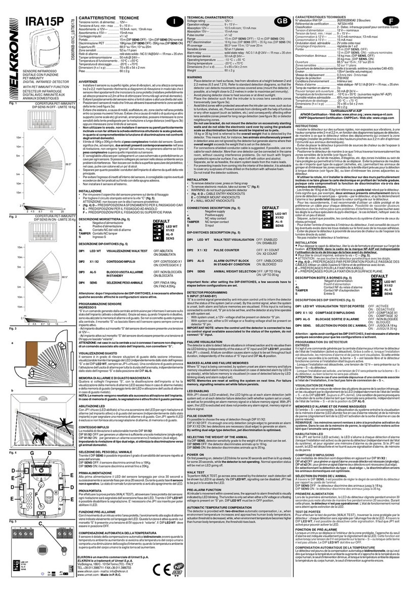
Elkron IRA15P User manual

Elkron

Elkron IRA15P User manual

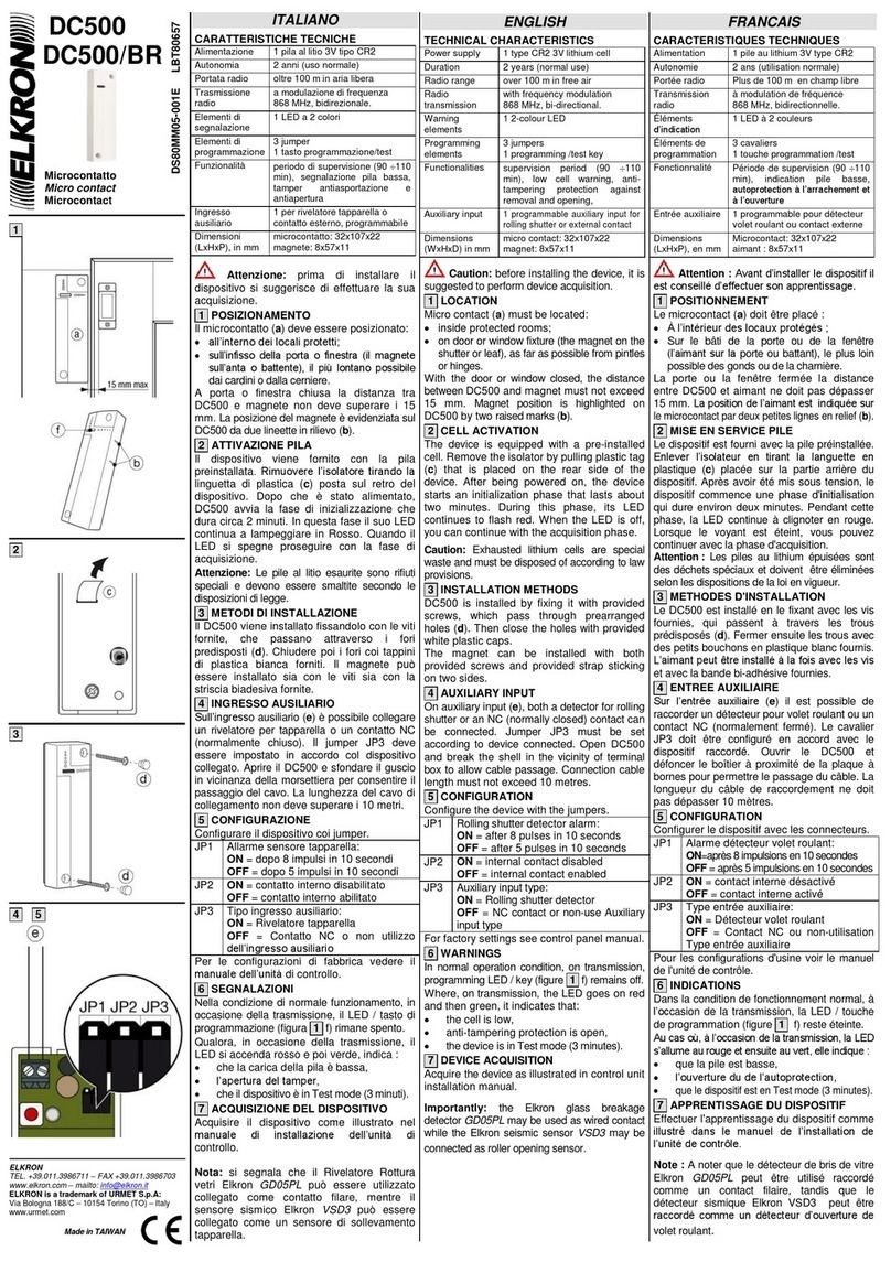
Elkron DC500 User manual

Elkron

Elkron DC500 User manual

Elkron PRO MEDEA KP710D User manual

Elkron

Elkron PRO MEDEA KP710D User manual

Elkron DC600S Assembly instructions

Elkron

Elkron DC600S Assembly instructions

Elkron IRA31WL User manual

Elkron

Elkron IRA31WL User manual

Elkron IR600VC User manual

Elkron

Elkron IR600VC User manual

Elkron DC200 User manual

Elkron

Elkron DC200 User manual

Elkron MP3040 User manual

Elkron

Elkron MP3040 User manual

Elkron MP3040 User manual

Elkron

Elkron MP3040 User manual

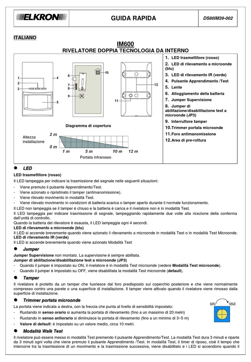
Elkron IM600 Assembly instructions

Elkron

Elkron IM600 Assembly instructions

Elkron IRA14 User manual

Elkron

Elkron IRA14 User manual

Elkron DC600S User manual

Elkron

Elkron DC600S User manual

Elkron FDT500 Guide

Elkron

Elkron FDT500 Guide

Elkron FAP54 User manual

Elkron

Elkron FAP54 User manual

Elkron EIR600 Assembly instructions

Elkron

Elkron EIR600 Assembly instructions

Elkron VSD3 User manual

Elkron

Elkron VSD3 User manual

Elkron IR600VC Assembly instructions

Elkron

Elkron IR600VC Assembly instructions

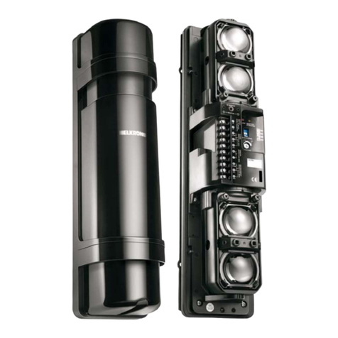
Elkron EL50RT 4PH 250m User manual

Elkron

Elkron EL50RT 4PH 250m User manual

Elkron EL60RT 2PH User guide

Elkron

Elkron EL60RT 2PH User guide

Elkron IR600FC/N Assembly instructions

Elkron

Elkron IR600FC/N Assembly instructions

Elkron ELKEIR600 Assembly instructions

Elkron

Elkron ELKEIR600 Assembly instructions

Elkron DT17 User guide

Elkron

Elkron DT17 User guide

Elkron IRT600 User manual

Elkron

Elkron IRT600 User manual

Popular Security Sensor manuals by other brands

VALCOBABY Vici TCD-3 instruction manual

VALCOBABY

VALCOBABY Vici TCD-3 instruction manual

C.P. Electronics MWS3A-AT-DD installation guide

C.P. Electronics

C.P. Electronics MWS3A-AT-DD installation guide

Aeotec MULTISENSOR 6 user guide

Aeotec

Aeotec MULTISENSOR 6 user guide

SGB VLXE Ex M Series Documentation

SGB

SGB VLXE Ex M Series Documentation

STEINEL IS 180 series operating instructions

STEINEL

STEINEL IS 180 series operating instructions

GEV RONDO FLAT 360 LBD 16811 manual

GEV

GEV RONDO FLAT 360 LBD 16811 manual

AJAX FireProtect 2 Heat/CO Jeweller manual

AJAX

AJAX FireProtect 2 Heat/CO Jeweller manual

D-tect Systems D-TECT GJD360/AM quick start guide

D-tect Systems

D-tect Systems D-TECT GJD360/AM quick start guide

BEA LZR- FLATSCAN REV-PZ user guide

BEA

BEA LZR- FLATSCAN REV-PZ user guide

Honeywell HAQSPA-R quick start guide

Honeywell

Honeywell HAQSPA-R quick start guide

Risco RK350DT installation instructions

Risco

Risco RK350DT installation instructions

CAME Security SIR215 quick start guide

CAME

CAME Security SIR215 quick start guide

System Sensor B501BI-IV Installation and maintenance instructions

System Sensor

System Sensor B501BI-IV Installation and maintenance instructions

Pepperl+Fuchs DoorScan Original operating instructions

Pepperl+Fuchs

Pepperl+Fuchs DoorScan Original operating instructions

Homematic IP HmIP-SMI55 Mounting instruction and operating manual

Homematic IP

Homematic IP HmIP-SMI55 Mounting instruction and operating manual

PCB Piezotronics 4104-01A Installation and operating manual

PCB Piezotronics

PCB Piezotronics 4104-01A Installation and operating manual

SICK Prime KTX-WN91241242ZZZZ manual

SICK

SICK Prime KTX-WN91241242ZZZZ manual

Schulz hidro lav 2950W instruction manual

Schulz

Schulz hidro lav 2950W instruction manual

manuals.online logo
manuals.online logoBrands
  • About & Mission
  • Contact us
  • Privacy Policy
  • Terms and Conditions

Copyright 2025 Manuals.Online. All Rights Reserved.