manuals.online logo
Brands
  1. Home
  2. •
  3. Brands
  4. •
  5. Elmo
  6. •
  7. Servo Drive
  8. •
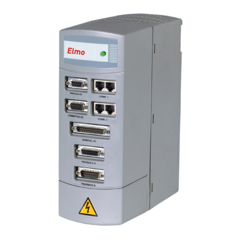
  9. Elmo Gold Series User manual

Elmo Gold Series User manual

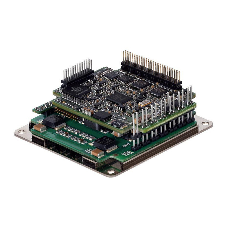
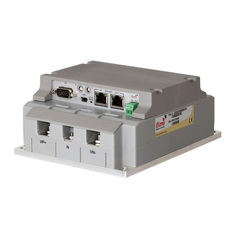
Gold Line Panel Mounted
Servo Drive Hardware
Manual
December 2019 (Ver. 1.020) www.elmomc.com
Notices
General Notice
This guide is delivered subject to the following conditions and restrictions:
•This guide contains proprietary information belonging to Elmo Motion Control Ltd. Such
information is supplied solely for the purpose of assisting users of the Gold Panel Mounted
Servo Drive in its installation.
•The text and graphics included in this manual are for the purpose of illustration and
reference only. The specifications on which they are based are subject to change without
notice.
•Information in this document is subject to change without notice.
•The Gold Digital Servo Drive has been developed, produced, tested and documented in
accordance with the relevant standards. Elmo Motion Control is not responsible for any
deviation from the configuration and installation described in this documentation.
Furthermore, Elmo is not responsible for the performance of new measurements or
ensuring that regulatory requirements are met.
This documentation was written in English.
Elmo Motion Control and the Elmo Motion Control logo are registered
trademarks of Elmo Motion Control Ltd.
EtherCAT Conformance Tested. EtherCAT®is a registered trademark and
patented technology, licensed by Beckhoff Automation GmbH, Germany.
CANopen compliant. CANopen®is a registered trademark and patented
technology, licensed by CAN in Automation (CiA) GmbH, Kontumazgarten 3,
DE-90429 Nuremberg, Germany.
Safety related programmable electronic system compliant as per Certificate
Z10 13 08 84596 001. TUV®is a registered trademark licensed by TÜV SÜD
Product Service GmbH, Ridlerstraße 57, D-80339 München, Germany
UL Recognized. UL®is a registered trademark licensed by Underwriters
Laboratories, 333 Pfingsten Road, Northbrook, IL 60062-2096, U.S.A.
UL Recognized. CUL®is a registered trademark licensed by Canadian
Underwriters Laboratories, 7 Underwriters Road, Toronto, ON M1R 3A9
Document no. MAN-G-PMDRIVEHM-EC (Ver. 1.020)
Copyright 2019
Elmo Motion Control Ltd.
All rights reserved.
Table of Contents
MAN-G-PMDRIVEHM-EC (Ver. 1.020)4
Chapter 1: Introduction................................................................................................8
1.1. Gold Servo Drives Power............................................................................................9
1.1.1. DC Products .................................................................................................9
1.1.2. AC Products ...............................................................................................21
1.1.3. ExtrIQ Products..........................................................................................24
1.2. Elmo Part Number Description ................................................................................30
Chapter 2: Safety Information ....................................................................................33
2.1. Safety Referenced in this Document........................................................................33
2.2. Warnings ..................................................................................................................34
2.3. Cautions....................................................................................................................34
2.4. CE Marking Conformance.........................................................................................34
2.5. Warranty Information ..............................................................................................34
Chapter 3: Product Features .......................................................................................35
3.1. System Architecture .................................................................................................35
3.2. Servo Control............................................................................................................37
3.3. Advanced Filters and Gain Scheduling .....................................................................37
3.4. Motion Control.........................................................................................................38
3.5. Fully Programmable .................................................................................................38
3.6. Feedback Ports Options ...........................................................................................38
3.7. Feedback Sensor Specifications ...............................................................................39
3.8. Communications.......................................................................................................40
3.9. Safe Torque Off (STO)...............................................................................................40
3.10. Digital Outputs..........................................................................................................40
3.11. Differential Outputs .................................................................................................41
3.12. Digital Inputs ............................................................................................................41
3.13. Differential Inputs ....................................................................................................41
3.14. Analog Input .............................................................................................................41
3.15. Built-In Protection ....................................................................................................41
3.16. Status Indication.......................................................................................................42
3.17. Automatic Procedures..............................................................................................42
Chapter 4: Installation................................................................................................43
4.1. How to Use this Guide..............................................................................................43
4.2. Unpacking the Drive Components ...........................................................................44
Chapter 5: Wiring.......................................................................................................45
5.1. Wiring Legend...........................................................................................................45
Chapter 6: Common and Returns................................................................................47
Chapter 7: Drive Status Indicator ................................................................................47
Chapter 8: Motor Power.............................................................................................48
Table of Contents
MAN-G-PMDRIVEHM-EC (Ver. 1.020)5
Chapter 9: STO (Safe Torque Off)................................................................................51
9.1. Motor Type for STO..................................................................................................51
9.2. STO Signals ...............................................................................................................51
9.3. STO Functional Description ......................................................................................52
9.4. Safety Controller Short Pulses for Diagnostics.........................................................52
9.5. STO input Interface...................................................................................................53
9.5.1. Source Mode – PLC Voltage Level .............................................................53
9.5.2. TTL Mode – TTL Voltage Level ...................................................................54
9.5.3. STO Connection of Several Drives .............................................................55
9.6. STO Output Status (upon customer request)...........................................................56
9.7. Diagnostics ...............................................................................................................58
9.7.1. STO Status Register....................................................................................58
9.7.2. ELMO Status Register ................................................................................59
9.7.3. Drive Status Indicator ................................................................................59
9.7.4. STO Output Status – GO[1 to 4] ................................................................59
9.8. STO Start-Up.............................................................................................................60
9.9. Maintenance ............................................................................................................61
9.10. STO Timing................................................................................................................61
9.11. STO Standards Data..................................................................................................64
Chapter 10: Feedbacks .................................................................................................65
10.1. Introduction..............................................................................................................65
10.2. Feedback Supply Voltage .........................................................................................65
10.3. Feedback Port A .......................................................................................................66
10.3.1. Incremental Encoder .................................................................................67
10.3.2. Hall Sensors ...............................................................................................69
10.3.3. Absolute Serial Encoder.............................................................................71
10.3.3.1. EnDat 2.2 ..................................................................................74
10.3.3.2. BISS-C and B..............................................................................74
10.3.3.3. Panasonic..................................................................................75
10.3.3.4. Tamagawa.................................................................................75
10.3.3.5. Sanyo / Nikon ...........................................................................76
10.3.3.6. SSI .............................................................................................76
10.3.3.7. Hiperface ..................................................................................77
10.4. Feedback Port B........................................................................................................79
10.4.1. Incremental Encoder .................................................................................80
10.4.2. Interpolated Analog (Sine/Cosine) Encoder..............................................82
10.4.3. Resolver .....................................................................................................84
10.5. Port C –Encoder Output ...........................................................................................86
10.5.1. Introduction...............................................................................................86
10.5.2. Signals........................................................................................................86
10.5.3. Specification ..............................................................................................87
10.5.4. Connections...............................................................................................88
10.6. Gantry.......................................................................................................................89
Table of Contents
MAN-G-PMDRIVEHM-EC (Ver. 1.020)6
10.6.1. Connection from Port C to Port A..............................................................90
10.6.2. Connection from Port C to Port B..............................................................91
10.6.3. Selecting the Appropriate Cable Configuration.........................................92
10.6.3.1. Connection from Port C to Port A.............................................92
10.6.3.2. Connection from Port C to Port B.............................................92
Chapter 11: User I/Os...................................................................................................93
11.1. Digital I/Os................................................................................................................93
11.1.1. Introduction...............................................................................................93
11.1.1.1. Source mode – TTL voltage level..............................................93
11.1.1.2. Source mode – PLC voltage level..............................................94
11.1.1.3. Sink mode – PLC voltage level ..................................................94
11.1.2. Digital Input and Output Signals................................................................95
11.1.2.1. TTL Digital Input........................................................................96
11.1.2.2. TTL Digital Output.....................................................................98
11.1.2.3. Source PLC Voltage Level Digital Input...................................100
11.1.2.4. Source PLC Voltage Level Digital Output................................102
11.1.2.5. Sink PLC Voltage Level Digital Input .......................................104
11.1.2.6. Sink PLC Voltage Level Digital Output ....................................106
11.2. Analog Input ...........................................................................................................108
11.3. Network I/O............................................................................................................109
Chapter 12: Communications .....................................................................................110
12.1. USB 2.0 ...................................................................................................................110
12.2. EtherCAT/Ethernet.................................................................................................112
12.2.1. Introduction.............................................................................................112
12.2.2. Specification ............................................................................................112
12.2.3. EtherCAT with RJ-45 Connectors.............................................................112
12.2.3.1. Signals.....................................................................................112
12.2.3.2. EtherCAT Link Indicators.........................................................113
12.2.4. EtherCAT with D-TYPE Connectors..........................................................114
12.2.5. EtherCAT Status Indicator .......................................................................115
12.2.6. EtherCAT Switches...................................................................................115
12.2.7. EtherCAT Connectivity.............................................................................116
12.3. CAN.........................................................................................................................117
12.3.1. CAN Signals with RJ-45 Connectors.........................................................117
12.3.2. CAN with D-TYPE Connectors ..................................................................119
12.4. RS-232.....................................................................................................................119
12.5. RS-422 (Differential RS-232)...................................................................................121
Chapter 13: Environmental Conditions .......................................................................123
13.1. Gold Line.................................................................................................................123
13.2. ExtrIQ Series ...........................................................................................................123
Chapter 14: Control Specifications..............................................................................125
Table of Contents
MAN-G-PMDRIVEHM-EC (Ver. 1.020)7
14.1. Current Loop...........................................................................................................125
14.2. Velocity Loop..........................................................................................................125
14.3. Position Loop..........................................................................................................126
Chapter 15: Gold Line Standards.................................................................................127
15.1. Functional Safety....................................................................................................127
15.2. Safety......................................................................................................................131
15.3. CE Declaration ........................................................................................................131
15.4. Environmental ........................................................................................................132
15.5. EMC ........................................................................................................................132
15.6. EtherCAT Conformance..........................................................................................133
15.7. Other Compliant Standards....................................................................................134
Gold Line Panel Mounted Hardware Manual
MAN-G-PMDRIVEHM-EC (Ver. 1.020)
|Gold Servo Drives Power|www.elmomc.com
8
Table of Contents
Chapter 1:
Introduction
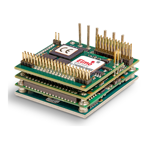
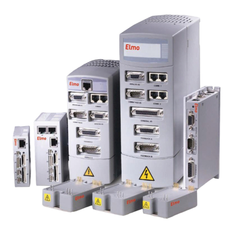
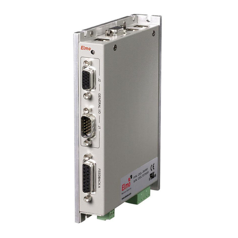
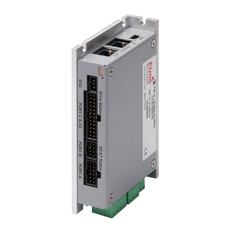
The Gold Panel Mounted Servo Drive is an advanced high power density servo drive. It provides top
servo performance, advanced networking and built-in safety, all in a compact package. The Gold line
has a fully featured motion controller and local intelligence.
The GOLD Line includes two main drives families dependent on the environmental operating
condition. While the GOLD servo drives are designed to meet ordinary environmental conditions, the
GOLD ExtrIQ servo drives are designed to meet Extreme environmental conditions.
The ExtrIQ models are a series of servo drives designed, verified, qualified, manufactured and tested
to endure extreme environmental conditions. The ExtrIQ line targets any application that has to
withstand any harsh conditions.
The Gold Panel Mounted Servo Drive can operate as a stand-alone device or as part of a multi-axis
system in a distributed configuration on a real-time network, and is easily set up and tuned using the
Elmo Application Studio (EASII) software tools.
As part of the Gold product line, it is fully programmable with the Elmo motion control language. For
more about software tools, refer to the Elmo Application Studio Software Manual.
The Gold Panel Mounted Servo Drive is available in a variety of options. There are multiple power
rating options, different communications options, a variety of feedback selections and I/O
configuration possibilities. The configuration of the drive is determined by the Catalog Number.
This hardware guide describes the hardware features of the Gold Panel Mounted Servo Drive and the
steps for its wiring, installation, power-up, and STO, feedback, and IO communication signals. The
wiring diagrams shown are examples, and for specific details of a Gold Panel Mounted Servo Drive,
please refer to the specific servo drive hardware manual. Following these guidelines ensures optimal
performance of the drive and the system to which it is connected. While this manual details and
describes the generic features of the Elmo servo drives, certain drives have unique features which are
fully detailed in their individual manuals.
The Gold Panel Mounted Servo Drives which include the ExtrIQ models share the same signals; but are
presented in different types of connectors:
•D-Type
•Shrouded
•Micro Hi-Reliability
Refer to the specific Gold Panel Mounted Servo Drive Installation Guide for the main and auxiliary
power signal, pinout, D-Type, and Shrouded connector wiring details.
Other Drive Hardware Manuals Available include the MAN-G-Board Level Modules Hardware Manual.
This manual describes the Gold series of hardware drives for mounting on a PCB by soldering its pins
directly to the PCB.
Gold Line Panel Mounted Hardware Manual
MAN-G-PMDRIVEHM-EC (Ver. 1.020)
|Gold Servo Drives Power|www.elmomc.com
9
Table of Contents
1.1. Gold Servo Drives Power
1.1.1. DC Products
The following describes the range of Gold DC Panel Mounted servo drives which subscribe to the
standard Environmental Conditions (refer to section 13.1).
Gold Line Panel Mounted Hardware Manual
MAN-G-PMDRIVEHM-EC (Ver. 1.020)
|Gold Servo Drives Power|www.elmomc.com
10
Table of Contents
Gold Whistle family G-DCWHI
Connector Type Shrouded connector
Current/Voltage
(Amps/VDC
1/100 2.5/100 5/100 10/100 15/100 20/100 3/200 6/200 9/200
Continuous Output Current (A) ranges 1 to 20 A. The current is given in amplitude.
Note: In all drives, the peak current IP=2xIC, except for “R” drives
Continuous Output
Power(W)
80 200 400 800 1200 1600 480 960 1450
Note: For all non-“R” drives, the power peak is x2.
STO TTL or 2
PLC Source 2
Digital Input
Options
TTL, or 6
PLC Source, or 6
PLC Sink 6
Digital Output
options
TTL, or 4
PLC Source, or 4
PLC Sink, or 4
Analog Input Differential ±10V 1
Feedback Standard Port A, B, & C √
Communication
Options
USB √
EtherCAT (option) √
EtherCAT with Switches
(option)
CAN (option) √
EIA RS-232 (Standard) -
Gold Line Panel Mounted Hardware Manual
MAN-G-PMDRIVEHM-EC (Ver. 1.020)
|Gold Servo Drives Power|www.elmomc.com
11
Table of Contents
Gold Whistle family G-SOLWHI
Connector Type Shrouded connector
Current/Voltage
(Amps/VDC
1/100 2.5/100 5/100 10/100 15/100 20/100 3/200 6/200 9/200
Continuous Output Current (A) ranges 1 to 20 A. The current is given in amplitude.
Note: In all drives, the peak current IP=2xIC, except for “R” drives
Continuous Output
Power(W)
80 200 400 800 1200 1600 480 960 1450
Note: For all non-“R” drives, the power peak is x2.
STO TTL or 2
PLC Source 2
Digital Input
Options
TTL, or 6
PLC Source, or 6
PLC Sink -
Digital Output
options
TTL, or 2
PLC Source, or 2
PLC Sink, or -
Analog Input Differential ±10V 1
Feedback Standard Port A, B, & C √
Communication
Options
USB √
EtherCAT (option) √
EtherCAT with Switches
(option)
CAN (option) √
EIA RS-232 (Standard) √
Gold Line Panel Mounted Hardware Manual
MAN-G-PMDRIVEHM-EC (Ver. 1.020)
|Gold Servo Drives Power|www.elmomc.com
12
Table of Contents
Gold Duo G-DUO
Includes two Gold Whistles
Connector Type Shrouded connector
Current/Voltage
(Amps/VDC
5/100 10/100 15/100 20/100 3/200 6/200 9/200
Continuous Output Current (A) ranges 5 to 20 A. The current is given in amplitude.
Note: In all drives, the peak current IP=2xIC, except for “R” drives
Continuous
Output Power(W)
400 800 1200 1600 480 960 1450
Note: For all non-“R” drives, the power peak is x2.
STO TTL, or 2
PLC Source 2
Digital Input
Options
TTL, or 6
PLC Source, or 6
PLC Sink -
Digital Output
Options
TTL, or 4
PLC Source, or 4
PLC Sink -
Analog Input Differential ±10V 1
Feedback Standard Port A, B, & C √
Communication
Options
USB √
EtherCAT (option) √
Gold Line Panel Mounted Hardware Manual
MAN-G-PMDRIVEHM-EC (Ver. 1.020)
|Gold Servo Drives Power|www.elmomc.com
13
Table of Contents
Gold Guitars, Cello G-SOLGUT
Connector Type Shrouded connector
Current/Voltage
(Amps/VDC
20/100 35/100 50/100 10/200 17/200 20/200
Continuous Output Current (A) ranges 10 to 50 A. The current is given in amplitude.
Note: In all drives, the peak current IP=2xIC, except for “R” drives
Continuous
Output
Power(W)
1600 2800 4000 1650 2800 3300
Note: For all non-“R” drives, the power peak is x2.
STO TTL, or 2
PLC Source 2
Digital Input
Options
TTL, or 6
PLC Source, or 6
PLC Sink 6
Digital Output
Options
TTL, or 4
PLC Source, or 4
PLC Sink 4
Analog Input Differential ±10V 1
Feedback Standard Port A, B, & C √
Communication
Options
USB √
EtherCAT (option) √
EtherCAT with Switches
(option)
√
CAN (option) √
EIA RS-232 (Standard) √
Gold Line Panel Mounted Hardware Manual
MAN-G-PMDRIVEHM-EC (Ver. 1.020)
|Gold Servo Drives Power|www.elmomc.com
14
Table of Contents
Gold Guitars, Cello G-CELLO
Connector Type D-Type
Current/Voltage
(Amps/VDC
20/100 35/100 50/100 10/200 17/200 20/200
Continuous Output Current (A) ranges 10 to 50 A. The current is given in amplitude.
Note: In all drives, the peak current IP=2xIC, except for “R” drives
Continuous
Output
Power(W)
1600 2800 4000 1650 2800 3300
Note: For all non-“R” drives, the power peak is x2.
STO TTL, or 2
PLC Source 2
Digital Input
Options
TTL, or 6
PLC Source, or 6
PLC Sink 6
Digital Output
Options
TTL, or 4
PLC Source, or 4
PLC Sink 4
Analog Input Differential ±10V 1
Feedback Standard Port A, B, & C √
Communication
Options
USB √
EtherCAT (option) √
EtherCAT with Switches
(option)
-
CAN (option) √
EIA RS-232 (Standard) -
Gold Line Panel Mounted Hardware Manual
MAN-G-PMDRIVEHM-EC (Ver. 1.020)
|Gold Servo Drives Power|www.elmomc.com
15
Table of Contents
Gold DC Bell G-DCBEL
Connector Type Shrouded connector
Current/Voltage
(Amps/VDC
1/100 2.5/100 5/100 10/100 15/100 3/200 6/200 9/200
Continuous Output Current (A) ranges 1 to 15 A. The current is given in amplitude.
Note: In all drives, the peak current IP=2xIC, except for “R” drives
Continuous
Output
Power(W)
80 200 400 800 1200 480 960 1450
Note: For all non-“R” drives, the power peak is x2.
STO TTL, or 2
PLC Source 2
Digital Input
Options
TTL, or 6
PLC Source, or 6
PLC Sink 6
Digital Output
Options
TTL, or 4
PLC Source, or 4
PLC Sink 4
Analog Input Differential ±10V 1
Single Ended -
Feedback Standard Port A, B, & C √
Communication
Options
USB √
EtherCAT (option) √
EtherCAT with Switches
(option)
-
CAN (option) √
Gold Line Panel Mounted Hardware Manual
MAN-G-PMDRIVEHM-EC (Ver. 1.020)
|Gold Servo Drives Power|www.elmomc.com
16
Table of Contents
Gold Trombone family G-DCTRO
Connector Type D-Type
Current/Voltage
(Amps/VDC
6/400 12/400 16/400 R17/400 R22/400 8/800 12/800 R11/800 R16/800
Continuous Output Current (A) ranges 6to 22 A. The current is given in amplitude.
Note: In all drives, the peak current IP=2xIC, except for “R” drives
Continuous Output
Power(W)
2000 4000 5000 5000 5500 5000 7500 7000 10,000
Continuous Output Power Note: For all non-“R” drives, the power peak is x2.
STO TTL, or 2
PLC Source 2
Digital Input Options TTL, or 6
PLC Source, or 6
PLC Sink 6
Digital Output
Options
TTL, or 4
PLC Source, or 4
PLC Sink 4
Analog Input Differential ±10V 1
Feedback Standard Port A, B, & C √
Communication
Options
USB √
EtherCAT (option) √
EtherCAT with
Switches (option)
-
CAN (option) √
EIA RS-232 (Standard) -
Gold Line Panel Mounted Hardware Manual
MAN-G-PMDRIVEHM-EC (Ver. 1.020)
|Gold Servo Drives Power|www.elmomc.com
17
Table of Contents
Gold Trombone family G-SOLTRO
Connector Type Shrouded connector
Current/Voltage
(Amps/VDC
6/400 12/400 16/400 R17/400 R22/400 8/800 12/800 R11/800 R16/800
Continuous Output Current (A) ranges 6to 22 A. The current is given in amplitude.
Note: In all drives, the peak current IP=2xIC, except for “R” drives
Continuous Output
Power(W)
2000 4000 5000 5000 5500 5000 7500 7000 10,000
STO TTL, or 2
PLC Source 2
Digital Input Options TTL, or 6
PLC Source, or 6
PLC Sink 6
Digital Output
Options
TTL, or 4
PLC Source, or 4
PLC Sink 4
Analog Input Differential ±10V 1
Feedback Standard Port A, B, & C √
Communication
Options
USB √
EtherCAT (option) √
EtherCAT with Switches
(option)
-
CAN (option) √
EIA RS-232 (Standard) -
Gold Line Panel Mounted Hardware Manual
MAN-G-PMDRIVEHM-EC (Ver. 1.020)
|Gold Servo Drives Power|www.elmomc.com
18
Table of Contents
Gold Drum family G-DRU
(D-Type)
Connector Type D-Type
Current/Voltage
(Amps/VDC
Operating Voltage Range 11 to 390 VDC
Continuous Output Current (A) ranges 18 to 100 A. The current is given in amplitude.
Note: In all drives, the peak current IP=2xIC, except for “R” drives
Continuous
Output
Power(W)
STO TTL, or 2
PLC Source 2
STO Output
Status (option)
Replacing
OUT4
Digital Input
Options
TTL, or 6
PLC Source, or 6
PLC Sink 6
Digital Output
Options
TTL, or 4
PLC Source, or 4
PLC Sink 4
Analog Input Differential ±10V 1
Feedback Standard Port A,
B, & C
√
Communication
Options
USB √
EtherCAT
(option)
√
EtherCAT with
Switches (option)
-
CAN (option) √
EIA RS-232
(Standard)
√
Differential RS-
232
√
Gold Line Panel Mounted Hardware Manual
MAN-G-PMDRIVEHM-EC (Ver. 1.020)
|Gold Servo Drives Power|www.elmomc.com
19
Table of Contents
Gold Drum family G-DRU
(RJ-45 Type)
Connector Type D-Type+RJ45
Power Operating Voltage Range
(VDC)
11 to 390
Continuous Output
Current (A)
The current is given in
amplitude.
Note: In all drives, the
peak current IP=2xIC,
except for “R” drives
18 to 100
Continuous Output
Power Range (kW)
Note: For all non-“R”
drives, the power peak is
x2.
2.70 to 9.60
STO TTL, or 2
PLC Source 2
STO Output Status
(option)
Replacing
OUT4, IN6
Digital Input
Options
TTL, or 6
PLC Source, or 6
PLC Sink 6
Digital Output
Options
TTL, or 4
PLC Source, or 4
PLC Sink 4
Analog Input Differential ±10V 1
Feedback Standard Port A, B, & C √
Communication
Options
USB √
EtherCAT (option) √
EtherCAT with Switches
(option)
-
CAN (option) √
EIA RS-232 (Standard) -
Differential RS-232 -
Gold Line Panel Mounted Hardware Manual
MAN-G-PMDRIVEHM-EC (Ver. 1.020)
|Gold Servo Drives Power|www.elmomc.com
20
Table of Contents
Gold Drum family G-DRUHV
Connector Type D-Type+RJ45
Power Operating Voltage
Range (VDC)
50 to 780
Continuous Output
Current (A)
The current is given
in amplitude.
Note: In all drives,
the peak current
IP=2xIC, except for
“R” drives
35 to 100
Continuous Output
Power Range (kW)
Note: For all non-“R”
drives, the power
peak is x2.
32.00 to
65.00
STO TTL, or 2
PLC Source 2
STO Output Status
(option)
Replacing
OUT4, IN6
Digital Input
Options
TTL, or 6
PLC Source, or 6
PLC Sink 6
Digital Output
Options
TTL, or 4
PLC Source, or 4
PLC Sink 4
Analog Input Differential ±10V 1
Feedback Standard Port A, B, &
C
√
Communication
Options
USB √
EtherCAT (option) √
EtherCAT with
Switches (option)
√
CAN (option) √
EIA RS-232
(Standard)
-
Differential RS-232 -

This manual suits for next models

17

Other Elmo Servo Drive manuals

Elmo SimplIQ Series User manual

Elmo

Elmo SimplIQ Series User manual

Elmo SimpliQ Line User manual

Elmo

Elmo SimpliQ Line User manual

Elmo Gold DC Whistle Series User manual

Elmo

Elmo Gold DC Whistle Series User manual

Elmo Gold Whistle Series User manual

Elmo

Elmo Gold Whistle Series User manual

Elmo Gold DC Bell User manual

Elmo

Elmo Gold DC Bell User manual

Elmo Gold Solo Whistle User manual

Elmo

Elmo Gold Solo Whistle User manual

Elmo SimplIQ Series User manual

Elmo

Elmo SimplIQ Series User manual

Elmo 30/60 User manual

Elmo

Elmo 30/60 User manual

Elmo Gold Drum HV User manual

Elmo

Elmo Gold Drum HV User manual

Elmo TUB Series User manual

Elmo

Elmo TUB Series User manual

Elmo Cello User manual

Elmo

Elmo Cello User manual

Elmo Gold DC Trombone User manual

Elmo

Elmo Gold DC Trombone User manual

Elmo Gold Bell User manual

Elmo

Elmo Gold Bell User manual

Elmo SimplIQ Series Installation manual

Elmo

Elmo SimplIQ Series Installation manual

Popular Servo Drive manuals by other brands

RS Automation OEMax CSD7 user manual

RS Automation

RS Automation OEMax CSD7 user manual

GEM F60 operating instructions

GEM

GEM F60 operating instructions

Lenze PROFINET 9400 Communications manual

Lenze

Lenze PROFINET 9400 Communications manual

Festo CMMT-AS-C2-3A-...-S1 Series Instructions & installation

Festo

Festo CMMT-AS-C2-3A-...-S1 Series Instructions & installation

Hiwin D1 user manual

Hiwin

Hiwin D1 user manual

YASKAWA SGD7S-****20A Series product manual

YASKAWA

YASKAWA SGD7S-****20A Series product manual

JUNG ANTRIEBSTECHNIK U. AUTOMATION GMBH HighDynamic HA01-23 installation guide

JUNG ANTRIEBSTECHNIK U. AUTOMATION GMBH

JUNG ANTRIEBSTECHNIK U. AUTOMATION GMBH HighDynamic HA01-23 installation guide

MKS DS6125mini Installation tips

MKS

MKS DS6125mini Installation tips

YASKAWA JUSP-OP05A-1-E user manual

YASKAWA

YASKAWA JUSP-OP05A-1-E user manual

Kollmorgen MKD-C Series Product safety guide

Kollmorgen

Kollmorgen MKD-C Series Product safety guide

Emerson SP1201 installation guide

Emerson

Emerson SP1201 installation guide

Omron OMNUC U Series Technical guide

Omron

Omron OMNUC U Series Technical guide

Allen-Bradley Ultra1500 2092-DA1 quick start

Allen-Bradley

Allen-Bradley Ultra1500 2092-DA1 quick start

Parker Hauser COMPAX 25 S F1 Series operating instructions

Parker

Parker Hauser COMPAX 25 S F1 Series operating instructions

Honeywell MT4000 Series instruction sheet

Honeywell

Honeywell MT4000 Series instruction sheet

Mitsubishi Electric MR-J2S-60A4 Instructions and Cautions for Safe Use

Mitsubishi Electric

Mitsubishi Electric MR-J2S-60A4 Instructions and Cautions for Safe Use

LICHUAN MC856 Instruction book

LICHUAN

LICHUAN MC856 Instruction book

ABB ACH580 Series Quick start up guide

ABB

ABB ACH580 Series Quick start up guide

manuals.online logo
manuals.online logoBrands
  • About & Mission
  • Contact us
  • Privacy Policy
  • Terms and Conditions

Copyright 2025 Manuals.Online. All Rights Reserved.