Elmo Gold Solo Whistle User manual

Gold Solo Whistle
Digital Servo Drive
Installation Guide
EtherCAT and CAN
July 2018 (Ver. 1.509) www.elmomc.com

Notice
This guide is delivered subject to the following conditions and restrictions:
•This guide contains proprietary information belonging to Elmo Motion Control Ltd. Such
information is supplied solely for the purpose of assisting users of the Gold Solo Whistle
servo drive in its installation.
•The text and graphics included in this manual are for the purpose of illustration and
reference only. The specifications on which they are based are subject to change without
notice.
•Information in this document is subject to change without notice.
Document no. MAN-G-SOLWHIIG-EC (Ver. 1.509)
Copyright 2018
Elmo Motion Control Ltd.
All rights reserved.
Catalog Number

Notes
•The part number of the Gold Solo Whistle (EtherCAT version) has an E, for example, G-
SOLWHI1/100E whereas the CAN version has an S, for example G-SOLWHI1/100S.
•There are two models of the Gold Solo Whistle: connectors only for currents of 10 A or less,
and wires only for currents of 15 A or more. On request, the wires model may be ordered
for currents of 10 A or less.
Cable Kit
•Catalog number: CBL-GSOLWHIKIT01 (can be ordered separately)
•For further details, see the documentation for this cable kit (MAN-CBLKIT-GSOLWHI.pdf).
Revision History
Version Date
Ver. 1.500 July 2014
Ver. 1.501 Mar 2015
Ver. 1.502 June 2015
Ver. 1.503 July 2015
Ver. 1.504 Oct 2015
Ver. 1.505 Dec 2015
Ver. 1.506 Mar 2016
Ver. 1.507 May 2016
Ver. 1.508 Aug 2017
Ver. 1.509 Jul 2018

Table of Contents
MAN-G-SOLWHIIG-EC (Ver. 1.509)
4
Chapter 1: This Installation Guide .....................................................................................6
Chapter 2: Safety Information ..........................................................................................6
2.1. Warnings ........................................................................................................................ 7
2.2. Cautions.......................................................................................................................... 7
2.3. CE Marking Conformance............................................................................................... 7
2.4. Warranty Information .................................................................................................... 7
Chapter 3: Product Description.........................................................................................8
3.1.1. Accessories ...................................................................................................... 8
Chapter 4: Technical Information......................................................................................9
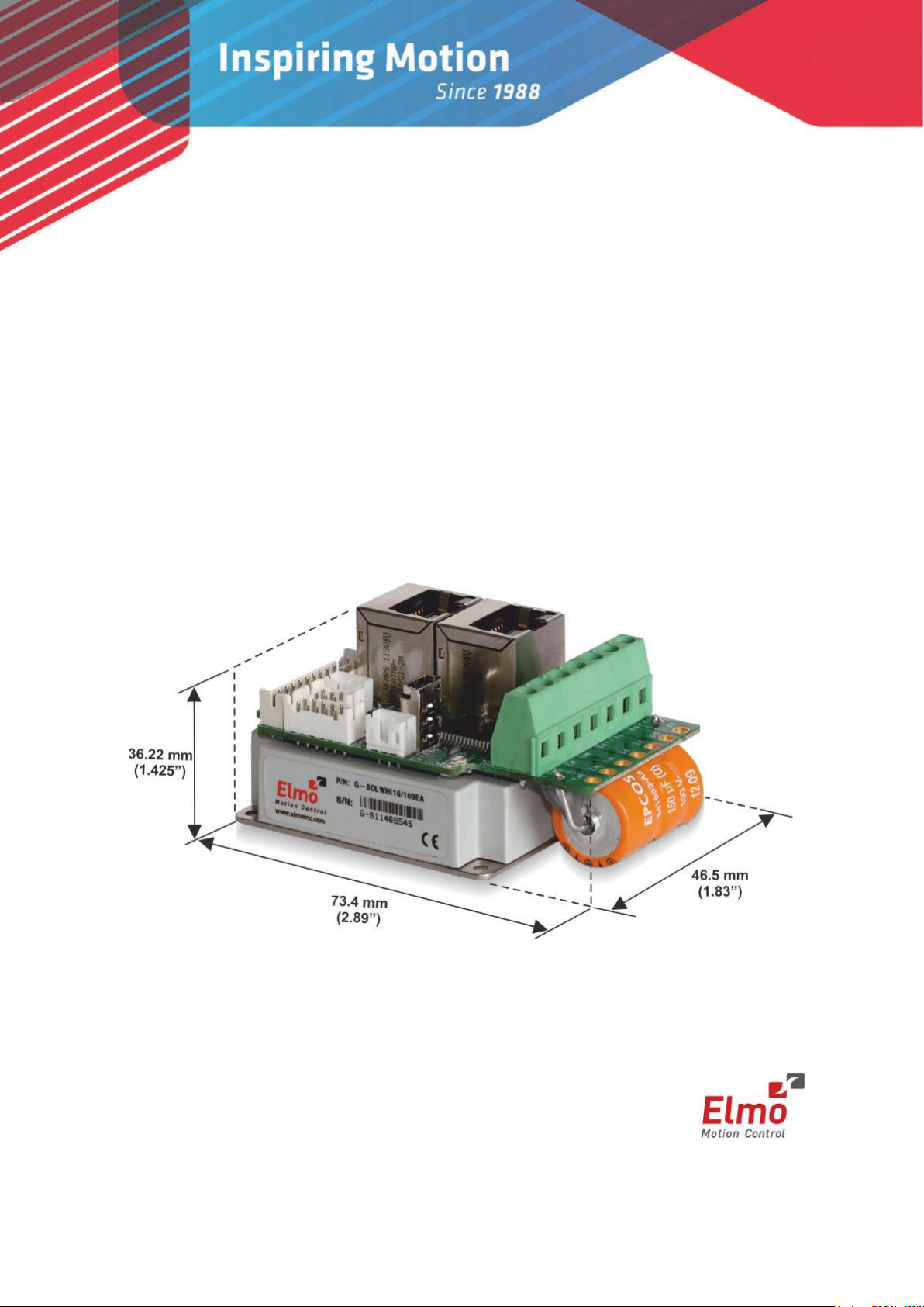
4.1. Physical Specification ..................................................................................................... 9
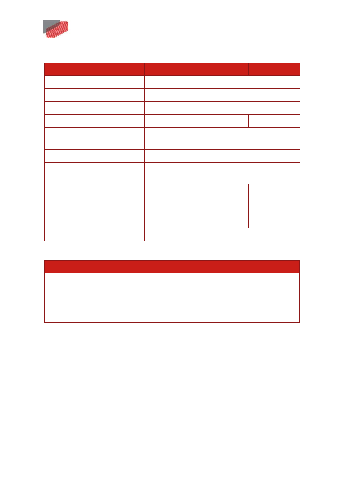
4.2. Technical Data ................................................................................................................ 9
4.2.1. Auxiliary Supply ............................................................................................. 10
4.2.2. Product Features ........................................................................................... 11
4.3. Environmental Conditions............................................................................................ 12
4.3.1. Gold Line........................................................................................................ 12
4.4. Gold Line Standards...................................................................................................... 13
Chapter 5: Installation....................................................................................................14
5.1. Unpacking the Drive Components ............................................................................... 14
5.2. Connector Types........................................................................................................... 15
5.2.1. Connector Types............................................................................................ 15
5.3. Mounting the Gold Solo Whistle .................................................................................. 17
5.4. The Gold Solo Whistle Connection Diagrams............................................................... 18
Chapter 6: Wiring...........................................................................................................20
6.1. Basic Recommendations .............................................................................................. 22
6.1.1. General .......................................................................................................... 22
6.1.2. Feedback Cable Port A and Port B Connector............................................... 23
6.1.3. Feedback Cable Port C Connector ................................................................. 24
6.1.4. IO Cable Connector........................................................................................ 24
6.1.5. STO (Port C) Cable Connector........................................................................ 25
6.2. Motor Power Connector Pinouts (J28)......................................................................... 26
6.3. Main and Auxiliary Power ............................................................................................ 28
6.3.1. Description .................................................................................................... 28
6.3.2. Main Power (J29)........................................................................................... 29
6.3.3. Auxiliary Power Supply (J30) ......................................................................... 30
6.3.4. Connectivity................................................................................................... 31
6.3.4.1. Power Rating 200 V ...................................................................... 31
6.3.4.2. Power Rating 100 V ...................................................................... 32
6.4. Drive Status Indicator................................................................................................... 34

Table of Contents
MAN-G-SOLWHIIG-EC (Ver. 1.509)
5
6.5. STO (Safe Torque Off) (J26) .......................................................................................... 35
6.5.1. Source Mode – PLC Voltage Level ................................................................. 36
6.5.2. TTL Mode – TTL Voltage Level ....................................................................... 36
6.6. Port A Connector (J4) ................................................................................................... 37
6.6.1. Incremental Encoder ..................................................................................... 38
6.6.2. Halls Sensor ................................................................................................... 38
6.6.3. Absolute Serial Encoder................................................................................. 39
6.6.3.1. Hiperface ...................................................................................... 40
6.7. Port B Connector (J5) ................................................................................................... 41
6.7.1. Incremental Encoder ..................................................................................... 42
6.7.2. Interpolated Analog Encoder ........................................................................ 43
6.7.3. Resolver ......................................................................................................... 44
6.8. Port C, Digital I/Os, and Analog Inputs (J6) .................................................................. 45
6.8.1. Port C – Emulated Encoder Output ............................................................... 47
6.8.2. Analog Input .................................................................................................. 48
6.8.3. Digital Input and Output TTL Mode............................................................... 49
6.8.4. Digital Input and Output PLC Source Mode .................................................. 51
6.9. USB 2.0 (J9)................................................................................................................... 53
6.10. RS-232 Connector (J21) ................................................................................................ 54
6.11. EtherCAT Communications Version ............................................................................. 55
6.11.1. EtherCAT IN/Ethernet Connector (J7) ........................................................... 55
6.11.2. EtherCAT OUT Connector (J8) ....................................................................... 56
6.11.3. EtherCAT Wiring ............................................................................................ 56
6.11.4. EtherCAT Status Indicator ............................................................................. 57
6.12. CAN Communications Version ..................................................................................... 58
6.12.1. CAN Wiring .................................................................................................... 59
6.13. Powering Up ................................................................................................................. 60
6.14. Initializing the System .................................................................................................. 60
6.15. Heat Dissipation ........................................................................................................... 61
6.15.1. Thermal Data ................................................................................................. 61
6.15.2. Heat Dissipation Data .................................................................................... 61
6.15.3. How to Use the Charts................................................................................... 62
Chapter 7: Dimensions ...................................................................................................63

Gold Solo Whistle Installation Guide
MAN-G-SOLWHIIG-EC (Ver. 1.509)
||Warnings|www.elmomc.com
6
Table of Contents
Chapter 1:
This Installation Guide
This installation Guide details the technical data, pinouts, and power connectivity of the Gold Solo
Whistle. For a comprehensive detailed description of the functions refer to the
MAN-G-Panel Mounted Drives Hardware manual which describes Panel Mounted products.
Chapter 2:
Safety Information
In order to achieve the optimum, safe operation of the Gold Solo Whistle, it is imperative that you
implement the safety procedures included in this installation guide. This information is provided to
protect you and to keep your work area safe when operating the Gold Solo Whistle and
accompanying equipment.
Please read this chapter carefully before you begin the installation process.
Before you start, ensure that all system components are connected to earth ground. Electrical
safety is provided through a low-resistance earth connection.
Only qualified personnel may install, adjust, maintain and repair the servo drive. A qualified person
has the knowledge and authorization to perform tasks such as transporting, assembling, installing,
commissioning and operating motors.
The Gold Solo Whistle contains electrostatic-sensitive components that can be damaged if handled
incorrectly. To prevent any electrostatic damage, avoid contact with highly insulating materials,
such as plastic film and synthetic fabrics. Place the product on a conductive surface and ground
yourself in order to discharge any possible static electricity build-up.
To avoid any potential hazards that may cause severe personal injury or damage to the product
during operation, keep all covers and cabinet doors shut.
The following safety symbols are used in this and all Elmo Motion Control manuals:
Warning:
This information is needed to avoid a safety hazard, which might cause bodily injury
or death as a result of incorrect operation.
Caution:
This information is necessary to prevent bodily injury, damage to the product or to
other equipment.
Important:
Identifies information that is critical for successful application and understanding of
the product.

Gold Solo Whistle Installation Guide
MAN-G-SOLWHIIG-EC (Ver. 1.509)
|Warnings|www.elmomc.com
7
Table of Contents
2.1. Warnings
•To avoid electric arcing and hazards to personnel and electrical contacts, never
connect/disconnect the servo drive while the power source is on.
•Power cables can carry a high voltage, even when the motor is not in motion. Disconnect
the Gold Solo Whistle from all voltage sources before servicing.
•The high voltage products within the Gold Line range contain grounding conduits for electric
current protection. Any disruption to these conduits may cause the instrument to become
hot (live) and dangerous.
•After shutting off the power and removing the power source from your equipment, wait at
least 1 minute before touching or disconnecting parts of the equipment that are normally
loaded with electrical charges (such as capacitors or contacts). Measuring the electrical
contact points with a meter, before touching the equipment, is recommended.
2.2. Cautions
•The maximum DC power supply connected to the instrument must comply with the
parameters outlined in this guide.
•When connecting the Gold Solo Whistle to an approved isolated auxiliary power supply,
connect it through a line that is separated from hazardous live voltages using reinforced or
double insulation in accordance with approved safety standards.
•Before switching on the Gold Solo Whistle, verify that all safety precautions have been
observed and that the installation procedures in this manual have been followed.
•Make sure that the Safe Torque Off is operational
2.3. CE Marking Conformance
The Gold Solo Whistle is intended for incorporation in a machine or end product. The actual end
product must comply with all safety aspects of the relevant requirements of the European Safety of
Machinery Directive 2006/42/EC as amended, and with those of the most recent versions of
standards EN 60204-1 and EN ISO 12100 at the least, and in accordance with 2006/95/EC.
Concerning electrical equipment designed for use within certain voltage limits, the Gold Solo
Whistle meets the provisions outlined in 2006/95/EC. The party responsible for ensuring that the
equipment meets the limits required by EMC regulations is the manufacturer of the end product.
2.4. Warranty Information
The products covered in this manual are warranted to be free of defects in material and
workmanship and conform to the specifications stated either within this document or in the
product catalog description. All Elmo drives are warranted for a period of 12 months from the date
of shipment. No other warranties, expressed or implied — and including a warranty of
merchantability and fitness for a particular purpose — extend beyond this warranty.

Gold Solo Whistle Installation Guide
MAN-G-SOLWHIIG-EC (Ver. 1.509)
|Warranty Information|www.elmomc.com
8
Table of Contents
Chapter 3:
Product Description
The Gold Solo Whistle is an integrated solution delivering up to 1.6 kWof continuous power or
3.2 kW of peak power in a compact package (73.4 x 46.5 x 36.22 mm or 2.89" x 1.83" x 1.425"), and
designed to simply and efficiently connect Elmo’s Gold Whistle servo drive directly to the
application. The solution consists of the Gold Whistle together with a convenient connection
interface which either eliminates or reduces development time and resources when designing an
application’s PCB board.
This advanced, high power density servo drive provides top performance, advanced networking and
built-in safety, as well as a fully featured motion controller and local intelligence. The Gold Solo
Whistle is powered by a single 12 V – 195 V isolated DC power source (not included) and a “smart”
control-supply algorithm enables the drive to operate up to 95V with only one power supply with
no need for an auxiliary power supply for the logic.
The drive can operate as a stand-alone device or as part of a multi-axis system in a distributed
configuration on a real-time network.
The Gold Solo Whistle drive is easily set up and tuned using Elmo Application Studio (EASII) software
tools. As part of the Gold product line, it is fully programmable with the Elmo motion control
language. For more about software tools refer to the Elmo Application Studio Software Manual.
The Gold Solo Whistle is available in a variety of options. There are multiple power rating options,
two different communications options – Standard (S suffix in the part number) or EtherCAT (E suffix
in the part number), a variety of feedback selections and I/O configuration possibilities.
3.1.1. Accessories
Cable Kit, catalog number: CBL-GSOLWHIKIT01 (can be ordered separately)
For further details, see the documentation for this cable kit (MAN-CBLKIT-GSOLWHI.pdf).

Gold Solo Whistle Installation Guide
MAN-G-SOLWHIIG-EC (Ver. 1.509)
|Physical Specification|www.elmomc.com
9
Table of Contents
Chapter 4:
Technical Information
4.1. Physical Specification
Feature Units All Types
Weight g (oz) 106 g (3.74 oz)
Dimension mm (in) 73.4 x 46.5 x 36.22 mm (2.89" x 1.83" x 1.425")
Mounting method Panel Mounted
4.2. Technical Data
Feature Units 1/100 2.5/100 5/100 10/100 15/100 20/100
Minimum supply voltage VDC 12
Nominal supply voltage VDC 85
Maximum supply voltage VDC 95
Maximum continuous power
output
W 80 200 400 800 1200 1600
Efficiency at rated power (at
nominal conditions)
% > 99
Maximum output voltage > 95% of DC bus voltage at f = 22 kHz
Auxiliary power supply VDC 12 to 95 VDC
(up to 6 VA inc. 5 V/2 x 200 mA for encoder)
Amplitude sinusoidal/DC
continuous current
A 1.0 2.5 5 10 15 20
Sinusoidal continuous RMS
current limit (Ic)
A 0.7 1.8 3.5 7 10.6 14.1
Peak current limit A 2 x Ic
Table 1: Power Rating
Note on current ratings: The current ratings of the Gold Solo Whistle are given in units of DC
amperes (ratings that are used for trapezoidal commutation or DC motors). The RMS (sinusoidal
commutation) value is the DC value divided by 1.41.

Gold Solo Whistle Installation Guide
MAN-G-SOLWHIIG-EC (Ver. 1.509)
|Technical Data|www.elmomc.com
10
Table of Contents
Elmo now offers a 200 VDC maximum output rating selection of Gold Solo Whistle, according to the
following technical data:
Feature Units 3/200 6/200 9/200
Minimum supply voltage VDC 12
Nominal supply voltage VDC 170
Maximum supply voltage VDC 195
Maximum continuous power output W 480 960 1450
Efficiency at rated power (at
nominal conditions)
% > 99
Maximum output voltage > 95% of DC bus voltage at f = 22 kHz
Auxiliary power supply VDC 12 to 95 VDC
(up to 6 VA inc. 5 V/2 x 200 mA for encoder)
Amplitude sinusoidal/DC
continuous current
A 3 6 9
Sinusoidal continuous RMS current
limit (Ic)
A 2.1 4.2 6.3
Peak current limit A 2 x Ic
4.2.1. Auxiliary Supply
Feature Details
Auxiliary power supply Isolated DC source only
Auxiliary supply input voltage 12 to 95 V
Auxiliary supply input power ≤ 4 VA without external loading
≤ 6 VA with full external loading

Gold Solo Whistle Installation Guide
MAN-G-SOLWHIIG-EC (Ver. 1.509)
|Technical Data|www.elmomc.com
11
Table of Contents
4.2.2. Product Features
Main Feature Details Presence and No.
STO TTL, or √
PLC Source √
Digital Input TTL, or 6
PLC Source 6
Digital Output TTL, or 2
PLC Source 2
Analog Input Differential ±10V 1
Feedback Standard Port A, B, & C √
Communication
Option
USB √
EtherCAT √
CAN √
RS-232 √

Gold Solo Whistle Installation Guide
MAN-G-SOLWHIIG-EC (Ver. 1.509)
|Environmental Conditions|www.elmomc.com
12
Table of Contents
4.3. Environmental Conditions
You can guarantee the safe operation of the Gold Solo Whistle by ensuring that it is installed in an
appropriate environment.
4.3.1. Gold Line
Feature Details
Operating ambient temperature
according to IEC60068-2-2
0 °C to 40 °C (32 °F to 104 °F)
Storage temperature -20 °C to +85 °C ( -4 °F to +185 °F)
Maximum non-condensing humidity
according to IEC60068-2-78
95%
Maximum Operating Altitude 2,000 m (6562 feet)
It should be noted that servo drives capable of
higher operating altitudes are available on
request.
Mechanical Shock
according to IEC60068-2-27
15g / 11ms Half Sine
Vibration
according to IEC60068-2-6
5 Hz ≤ f ≤ 10 Hz: ±10mm
10 Hz ≤ f ≤ 57 Hz: 4G
57 Hz ≤ f ≤ 500 Hz:5G

Gold Solo Whistle Installation Guide
MAN-G-SOLWHIIG-EC (Ver. 1.509)
|Gold Line Standards|www.elmomc.com
13
Table of Contents
4.4. Gold Line Standards
The following table describes the Main Standards of the Gold Solo Whistle servo drive. For further
details refer to the MAN-G-Panel Mounted Drives Hardware manual.
Main Standards Item
The related standards below apply to the performance of the servo drives as stated in the
environmental conditions in section 4.3.1 Gold Line above.
STO IEC 61800-5-2:2007 SIL 3 Adjustable speed electrical power drive systems –
Safety requirements – Functional
EN ISO 13849-1:2008 PL e, Cat 3 Safety of machinery — Safety-related parts of control
systems.
Approved IEC/EN 61800-5-1 Adjustable speed electrical power drive systems
Safety requirements – Electrical, thermal and energy
Recognized UL61800-5-1 Adjustable speed electrical power drive systems
Safety requirements – Electrical, thermal and energy
Recognized UL 508C Power Conversion Equipment
In compliance with UL 840 Insulation Coordination Including Clearances and
Creepage Distances for Electrical Equipment
Conformity with CE 2006/95/EC Low-voltage directive 2006/95/EC
Recognized CSA C22.2 NO. 14-13 Industrial Control Equipment

Gold Solo Whistle Installation Guide
MAN-G-SOLWHIIG-EC (Ver. 1.509)
||Unpacking the Drive Components|www.elmomc.com
14
Table of Contents
Chapter 5:
Installation
The Gold Solo Whistle must be installed in a suitable environment and properly connected to its
voltage supplies and the motor.
5.1. Unpacking the Drive Components
Before you begin working with the Gold Solo Whistle, verify that you have all of its components, as
follows:
•The Gold Solo Whistle servo drive
•The Elmo Application Studio software and software manual
The Gold Solo Whistle is shipped in a cardboard box with Styrofoam protection.
To unpack the Gold Solo Whistle:
1. Carefully remove the servo drive from the box and the Styrofoam.
2. Check the drive to ensure that there is no visible damage to the instrument. If any damage
has occurred, report it immediately to the carrier that delivered your drive.
3. To ensure that the Gold Solo Whistle you have unpacked is the appropriate type for your
requirements, locate the part number sticker on the side of the Gold Solo Whistle. It looks
like this:
4. Verify that the Gold Solo Whistle type is the one that you ordered, and ensure that the
voltage meets your specific requirements.
The part number at the top provides the type designation. Refer to the appropriate part
number in the section Catalog Number at the beginning of the installation guide.
The part number of the Gold Solo Whistle (EtherCAT version) has an E, for example, G-
SOLWHI10/100E whereas the CAN version has an S, for example G- SOLWHI10/100S.
There are two models of the Gold Solo Whistle: connectors only (for currents of 10 A or less) and
wires only (for currents of 15 A or more). On request, the wires model may be ordered for currents
of 10 A or less.

Gold Solo Whistle Installation Guide
MAN-G-SOLWHIIG-EC (Ver. 1.509)
|Connector Types|www.elmomc.com
15
Table of Contents
5.2. Connector Types
The Gold Solo Whistle has twelve connectors (connectors' version).
5.2.1. Connector Types
Port No. Pins Type Function
M1, M2, M3,
PE
4 5.08 mm pitch Motor phases
(Connectors version)
VP+, PR, PE 3 5.08 mm pitch Power (Connectors version)
Wires 7 14 AWG
(M1,M2,M3,PR,VP+)
16 AWG (PE)
Main Power and Motor Power
(Wires version)
J4 2x6 2.0 mm pitch Feedback port A
J5 2x4 2.0 mm pitch Feedback port B
J6 2x12 2.0 mm pitch I/O and port C
J9 5 USB Device Mini-B Mini-USB type B
J21 3 2.0 mm pitch RS-232 communication
J26 3 2.0 mm pitch STO
J27 2 2.0 mm pitch Reserved
J30 (PR, VL) 2 2.0 mm pitch Auxiliary supply input
EtherCAT Version
J7 8 RJ-45 EtherCAT in
J8 8 RJ-45 EtherCAT out
CAN Version
J22 4 2.0 mm pitch CAN
J23 4 2.0 mm pitch CAN

Gold Solo Whistle Installation Guide
MAN-G-SOLWHIIG-EC (Ver. 1.509)
|Connector Types|www.elmomc.com
16
Table of Contents
Figure 1: Connector Locations – EtherCAT
Figure 2: Connector Locations – CAN
Table 2: Connector Types
The pinouts in Chapter 6: Wiring describe the function of each pin in the Gold Solo Whistle
connectors that are listed in Table 2.

Gold Solo Whistle Installation Guide
MAN-G-SOLWHIIG-EC (Ver. 1.509)
|Mounting the Gold Solo Whistle|www.elmomc.com
17
Table of Contents
5.3. Mounting the Gold Solo Whistle
The Gold Solo Whistle was designed for mounting on a surface. When integrating the Gold Solo
Whistle into a device, be sure to leave about 1 cm (0.4") outward from the heat-sink to enable free
air convection around the drive. If the Gold Solo Whistle is enclosed in a metal chassis, we
recommend that the Gold Solo Whistle be screw-mounted to it to help with heat dissipation. The
Gold Solo Whistle has screw-mount holes on each corner of the heat-sink for this purpose – see
below.
Figure 3: Mounting the Gold Solo Whistle
When the Gold Solo Whistle is not connected to a metal chassis, the application’s thermal profile
may require a solution for heat dissipation due to insufficient air convection. In this case, we
recommend that you connect an external heat-sink. Elmo has an external heat-sink (Catalog
number: WHI-HEATSINK-2) that can be ordered for this purpose – see below.
Figure 4: Gold Solo Whistle External Heat-sink

Gold Solo Whistle Installation Guide
MAN-G-SOLWHIIG-EC (Ver. 1.509)
|The Gold Solo Whistle Connection Diagrams|www.elmomc.com
18
Table of Contents
5.4. The Gold Solo Whistle Connection Diagrams
Figure 5: The Gold Solo Whistle Connection Diagram - EtherCAT

Gold Solo Whistle Installation Guide
MAN-G-SOLWHIIG-EC (Ver. 1.509)
|The Gold Solo Whistle Connection Diagrams|www.elmomc.com
19
Table of Contents
Figure 6: The Gold Solo Whistle Connection Diagram – CAN

Gold Solo Whistle Installation Guide
MAN-G-SOLWHIIG-EC (Ver. 1.509)
|The Gold Solo Whistle Connection Diagrams|www.elmomc.com
20
Table of Contents
Chapter 6:
Wiring
Once the product is mounted, you are ready to wire the device. Proper wiring, grounding and
shielding are essential for ensuring safe, immune and optimal servo performance of the drive.
The following table legend describes the wiring symbols detailed in all installation guides.
Wiring Symbol Description
Earth connection (PE)
Earth Connection
Common at the Controller
Shielded cable with drain wire.
The drain wire is a non-insulated wire
that is in direct contact with the braid
(shielding).
Shielded cable with drain wire
significantly simplifies the wiring and
earthing.
Shielded cable braid only, without
drain wire.
Twisted-pair wires
Analog Ground
This manual suits for next models
2
Other Elmo Servo Drive manuals

Elmo
Elmo TUB Series User manual

Elmo
Elmo Gold Whistle Series User manual

Elmo
Elmo Gold Drum HV User manual

Elmo
Elmo Cello User manual

Elmo
Elmo Gold DC Whistle Series User manual

Elmo
Elmo Gold Series User manual

Elmo
Elmo SimplIQ Series User manual

Elmo
Elmo 30/60 User manual

Elmo
Elmo Gold DC Bell User manual

Elmo
Elmo Gold DC Trombone User manual
Popular Servo Drive manuals by other brands

Lenze
Lenze L-force 9400 Hardware manual

Parker
Parker FL-20-C Series product manual

Allen-Bradley
Allen-Bradley Kinetix 5100 2198-E1004-ERS user manual

LinMot
LinMot E1450-PL-QN-0S installation guide

Mitsubishi Electric
Mitsubishi Electric MR-J4-*B-RJ010 Series instruction manual

BONFIGLIOLI
BONFIGLIOLI Profinet DGM Series operating manual