ELNA Cover Pro 2000CPX Troubleshooting guide

SERVICE MANUAL
&
PARTS LIST
MODEL: Cover Pro 2000CPX

Replacing the External Parts
1. Belt Cover........................................................................................ 1
2. Looper Cover................................................................................... 2
3. Rear Cover ...................................................................................... 3
4. Front Cover...................................................................................... 4
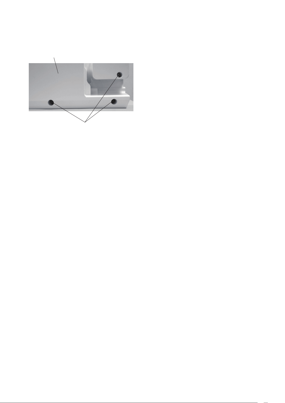
5. Free Arm Cover ............................................................................... 5
Mechanical Adjustment
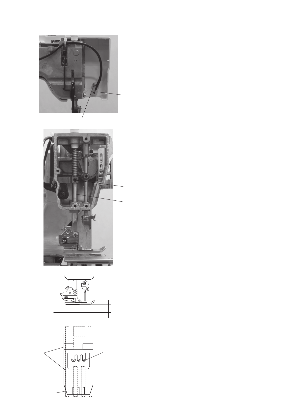
1. Presser Bar Height .......................................................................... 6
2. Foot Pressure .................................................................................. 7
3. Needle Bar Heihgt ........................................................................... 8
4. Feed Dog Height ............................................................................. 9
5. Looper Height................................................................................ 10
6. Looper Postion .............................................................................. 11
7. Needle to Looper Timing ............................................................... 12
8. Clearance between the Needle and Looper.................................. 13
9. Back Needle Guard Height............................................................ 14
10. Needle to Feed Dogs Timing ......................................................... 15
11. Stitch Length ................................................................................. 16
12. Differential Feed Ratio................................................................... 17
13. Thread Tension.............................................................................. 18
14. Motor ............................................................................................. 19
Parts List ........................................................................................... 20-37
Table of Contents

1
Replacing the External Parts
1. Belt Cover
To remove:
zRemove the setscrews qand remove the belt
cover
w.
To attach:
xFollow the above procedures in reverse.
q
q
w

2
2. Looper Cover
To remove:
zRemove the setscrews qand remove the
looper cover w(with a hinge attached).
To attach:
xFollow the above procedures in reverse.
q
w

3
3. Rear Cover
To remove:
zRaise the handle qand remove the setscrews w, e
and
r. Remove the rear cover t.
To attach:
xFollow the above procedures in reverse.
q
w
e
r
t

4
4. Front Cover
To remove:
zRemove the face plate, belt cover, looper cover and
rear cover.
xRemove the setscrews q, w, eand r.
Remove the front cover t.
To attach:
cFollow the above procedures in reverse.
q
e
rt
w

5
5. Free Arm Cover
To remove:
zRemove the setscrews qand the free arm cover w.
To attach:
xFollow the above procedures in reverse.
q
w

6
Mechanical Adjustment
1. Presser Bar Height
The distance between the bottom of the presser foot in
up position and the needle plate should be 4.7–5.3 mm.
zRemove the face plate and front cover.
xRemove the setscrews q, and lamp set plate w.
cRaise the presser foot and loosen the setscrew e.
Move the presser bar rup or down to set the
presser foot height to 5 mm.
vTighten the setscrew efirmly.
NOTE:
Make sure that the presser foot should be parallel to
the feed dog slots tin the needle plate and should not
interfare with the needles.
bAttach the lamp set plate, front cover and face plate.
w
e
r
t
q
4.7–5.3 mm
Should be
parallel.
Should not interfare

7
2. Foot Pressure
The pressure adjusting screw should protrude 10 mm
from the top of the machine.
zTurn the adjusting screw qto set its height at 10 mm.
10 mm
q

8
3. Needle Bar Height
The distance between the point of the left needle
(Schmetz ELx705, size 80/12) and the upper surface of
the needle plate should be 7.8–8.2 mm when the needle
bar is at the highest position.
zRemove the face plate and front cover.
xRemove the setscrews qand lamp set plate w.
cReplace the left needle with Schmetz ELx705, size
80/12 needle e.
vTurn the handwheel toward you to raise the needle
bar to the highest position.
bLoosen the setscrew rand move the needle bar t
up or down to adjust the distance at 8.0 mm.
NOTE:
Be sure not to rotate the needle bar when adjusting the
needle bar height.
nTighten the setscrew rand attach the lamp set
plate.
mAttach the face plate and front cover.
e
r
7.8–8.2 mm
t
w
q

9
4. Feed Dog Height
Turn the handwheel toward you to raise the feed dog to
its highest position.
When the presser foot is lowered, the maximum height
of the feed dog should be 0.75-0.95 mm above the
needle plate.
zSet the stitch length dial at 3and differential feed dial
at
1.0.
xLower the presser foot and turn the handwheel
toward you to raise the feed dog to its highest
position.
cOpen the looper cover and loosen the setscrews q.
vMove the main wand sub efeed dogs up or down
to set the height at 1.0 mm.
bTighten the setscrews qfirmly.
0.75-0.95 mm
q
we
q

10
5. Looper Height
The height of the looper point should be 72.6–73.0 mm.
zRemove the free arm cover and needle plate.
xReplace the right needle with the short test pin
(28.8 mm long) q.
cTurn the handwheel toward you to bring the looper w
to its rightmost position.
vPull the looper release knob eand swing the
looper
wto the left until its point matches with the
test pin q.
bLoosen the setscrew rand move the looper up or
down to match its point twith the tip yof the test
pin.
nTighten the setscrew rfirmly.
mReplace the test pin with a regular needle.
Attach the needle plate and free arm cover.
q
w
e
r
t
72.6–73.0 mm
y

11
6. Looper Position
The distance between the looper point and center of
the right needle should be 1.8–2.2 mm when the looper
is at its rightmost position.
zRemove the free arm cover and needle plate.
xReplace the right needle with the short test pin
(28.8 mm long) q.
cTurn the handwheel toward you to bring the looper w
to its rightmost position.
vLoosen the setscrew eand move the looper to the
left or right to adjust the distance between the test
pin and looper point to 2.0 mm.
NOTES:
Do not move the looper up or down, otherwise the
looper height will change.
Use a stem rof the regular needle to check if there is a
proper gap between the looper point and test pin
nTighten the setscrew efirmly.
mReplace the test pin with a regular needle.
Attach the needle plate and free arm cover.
q
w
e
r
1.8–2.2 mm

12
7. Needle to Looper Timing
When the point of the looper meets with the right side of
the needle on the right, the needle bar rises 1.3-1.5 mm
from the lowest position.
zRemove the free arm cover and needle plate.
xReplace the right needle with the long test pin
(30.24 mm long) q.
cTurn the handwheel toward you until the looper
point
wmeets with the right side of the test pin.
vLoosen the setscrews eand turn the looper rocking
cam
rto match the looper point with the tip of the
test pin.
•Ifthetimingistooearlyt, turn the cam in the
direction
A.
•Ifthetimingistoolatey, turn the cam in the
direction
B.
bTighten the setscrews efirmly.
nReplace the test pin with a regular needle.
Attach the needle plate and free arm cover.
q
w
e
r
t
y
A
B

13
8. Clearance between the Needle and
Looper
The clearance between the looper point and scarf of
the needle (Schmetz ELx705, size 80/12) should be
0–0.05 mm.
zRemove the free arm cover and needle plate.
xTurn the handwheel toward you until the looper
point
qcomes behind the needle.
cLoosen the setscrews wand thrust the front needle
guard
eagainst the needle to make 0-0.05 mm
clearance between the needle and looper point.
vTighten the setscrews wand check the clearance.
bAttach the needle plate and free arm cover.
q
w
e
e
0–0.05 mm

14
9. Back Needle Guard Height
The upper edge of the back needle guard should be
2.6–3.0 mm below the lower edge of the looper point
when the looper point meets with the right side of the
needle.
zRemove the free arm cover and needle plate.
xTurn the handwheel toward you until the looper
point
qmatches with the right side of the needle.
cLoosen the setscrews wand move the back needle
guard
eup or down to set the upper edge r2.8 mm
below the lower edge tof the looper point.
vTurn the handwheel toward you slightly to bring the
looper point behind the needle.
Check the clearance between the back needle guard
and the needle (Schmetz ELx705, size 80/12).
Itshouldbe0.1–0.3mm.
NOTE:
Iftheclearanceisoutofstandardrange,adjustitby
re-positioning the front needle guard. However, the
clearance between the looper point and needle
should be 0–0.05 mm.
bTighten the setscrews w.
nAttach the needle plate and free arm cover.
q
w
e
r
t
e
0.1–0.3 mm
2.6–3.0 mm
0–0.05 mm

15
10. Needle to Feed Dogs Timing
The point of the left needle should be 2.9–3.1 mm above
the upper surface of the needle plate when the top of the
feed dogs are level with the upper surface of the needle
plate in downward motion.
zRemove the free arm cover and rear cover.
xSet the stitch length dial at 3and differential feed dial
at
1.0.
cTurn the handwheel toward you to lower the needle
bar until the point of the left needle is 3.0 mm above
the upper surface of the needle plate q.
vLoosen the setscrews wand turn the feed cam eto
adjust the height of the feed dogs.
•Ifthetopofthefeeddogsarehigherthanuppersurface
of the needle plate, turn the feed cam in the direction A.
•Ifthetopofthefeeddogsarelowerthanuppersurface
of the needle plate, turn the feed cam in the direction B.
bTighten the setscrews w.
Attach the rear cover and free arm cover.
q
w
e
w
A
B
2.9–3.1 mm

16
11. Stitch Length
The stitch length should be 30–32 mm when the stitch
length dial is set at 3 and differential feed dial at 1.0.
zRemove the belt cover.
xSet the stitch length dial qat 3and differential feed
dial
wat 1.0.
cPlace a piece of paper under the presser foot.
Lower the foot and turn the handwheel toward you
about 15 times.
Measure the distance of needle marks of 10 stitches.
The distance should be 30–32 mm.
vTurn the adjusting screw eto adjust the stitch length.
•Ifthestitchlengthislongerthan32mm,turnthe
adjusting screw in the direction A.
•Ifthestitchlengthisshorterthan30mm,turnthe
adjusting screw in the direction B.
bAttach the belt cover.
eBA
30–32 mm (10 stitches)
q
w

17
12. Differential Feed Ratio
The main and sub feed dogs should move uniformly
together when the stitch length dial is set at 3 and
differential feed dial at 1.0.
zRemove the belt cover.
xSet the stitch length dial at 3and differential feed dial
at
1.0.
cTurn the adjusting screw qto adjust the differential
feed ratio.
•Ifthesub-feeddogmoveslessthanthemainfeeddog
does, turn the adjusting screw in the direction of A.
•Ifthesub-feeddogmovesmorethanthemainfeed
dog does, turn the adjusting screw in the direction of B.
NOTE:
When the differential feed ratio is properly adjusted, the
feed link wsits horizontally.
vAttach the belt cover.
q
w
BA

18
13. Thread Tension
The standard thread tension measured with the King
brand white polyester thread (#50) should be as follows:
qLeft needle thread: 65–75 grams (Dial set at 4)
wCenter needle thread: 55–65 grams (Dial set at 4)
eRight needle thread: 45–55 grams (Dial set at 4)
rLooper thread: 9–15 grams (Dial set at 3)
zRemove the front cover.
xTurn the adjusting plate tto adjust the tension.
• If the tension is too loose, turn the adjusting plate in
the direction of A.
• If the tension is too tight, turn the adjusting plate in the
direction of B.
cAttach the front cover.
t
q
w
er
A
B
Table of contents
Other ELNA Sewing Machine manuals

ELNA
ELNA 3210 JEANS - User manual

ELNA
ELNA 9900 - LEAFLET Technical manual

ELNA
ELNA 5100 - User manual

ELNA
ELNA 9500 - LEAFLET User manual

ELNA
ELNA eXcellence 680 User manual

ELNA
ELNA eXperience 660 User manual

ELNA
ELNA XPRESSIVE 2 User manual

ELNA
ELNA 5100 - User manual

ELNA
ELNA expressive 940 User manual

ELNA
ELNA eXcellence 790PRO User manual

ELNA
ELNA 500 CLUB User manual

ELNA
ELNA Elnita User manual

ELNA
ELNA 792D User manual

ELNA
ELNA eXcellence 782 User manual

ELNA
ELNA eXplore 150 User manual

ELNA
ELNA Plana Star de Luxe CI. User manual

ELNA
ELNA 7200 User manual

ELNA
ELNA eXcellence 730 User manual

ELNA
ELNA 6001 User manual

ELNA
ELNA eXperience 660 User manual