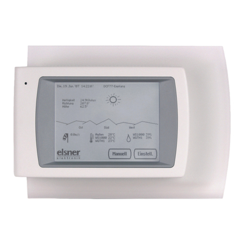
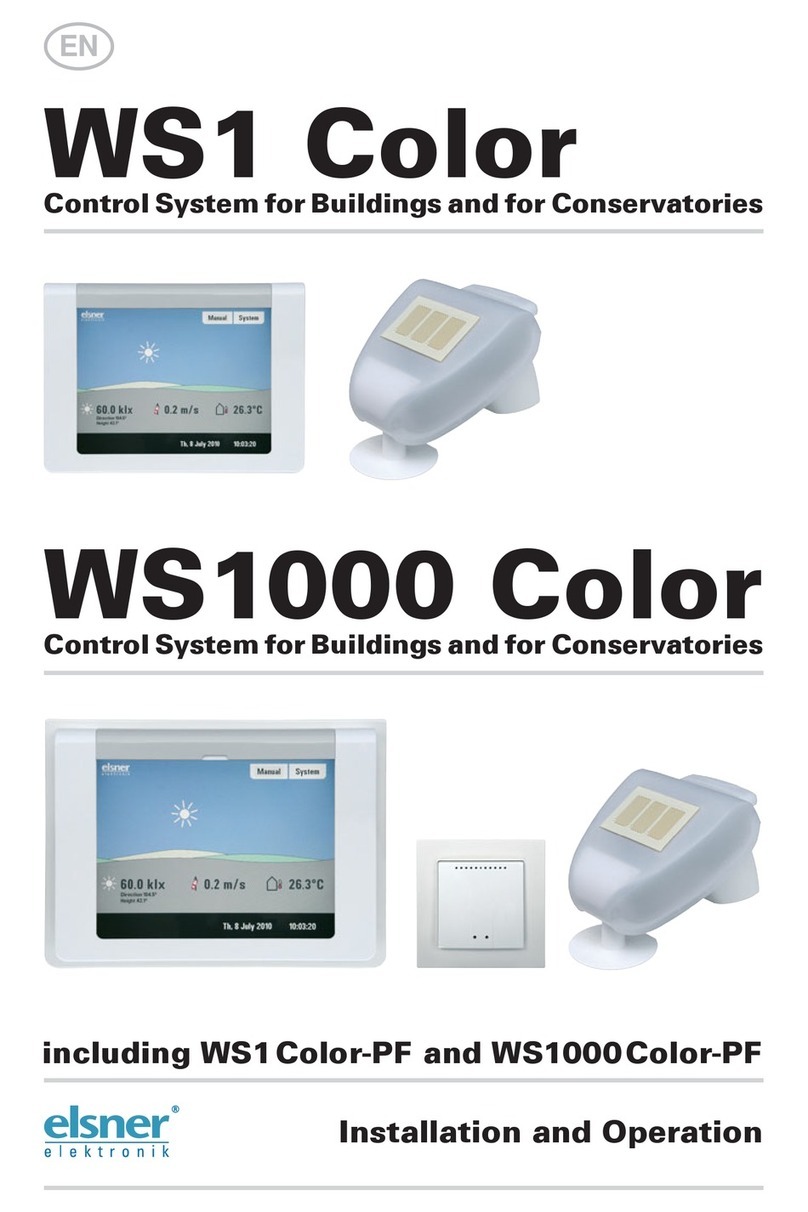
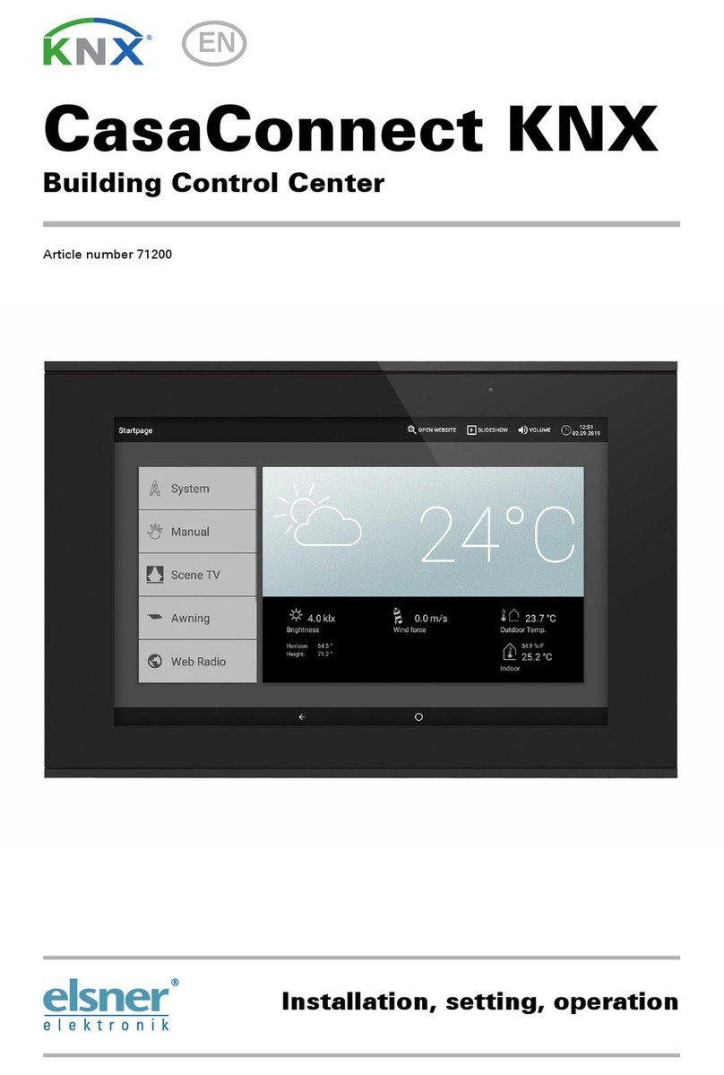
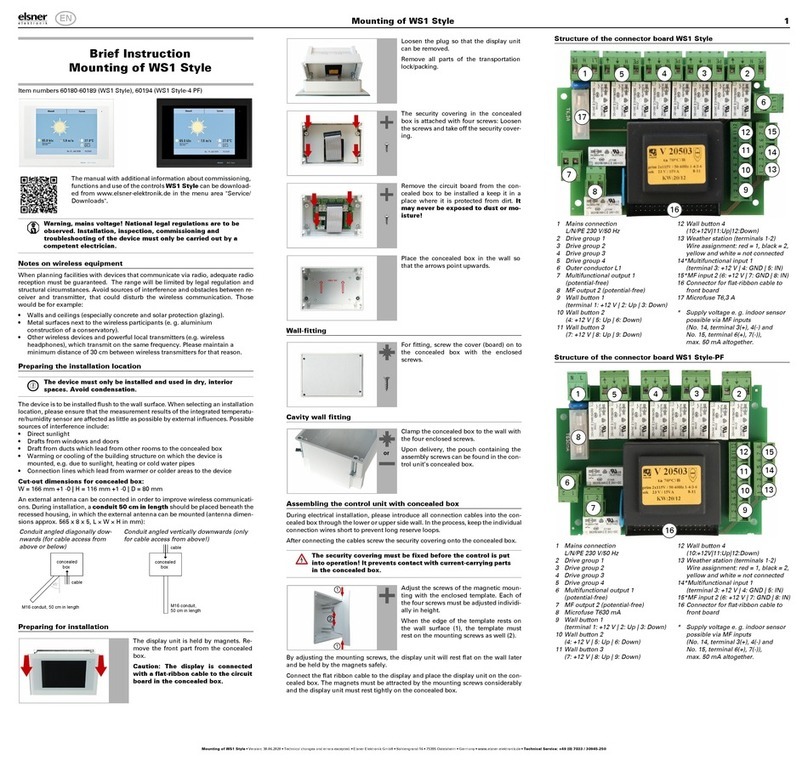
Elsner WS1 Color User manual

Control System WS1 Style / WS1000 Style 1
Control System WS1 Style / WS1000 Style • Version: 24.10.2023 • Technical changes and errors excepted. • Elsner Elektronik GmbH • Sohlengrund 16 • 75395 Ostelsheim • Germany • www.elsner-elektronik.de • Technical Service: +49 (0) 7033 / 30945-250
Control System WS1 Style /
WS1000 Style: First steps
Technical specifications and installation instructions
Item numbers 60180-60189 (WS1 Style), 60194 (WS1 Style-4 PF)
Item numbers 60201-60204, 60206-60209 (WS1000 Style),
60214 (WS1000 Style-10 PF)
Field of application
The control system was developed so that the different technical equipment instal-
led in conservatories and buildings could be centrally controlled. The control units
offer the highest measure of flexibility with regard to connections, allowing set-
tings to be optimally and individually adjusted to the circumstances on site. Please
use this operational guide to adjust the automatic functions to your requirements
and enable comfortable manual operation.
Connection and control options
The following environmental parameters will be measured and displayed:
• Outdoor and indoor temperature
• Air humidity inside
• Lighting (intensity and direction, twilight recognition)
• Wind speed
• Precipitation
•Time/date
The following drives can be connected to the drive outputs:
(WS1 Style: 0-4 drive outputs, WS1000 Style: 4-10 drive outputs)
• Electrically-operated awnings
• Electrically-operated blinds
• Electrically-operated shutters
• Electrically-operated windows and sliding roofs
• Electrically-operated sliding doors
The following devices can be connected to the multifunctional outputs:
(WS1 Style: 2 MF outputs, WS1000 Style: 4 MF outputs)
• Heating
• Cooling
• Alarm equipment
•Lighting
• Roof gutter heating
• Ventilation units
• Dimmer (for a light)
The following can be connected to the multifunctional inputs:
(WS1 Style: 2 MF inputs, WS1000 Style: 4 MF inputs)
• Motion detector
• Smoke detector
• Climate sensor (A climate or heating unit which is independent of the control
unit. Status query “active”/“not active”, for cancelling ventilation)
• Safety contacts to keep drives in secured position
• Closed-contact for closing notification of a sliding door
• Impulse for automatic reset (e.g. button or impulse at alarm activation)
• Binary contact
The following devices can be connected via a wireless connection:
• WGTH-UP indoor sensors for temperature and humidity measurement at
various places in the room. This allows various climate areas to be realised
(e. g. living and plant areas in the conservatory)
• WGT temperature sensor for temperature measurement at various places in
the room and, for example, in the ground for control of the floor heating
• Radio remote control Remo 8/pro, push buttons Corlo P RF, push button
interface RF-B2-UP
• Elsner ventilation devices (WL400, WL800, WL-Z)
• Fan module RF-VM for connecting fans/circulating air heating units from
other manufacturers
• RF relay (radio relay, On/Off)
• RF MSG (radio motor control device, Up/Down)
The following additional options are available:
• Connection of up to 10 external Up/Down wall buttons for manual operation
of drives and devices on the spot
• Presentation of a slide show on SD card, data storage on SD card
Delivery scope
• Central control and operations unit
WS1 Style: With integrated indoor sensor. With 1, 2, 3 or 4 drive outputs for
230 V motors or without drive outputs, depending on model.
WS1 Style-PF: With integrated indoor sensor. With 4 potential-free drive
outputs.
WS1000 Style: With 4, 6, 8 or 10 drive outputs for 230 V motors, depending
on model.
WS1000 Style-PF: With 10 potential-free drive outputs.
• Weather station
Additionally with WS1000 Color:
• WGTH-UP indoor sensor with frame
(You need a socket ø 60 mm, 42 mm deep additionally)
Commissioning
Installation notes
Installation, testing, operational start-up and troubleshooting should
only be performed by an authorised electrician.
DANGER!
Risk to life from live voltage (mains voltage)!
• Inspect the device for damage before installation. Only put undamaged
devices into operation.
• Comply with the locally applicable directives, regulations and provisions
for electrical installation.
• Immediately take the device or system out of service and secure it against
unintentional switch-on if risk-free operation is no longer guaranteed.
Use the device exclusively for building automation and observe the operating ins-
tructions. Improper use, modifications to the device or failure to observe the ope-
rating instructions will invalidate any warranty or guarantee claims.
Operate the device only as a fixed-site installation, i.e. only in assembled condition
and after conclusion of all installation and operational start-up tasks, and only in
the surroundings designated for it.
Elsner Elektronik is not liable for any changes in norms and standards which may
occur after publication of these operating instructions.
Procedure
Installation, testing, commissioning and fault repair should
only be carried out by a qualified electrician.
To install the control unit, proceed as follows:
• Installation
• Commissioning
• Basic setting in the menu System > Installation
• Automatic settings in the menu System > Automatic Settings
Weather data display (starting image)
As a starting image, the control system shows the current weather data:
Sun data
Wind
The wind speed will be shown in metres per second (m/s) and the windsock chan-
ges:
Outdoor temperature
Night-time Re-cooling, Frost Alarm and Window Movement Limitation are
displayed in turn next to the outdoor temperature value as long as the relevant
function is active.
3.3. Set night_time re-cooling (ventilation)
3.3. Adjust frost alarm
3.3. Set movement limitations (windows)
Indoor information
You may select which indoor information is displayed (e. g. if several sensors are
connected).
System > Installation > Weather Display
6.1. Indoor sensor for weather display
The touch display
Manual control, as well as setting the defaults for the automatic functions and the
connected equipment, is via the control’s stationary touch display. The button sur-
faces are operated in this area by touching the display. When a button is activated,
there is visual feedback and a brief audio signal sounds. The sound can be swit-
ched off.
System > WS1 / WS1000 Settings > Settings > Button tone
If the push buttons shown do not match up with the touch-sensitive surfaces (you
have to press “next to the button”), the touch display can be calibrated as follows.
System > WS1 / WS1000 Settings > Settings > Calibrate touch
Operating the display with long fingernails will not damage the screen or the touch
function. Touching the display with very hard or pointed objects (e.g. those made
from glass, gems or metal) should be avoided as this can cause marks.
The „Manual“ menu
You can reach the menu for manual control of drives and equipment by using the
button Manual:
Here you can operate all connected drives and devices directly: Use the buttons to
select the name of the drive or device you want to operate. You can change the or-
der of the list in the System menu.
The manual with additional information about commissioning,
functions and use of the controls WS1/WS1000 Style can be
downloaded from www.elsner-elektronik.de in the menu area
"Service/Downloads".
Intensity: Light intensity (brightness) in Lux (lx) or Kilolux (klx)
Direction: Direction (azimuth) in degrees
Height: Elevation over the horizon in degrees
Calm: up to 1.9 m/s
Slight wind: 2.0 to 9.9 m/s
Strong wind: 10.0 m/s and up
A caution flag appears besides the wind symbol if wind alarm
has been triggered for a drive.
Outdoor temperature at the weather station in degrees Celsius
(°C)
Temperature in degrees Celsius (°C)
Air humidity in %RH
EN

Control System WS1 Style / WS1000 Style 2
Control System WS1 Style / WS1000 Style • Version: 24.10.2023 • Technical changes and errors excepted. • Elsner Elektronik GmbH • Sohlengrund 16 • 75395 Ostelsheim • Germany • www.elsner-elektronik.de • Technical Service: +49 (0) 7033 / 30945-250
System > Installation > Channel Order
6.1. Define channel order
The selected device is marked in white. On the right-hand side you will receive sta-
tus information (e.g. on/off, open/closed, exhaust air level, error messages) and va-
rious control options (up/down arrow keys or on/off buttons).
The Down and Up buttons are fitted with automatic time functions.
Drives:
The drive can be precisely positioned with brief button presses (less than 1 second,
short audio signal). For shutters and roller blinds, only a short step-movement
command is triggered. If the button is pressed for longer than 1 second (higher au-
dio signal: locking signal), the drive moves independently to the end position. A
brief press in the opposite direction stops the drive.
For shades and windows, the movement position is shown in percent above the
Up-/Down buttons (for blinds, also the slat position). For radio motor control units,
the position shown can deviate from the movement position set in the automatic
mode by up to 2%.
Ventilation units WL400 and WL800:
Ventilation units WL400 and WL800 are operated in 10% steps by briefly pressing
the button (less than 1 second, brief sound, 10 ventilation levels). By pressing the
button longer, the fan speed is changed continuously. Release the button to stop
speed change.
Note: In rare cases, radio disturbances can lead to continuing speed change after
having released the button. Please briefly press the other direction then.
Block because of rain, wind or frost alarm:
If a drive group is momentarily blocked for manual operation by a rain, wind or
frost alarm, the arrow keys will be greyed out and may not be used. The message
“Rain alarm” and/or “Wind alarm” is shown.
The frost alarm can be deactivated by pressing the corresponding button (see dia-
gram); manual operation is then possible again. The frost block will then be first
active for this drive again when it is reactivated manually or the next time the frost
alarm is triggered.
ATTENTION
Material damage due to movement of frozen shading
elements!
The drive and hangings may be damaged if a firmly frozen outdoor
shading is moved!
• Make shure the rails are no longer frozen before manually
switching
off the frost alarm.
Whether a drive or device is in automatic mode or manually operated can be re-
cognised from the white marking on the buttons on the right and the text “Auto”
next to the name button in the list on the left. By pressing the button you can switch
from one to another.
After being operated manually the drive or device remains in manual mode. The
automatic functions are thus switched off and only the rain and wind protection
will be carried out. The equipment will only switch back into automatic mode when
reset by hand (“Manu” button) or through the daily automatic reset. In the Auto-
matic menu, the automatic reset can be activated separately for each drive group
and each device.
This button allows you to perform the automatic reset manually. All systems for
which an automatic reset has been set are then set to automatic mode.
Slideshow
The WS1 Style / WS1000 Style can play back digitally-stored image data as a
slideshow. For this, the image data must be saved onto an SD card and fulfil the
following requirements:
• Data format Bitmap (BMP)
• Size 640 x 480 pixels
• Color intensity 24 bit or 16 bit
• No compression (RLE)
• The data must be saved in the uppermost level of the card's directory (root
directory)
The SD card is pushed into the slot, until it clicks into place.
The card will automatically be recognised. If image data are stored on the card, the
symbol for „play-back“ appears at the bottom right-hand side of the weather data
display.
The image changes approx. every 45 seconds (for images with 24-bit color inten-
sity). To return to the weather data display, touch the screen or remove the SD card
(briefly press down on the card so that it pops out).
Further information about the image display can be found in chapter
6.2. Using an SD card
Navigation in the System menu
All settings for drives and devices, for the automation and the control system are
changed in the System menu, which you reach via the System button:
In three sub-menus you can carry out the following adjustments:
Installation:
• Specify fundamental characteristics of the drives at inputs/outputs
• Set up wireless connections to devices
• Define the order in which the drives and devices are shown (e.g. in the
manual menu)
Automatic settings:
• Define automatic functions for the individual drives and devices
• Adjust general automatic settings: Twilight value, movement delays, forced
closure, ventilation block and automatic reset
Control Settings:
• Change personal data such as Time/Date and location and adjust the screen
display to your personal preferences
• Restart the control unit, reset to factory defaults and change internal settings
• Set an access code to protect the “Installation” and “Automatic Settings”
menus from unauthorised changes.
The following buttons are needed constantly for navigation in the System menu:
On the top right, beneath the System field, is shown which menu you are currently
in as well as the path by which you arrived there. For example, if you are in the Au-
tomation menu for the light intensity of the “South awning”, the path will be:
System > Automation > Awning > Awning South > Intensity
Change language
The menus can be shown in German, English, French or Italian. Press the buttons:
Select the desired language for the menues by pressing the button. Confirm your
setting with the OK button.
Switch on/off button tone
The sound that is played as a feedback when a button is pressed can be switched off or on again.
Press the buttons:
In the appearing menu, you can switch on or off the button tone. Press the button
On or Off. Pre-set: On.
Select time zone
In order to display date and time correctly, the time zone (relating to GMT) must be
specified here. In addition the automatic switch-over to summer time can be set.
You can reach the time zone settings by pressing the buttons:
The time zone can be set by pressing the arrow keys in the menu that appears.
Press the button next to Summertime Rule to set the automatic switch-over. De-
pending on location, select Europe, USA, None (if no summertime switch-over
shall take place) or User-defined (if the switching shall be set individually).
Confirm your setting with the OK button.
Use the arrow keys to scroll through the list.
Fan OFF
(stopped,
Recirculation
press
Speed higher
Speed lower
press Extraction Mode
Speed lower
Speed higher
Manu Auto
Automatic Reset
Back to the weather data display (starting image)
The SD card slot can be found
on the inner face of the housing.
The display is held on the wall
by magnets. It is connected to
the power electronics in the
concealed box with a cable. Lift
the display unit to the front wit-
hout breaking the cable connec-
tion.
Wall
Press „play-back“ to start the slideshow.
Back to the previous menu level (only settings already saved
with OK will be applied)
Back to the weather data display (starting image)
Confirms (saves) adjustments made
Info button: Appears in many menus next to the option settings.
Press the button for an explanation of the function shown in the
upper display area. Press again for the explanation to disappear.
WS1 / WS1000
Settings Language
System
Settings
WS1 / WS1000
Settings Button tone
System
Settings
WS1 / WS1000
Settings Time zone
System
Settings
Other manuals for WS1 Color
3
This manual suits for next models
1
Other Elsner Control System manuals
Popular Control System manuals by other brands
Siemens
Siemens SINUMERIK 808D Programming and operating manual
ADVANTAGE AIR
ADVANTAGE AIR MyAir5 Series user guide
Niko
Niko Semaphor manual
Norac
Norac UC5 Topcon X30 installation manual
VIA Technologies
VIA Technologies ARTiGO-A600 Development guide

NPI
NPI INR-01-T Operating instructions and system description
Vislink
Vislink FCDT-ASSY-7002 user manual

Chromalox
Chromalox MAXPAC PK480 user manual

Sawo
Sawo ASV 3 Assembling instructions
ORTAL
ORTAL Heat Control System Installation and operation manual
Instron
Instron Torsion Add-on Version 3 Operator's guide
ZIEHL-ABEGG
ZIEHL-ABEGG ZETADYN 1DV Series System description
