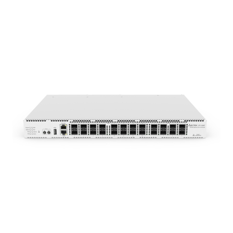
ELTEX LTP-8X Installation manual

LTP-8X
Operation Manual
Version 3.24.1, 26.02.2016

_____________________________________________________________________________
____________________________________________________________________________
2LTP-8X optical line terminal
Table of contents
TABLE OF CONTENTS .....................................................................................................................................................2
REVISION HISTORY ........................................................................................................................................................7
TERMS AND DEFINITIONS..............................................................................................................................................8
PART I GENERAL ......................................................................................................................................................9
CHAPTER 1. INTRODUCTION ............................................................................................................................10
CHAPTER 2. APPLICATION ................................................................................................................................11
CHAPTER 3. DELIVERY PACKAGE ......................................................................................................................12
CHAPTER 4. SPECIFICATIONS............................................................................................................................13
CHAPTER 5. COMPATIBLE SFP TRANSCEIVERS .................................................................................................15
CHAPTER 6. DESIGN..........................................................................................................................................16
6. 1 Front Panel.................................................................................................................................................16
6. 2 Rear Panel ..................................................................................................................................................17
6. 3 Light Indication ..........................................................................................................................................18
6. 4 Temperature Sensors.................................................................................................................................19
6. 5 Ventilation System .....................................................................................................................................19
CHAPTER 7. SAFETY PRECAUTIONS AND INSTALLATION PROCEDURE.............................................................20
Introduction............................................................................................................................................................20
7.1 Safety requirements ................................................................................................................................20
7.2 Terminal Installation Procedure ..............................................................................................................21
PART II GETTING STARTED WITH THE TERMINAL ......................................................................................................24
CHAPTER 8. CONNECTING TO TERMINAL CLI ...................................................................................................25
Introduction............................................................................................................................................................25
8.1 CLI Views Hierarchy....................................................................................................................................25
8.2 Connecting to CLI with Telnet Protocol .....................................................................................................26
8.3 Connecting to CLI with Secure Shell Protocol ............................................................................................27
CHAPTER 9. GETTING STARTED WITH TERMINAL CLI.......................................................................................29
Introduction............................................................................................................................................................29
9.1 CLI Views Hierarchy....................................................................................................................................29
9.2 CLI Automatic Code Completion ................................................................................................................30
9.3 CLI Command History.................................................................................................................................30
9.4 Group operations.......................................................................................................................................31
PART III CONFIGURING THE TERMINAL ..............................................................................................................32
CHAPTER 10. NETWORK SETTINGS ..................................................................................................................33
Introduction............................................................................................................................................................33

___________________________________________________________________________
_______________________________________________________________________________
LTP-8X optical line terminal 3
10.1 Adjustments of network settings ..........................................................................................................33
10.2 AAA Configuration.................................................................................................................................34
CHAPTER 11. TERMINAL CONFIGURATION...................................................................................................... 35
Introduction............................................................................................................................................................35
11.1 Configuration Structure ........................................................................................................................35
11.2 Configuration Lifecycle.......................................................................................................................... 36
11.3 Configuration Autosave ........................................................................................................................ 36
11.4 Creating Configuration Backup .............................................................................................................37
11.5 Configuration Restore ...........................................................................................................................38
11.6 Configuration Reset...............................................................................................................................38
CHAPTER 12. USER MANAGEMENT .................................................................................................................39
Introduction............................................................................................................................................................39
12.1 User List Preview...................................................................................................................................40
12.2 Adding a New User................................................................................................................................40
12.3 Changing User Password ....................................................................................................................... 41
12.4 Viewing and Changing User Access Rights ............................................................................................ 41
12.5 Deleting a User......................................................................................................................................41
CHAPTER 13. SERVICES CONFIGURATION........................................................................................................42
Introduction............................................................................................................................................................42
13.1 SNMPD Configuration ...........................................................................................................................42
13.2 NTPD Configuration...............................................................................................................................43
13.3 ACSD and DHCPD Configuration ...........................................................................................................45
13.3.1 ACSD configuration ............................................................................................................................45
13.3.2 DHCPD configuration ........................................................................................................................ 45
13.4 LOGD Configuration .............................................................................................................................. 46
Introduction ....................................................................................................................................................... 46
13.4.1 Modules Configuration..................................................................................................................... 48
13.4.2 Configuring SYSLOG parameters ......................................................................................................48
13.5 ALARMD Configuration ......................................................................................................................... 49
Introduction ....................................................................................................................................................... 49
13.5.1 Active Alarms Log Configuration ...................................................................................................... 50
CHAPTER 14. VLAN CONFIGURATION .............................................................................................................. 52
Introduction............................................................................................................................................................52
14.1 Adding a VLAN.......................................................................................................................................52
14.2 VLAN Configuration............................................................................................................................... 53
14.3 IGMP Proxy Configuration.....................................................................................................................54
14.4 Deleting a VLAN ..............................................................................................................................................54
14.5 Terminal VLANs ..............................................................................................................................................54
CHAPTER 15. INTERFACES CONFIGURATION ...................................................................................................56
Introduction............................................................................................................................................................56

_____________________________________________________________________________
____________________________________________________________________________
4LTP-8X optical line terminal
15.1 Ethernet Interfaces Configuration ........................................................................................................57
15.2 GPON Interfaces Configuration.............................................................................................................59
CHAPTER 16. LAG CONFIGURATION ......................................................................................................................60
Introduction............................................................................................................................................................60
16.1 LAG Configuration .................................................................................................................................61
CHAPTER 17. DHCP RELAY AGENT CONFIGURATION.......................................................................................64
Introduction............................................................................................................................................................64
17.1 DHCP Relay Agent Profiles Management..............................................................................................65
17.2 DHCP Relay Agent Profiles Configuration .............................................................................................66
CHAPTER 18. PPPOE INTERMEDIATE AGENT CONFIGURATION ......................................................................67
Introduction............................................................................................................................................................67
18.1 PPPoE Intermediate Agent Profiles Configuration ................................................................................68
PART IV ONT CONFIGURATION...........................................................................................................................69
CHAPTER 19. SERVICE MODELS .......................................................................................................................70
Introduction............................................................................................................................................................70
"VLAN for Subscriber" Architecture........................................................................................................................70
"VLAN for Service" Architecture .............................................................................................................................71
19.1 Operating Principle ...............................................................................................................................72
19.2 Model 1 .................................................................................................................................................72
19.3 Model 2 .................................................................................................................................................74
19.4 Model 3 .................................................................................................................................................75
19.5 Model Configuration .............................................................................................................................76
CHAPTER 20. ONT CONFIGURATION................................................................................................................77
Introduction............................................................................................................................................................77
20.1 General Configuration Principles ..........................................................................................................77
20.2 ONT Profiles Configuration ...................................................................................................................78
20.2.1. Cross-Connect Profile Configuration ................................................................................................78
20.2.2. DBA Profile Configurationn ..............................................................................................................79
20.2.3. Shaper Profile Configuration ............................................................................................................79
20.2.4. Ports Profile Configuration ...............................................................................................................79
20.2.5. Management Profile Configuration..................................................................................................80
20.3 ONT Configuration Procedure...............................................................................................................80
20.3.1. Model 1 ............................................................................................................................................81
20.3.2. Model 2 ............................................................................................................................................84
20.3.3. Model 3 ............................................................................................................................................84
CHAPTER 21. DBA CONFIGURATION................................................................................................................88
Introduction............................................................................................................................................................88
21.1 DBA Profiles Assignment .......................................................................................................................90
21.1.1. Services in Different T-CONTs...........................................................................................................90
21.1.2. Services in One T-CONT ....................................................................................................................90

___________________________________________________________________________
_______________________________________________________________________________
LTP-8X optical line terminal 5
21.1.3. One Profile for Multiple ONTs ..........................................................................................................92
21.2 DBA Configuration.................................................................................................................................94
21.2.1. T-CONT Type 1 Configuration...........................................................................................................94
21.2.2. T-CONT Type 2 Configuration...........................................................................................................94
21.2.3. T-CONT Type 3 Configuration...........................................................................................................96
21.2.4. T-CONT Type 4 Configuration...........................................................................................................96
21.2.5. T-CONT Type Configuration..............................................................................................................97
CHAPTER 22. RG ONT.......................................................................................................................................99
Introduction............................................................................................................................................................99
22.1 Services Combined Configuration .......................................................................................................101
CHAPTER 23. HIGH SPEED INTERNET CONFIGURATION ................................................................................104
CHAPTER 24. MULTICAST CONFIGURATION ..................................................................................................105
Introduction..........................................................................................................................................................105
24.1 Model 1 Multicast Configuration ........................................................................................................107
24.2 Model 2 (3) Multicast Configuration...................................................................................................109
CHAPTER 25. VOIP CONFIGURATION.............................................................................................................112
Introduction..........................................................................................................................................................112
25.1 VoIP Configuration in OMCI Management Domain ............................................................................112
25.2 VoIP Configuration in RG Management Domain.................................................................................113
CHAPTER 26. TR-069 PROTOCOL MANAGEMENT CONFIGURATION .............................................................114
Introduction..........................................................................................................................................................114
26.1 Configuration of a TR-069 Inband management channel ...................................................................115
26.2 Configuration of a TR-069 OOB Management Channel ......................................................................116
26.3 TR-069 Client Configuration ................................................................................................................117
CHAPTER 27. ONT CONFIGURATIONS TEMPLATES ........................................................................................119
Introduction..........................................................................................................................................................119
27.1 ONT Configuration Templates.............................................................................................................119
27.2 ONT Configuration Templates Assignment .........................................................................................120
27.3 ONT Configuration Preview with Templates .......................................................................................120
PART V TERMINAL MONITORING ...................................................................................................................122
CHAPTER 28. GENERAL ..................................................................................................................................123
28.1 Information on Terminal Software Current Version ...........................................................................123
28.2 Terminal Information Preview ............................................................................................................123
28.3 Information on Terminal Operating Time ...........................................................................................124
28.4 Network Connection Check.................................................................................................................124
CHAPTER 29. TERMINAL OPERATION LOG.....................................................................................................125
CHAPTER 30. ACTIVE ALARMS LOG................................................................................................................126
CHAPTER 31. GPON MONITORING ................................................................................................................127
31.1 GPON OLT State ..................................................................................................................................127
31.2 GPON Interface State ..........................................................................................................................128

_____________________________________________________________________________
____________________________________________________________________________
6LTP-8X optical line terminal
31.3 MAC Table Preview .............................................................................................................................129
31.4 Statistics for GPON Interfaces .............................................................................................................129
31.5 Statistics for OLT Ethernet Interfaces..................................................................................................130
31.6 Multicast Statistics ..............................................................................................................................130
CHAPTER 32. ONT MONITORING ...................................................................................................................131
32.1 ONT Configurations List.......................................................................................................................131
32.2 Active ONT List ....................................................................................................................................131
32.3 Online ONT List....................................................................................................................................131
32.4 Offline ONT List ...................................................................................................................................132
32.5 ONT Statistics ......................................................................................................................................133
32.6 ONT Bit Error Rate...............................................................................................................................133
PART VI TERMINAL MAINTENANCE ..................................................................................................................134
CHAPTER 33. SFP TRANSCEIVERS REPLACEMENT ..........................................................................................135
CHAPTER 34. VENTILATION UNITS REPLACEMENT ........................................................................................137
CHAPTER 35. OLT FIRMWARE UPDATE..........................................................................................................139
CHAPTER 36. ONT FIRMWARE UPDATE .........................................................................................................140
Introduction..........................................................................................................................................................140
36.1 ONT Firmware Update Download .......................................................................................................140
36.2 ONT Firmware Custom Update ...........................................................................................................140
36.3 ONT Firmware Autoupdate .................................................................................................................141

___________________________________________________________________________
_______________________________________________________________________________
LTP-8X optical line terminal 7
Revision History
Issue 3b, 26 February 2016
—Manual is adjusted in accordance with LTP-8X R3.24.1 command system.
—Added Section 13.3 describing configuration ACS.
—Added Section 14.5 describing configuration terminal vlans.
—Updated chapters 19 and 20 due the models refactoring.
Issue 3a, 21 July 2014
—Manual is adjusted in accordance with LTP-8X R3.20.2 command system.
—Added Section 9.4 on group operations.
—Added Section 27 describing operations with ONT configuration templates.
Issue 1, 21.04.2014
—Added Section 11.1 describing configuration structure.
—Added Section 11.3 describing configuration autosave.
—Added Step 7 in Section 11.1 describing configuration of MAC addresses lifetime.
—Corrected the name of Table 18.1.
—Renamed Section 30.6 to Multicast Statistics View.
—Added Appendix A with Triple Play configuration example for the "VLAN for Subscriber" model.
—Added optical interfaces specification for Ligent Photonics LTE3680M-BC into Table 3.1.
18.04.2014
The first issue of the document.

_____________________________________________________________________________
____________________________________________________________________________
8LTP-8X optical line terminal
Terms and Definitions
CBR
Constant bitrate
DBA
Dynamic bandwidth allocation
FW
Firmware
GPON
Gigabit PON
IGMP
Internet Group Management Protocol
IP
Internet protocol
OLT
Optical Line Terminal
ONT
Optical Network Terminal
ONU
Optical Network Unit
SNTP
Simple Network time protocol
SNMP
Simple Network Manazgement Protocol
SFP
Small Form-factor Pluggable
URI
Uniform Resource Identifier
TFTP
Trivial File Transfer Protocol

___________________________________________________________________________
_______________________________________________________________________________
LTP-8X optical line terminal 9
Part I General

_____________________________________________________________________________
____________________________________________________________________________
10 LTP-8X optical line terminal
Chapter 1.
Introduction
GPON is a network of passive optical networks (PON) type. It is one of the most effective state-of-the-art
solutions for the "last mile" issue that significantly reduces the required amount of cable and provides
information transfer with downstream rate up to 2.5 Gbps and upstream rate up to 1.25 Gbps. Being
used in access networks, GPON-based solutions allow end users to have access to new services based on
IP protocol in addition to more common ones.
The key GPON advantage is the use of one optical line terminal (OLT) for multiple optical network
terminals (ONT). OLT converts Gigabit Ethernet and GPON interfaces and is used to connect a PON
network with data communication networks of a higher level.
The range of OLT GPON equipment produced by Eltex comprises of LTP-8X terminal with internal
Ethernet switch with 8 GPON ports and RSSI function.
The Operation Manual describes application, key specifications, installation, configuration, monitoring,
and software retrofit for the devices.

___________________________________________________________________________
_______________________________________________________________________________
LTP-8X optical line terminal 11
Chapter 2.
Application
LTP-8X optical line terminal is designed to establish connection with upstream equipment and provide
broadband access over passive optical networks. Ethernet connection is established through Gigabit
uplink and 10G Base-X interfaces; GPON interfaces are used to connect to optical networks. Each
interface can provide connection for 64 subscriber optical terminals through one fibre and supports
dynamic bandwidth allocation (DBA).
The following services are provided to end users:
—voice communications;
—HDTV;
—VoIP telephony (based on SIP/H.323/MGCP protocols);
—high-speed Internet access;
—IP TV;
—video-on-demand (VoD);
—video conferencing; and
—online educational and entertainment programs.
The device has the following functions:
—dynamic bandwidth allocation (DBA);
—support of quality assurance mechanisms (QoS), GPON ports prioritization for different types of
traffic according to 802.1p;
—security functions;
—ONT remote control, automatic detection of new ONT;
—FEC errors correction;
—power measurement support for signals received from each ONT (RSSI) 1
—VLAN organisation (VLAN ID range: 0-4094);
—MAC address filtering, 16,000 records in the MAC addresses table;
—support of IGMP snooping v1/2/3, IGMP proxy;
—support of DHCP snooping, DHCP relay agent; and
—support of PPPoE IA.

_____________________________________________________________________________
____________________________________________________________________________
12 LTP-8X optical line terminal
Chapter 3.
Delivery Package
The standard delivery package includes:
1. LTP-8X optical line terminal.
2. A mounting set for 19'' rack.
3. RS-232 DB9(F)–DB9(F) console cable.
4. A CD with Operation Manual and Quick Setting Guide.
5. Declaration of Conformity.
6. Device Certificate.

___________________________________________________________________________
_______________________________________________________________________________
LTP-8X optical line terminal 13
Chapter 4.
Specifications
Table 4.1 Key Specifications of Optical Line Terminal1
Interfaces
Ethernet interfaces, pcs.
10
Connector
RJ-45
SFP
Data rate, Mbit/sec
10/100/1000
duplex/half-duplex
1000/10000
duplex
Standards
10/100 Base-TX/
1000 Base-T
1000 Base-X, 10GBase-X
GPON Interfaces, pcs.
8
Connector type
SC/UPC (socket) complies with ITU-T G.984.2, FSAN Class B+, SFF-
84721
Transmission medium
fibre optical cable SMF-9/125, G.652
Standards
Digital RSSI1
Splitting ratio
1:4, 1:8, 1:16, 1:32, 1:641
Transmitter
1490 nm DFB Laser1
Data Rate
2488 Mb/s1
Average Launch Power
1.5..+5 dBm1
Spectral Line Width -20 dB
1.0 nm1
Receiver
1310 nm APD/TIA Detector/Amplifier1
Data Rate
1244 Mb/s1
Receiver Sensitivity
-28 dBm1
Receiver Optical Overload
-8 dBm1
Processor
Processor type
Marvell Sheeva, ARMV5TE architecture
Clock frequency
800 MHz
Number of cores
1
1Optical parameters for Ligent Photonics LTE3680M-BC

_____________________________________________________________________________
____________________________________________________________________________
14 LTP-8X optical line terminal
Operating memory
256 MB 320 MHz
Non-volatile memory
2x32 Mb SPI Flash
Switch
Ethernet switch
Marvell Packet Processor
Performance
128 Gbps
Table of MAC addresses
16,000 records
VLAN support
up to 4,000 according to 802.1Q
Quality of Services (QoS)
8 prioritized output queues for each port
Control
Local control
Command line interfaces (CLI)
Remote control
CLI (SSH2, Telnet), SNMP
Monitoring
CLI, SNMP
Access restriction
Password, IP address
General parameters
Power voltage
AC: 150–250 V, 50 Hz; DC: -36...-72 V
Power consumption
not more than 20 W
Operating temperature
range
from +5 to +40 °C
Relative humidity
up to 80 %
Dimensions
with power supply module: 430×44×258 mm,
19" form-factor, 1U size
Weight
not more than 2.5 kg

___________________________________________________________________________
_______________________________________________________________________________
LTP-8X optical line terminal 15
Chapter 5.
Compatible SFP transceivers
Correct and error-free operation of GPON interface requires exact parameters to be chosen and set for
each transceiver type. This can be done only under laboratory conditions by the terminal vendor. Table
6.1 lists SFP transceivers for which seamless terminal operation is guaranteed.
DDMI (Digital Diagnostic Monitoring Interface) provides information about transceiver parameters such
as temperature, power voltage, etc. DDMI also measures the level of ONT signal (RSSI). All compatible
transceivers support this function.
Table 6.1. The List of Compatible SFP Transceivers
Vendor
SFP transceiver model
Class
DDMI
NEOPHOTONICS
PTB38J0-6538E-SC
B+
+
NEOPHOTONICS
38J0-6537E-STH1+
C+ HP
+
NEOPHOTONICS
38J0-6537E-STH2+
C+ HP
+
NEOPHOTONICS
38J0-6537E-STH3+
C+ HP
+
Ligent Photonics
LTE3680M-BC
B+
+
Ligent Photonics
LTE3680M-BH
B+
+
Ligent Photonics
LTE3680P-BC
C+
+
Ligent Photonics
LTE3680P-BH
C+
+
Ligent Photonics
LTE3680P-BC2
C+ HP
+

_____________________________________________________________________________
____________________________________________________________________________
16 LTP-8X optical line terminal
Chapter 6.
Design
6. 1 Front Panel
The device has a metal case available for 19 form-factor rack-mount 1U shelf installation. The front
panel of the terminal is shown in Fig. 6.1.
Table 4.1 lists sizes, LEDs, and controls located on the front panel.
Fig. 6.1. Front Panel of Terminal
Table 4.1. Description of Connectors, LEDs, and Controls Located on the Front Panel
Component
Description
Console
RS-232 port for local control of the terminal
GE Port 0..3
4 RJ-45 connectors of 10/100/1000 Base-T Gigabit uplink interface to connect to IP
network
Combo GE 4..7
4 chassis for SFP modules of 1000 Base-X uplink interface to connect to IP network
4 RJ-45 connectors of 10/100/1000 Base-T Gigabit uplink interface to connect to IP
network
10G/1G 0..1
2 chassis for SFP modules of 1000 Base-X uplink interface to connect to IP network
GPON
8 chassis for GPON SFP modules
Power
Power indicator of the terminal
Status
Operating indicator of the terminal

___________________________________________________________________________
_______________________________________________________________________________
LTP-8X optical line terminal 17
F
A functional key that reboots the terminal and resets it to factory settings:
- pressing the key for less than 10 seconds reboots the terminal;
- pressing the key for more than 10 seconds resets the terminal to factory settings.
4 electrical Ethernet and 4 optical interfaces are combined (Combo GE 4..7). The combined
ports may have only one active interface at the same time.
6. 2 Rear Panel
The rear panel of the terminal is shown in Fig. 6.2 and 6.3.
Table 4.2 lists rear panel connectors.
Fig. 6.2. Rear Panel of Optical Line Terminal (DC)
Fig. 6.3. Rear Panel of Optical Line Terminal (AC)

_____________________________________________________________________________
____________________________________________________________________________
18 LTP-8X optical line terminal
Table 6.2. Description of Connectors, LEDs, and Controls Located on the Rear Panel
Component
Description
36 .. 72 VDC, max 5A
Connector for DC power supply
150-250 V AC, 50 Hz, max 1 A
Connector for AC power supply
Fan0, Fan1
Ventilation units
Earth bonding point
Earth bonding point of the terminal
6. 3 Light Indication
The Status and Power LEDs located on the front panel indicate the current status of the terminal. Table
4.3 lists possible statuses of the LEDs.
Table 6.3. Light Indication of Terminal Status
LED
LED Status
Terminal Status
Status
Flashes green
Normal operation
Flashes red
Critical failure
Power
Glows green
Power supply on terminal is on

___________________________________________________________________________
_______________________________________________________________________________
LTP-8X optical line terminal 19
6. 4 Temperature Sensors
2 temperature sensors are used to measure temperature inside the terminal case. Fig. 6.4 shows the
sensor location on the PCB.
Temperature sensor 2
Temperature sensor 1
Fig. 6.4. Temperature Sensors Arrangement
6. 5 Ventilation System
The rear, front, and side panels of the terminal have ventilation grids for heat removal. The rear panel
has four ventilation units installed (Fig. 6.2 and 6.3).
Air flows in through the perforated front and side panels, circulates through all internal components,
cools them down, and then is removed with the help of ventilators located on the perforated rear panel.
The device incorporates 2 ventilators. The ventilation units are detachable. Procedure for
dismantlement and installation is described in Chapter 33.

_____________________________________________________________________________
____________________________________________________________________________
20 LTP-8X optical line terminal
Chapter 7.
Safety precautions and installation procedure
Introduction
This chapter describes installation of the terminal into a rack and connection to a power supply.
7.1 Safety requirements
General
Any operations with the terminal should comply with Safety Rules for Operation of Customers' Electrical
Installations.
Operations with the terminal should be carried out only by personnel authorised in
accordance with the safety requirements.
1. Before operating the terminal, all engineers should undergo special training.
2. The terminal should be connected only to properly functioning equipment.
3. The terminal is to be operated 24/7 provided the following requirements are met:
a. ambient temperature from +5 to +40 °C;
b. relative humidity up to 80 % at +25 °C;
c. atmosphere pressure from 6.0×10⁴to 10.7×10⁴Pa (from 450 to 800 mm Hg).
4. The terminal should not be exposed to mechanical shock, vibration, smoke, dust, water, and
chemicals.
5. In order to avoid components overheating which may result in terminal malfunction, do not
block air vents or place objects on the terminal.
6. Prior to connecting the terminal to a power source, ensure that the terminal case is grounded
with an earth bonding point. The earthing wire should be securely connected to the earth bonding
point. The resistance between the earth bonding point and earthing busbar should be less than 0.1
Ohm.
7. PC and measurement instruments should be grounded prior to connection to the terminal. The
potential difference between the terminal case and the cases of the instruments should be less than 1 V.
8. Prior to turning the terminal on, ensure that all cables are undamaged and securely connected.
Other manuals for LTP-8X
3
Table of contents
Other ELTEX Touch Terminal manuals

ELTEX
ELTEX ONT NTU-1 User manual

ELTEX
ELTEX LTP-8X User manual

ELTEX
ELTEX TAU-32M.IP User manual

ELTEX
ELTEX NTU-52V User manual

ELTEX
ELTEX NTU-2V User manual

ELTEX
ELTEX LTP-8X User manual

ELTEX
ELTEX TAU-36.IP User manual

ELTEX
ELTEX LTP-16N Instruction sheet

ELTEX
ELTEX NTU-RG-5402G-W User manual

ELTEX
ELTEX TAU-36.IP User manual