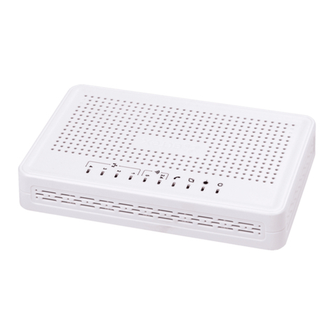
ELTEX NTU-MD500P User manual

Subscriber terminal
NTU-MD500P
User Manual
Firmware version2.4.7

NTU-MD500P.User Manual
2
Contents
1 List of changes..................................................................................................................................4
2 Introduction .......................................................................................................................................5
3 Product Description ..........................................................................................................................6
3.1 Purpose ......................................................................................................................................... 6
3.2 Overview ........................................................................................................................................ 6
3.3 Technical specifications............................................................................................................... 7
3.4 Design............................................................................................................................................ 9
3.4.1 Front panel layout ......................................................................................................................9
3.4.2 Side and back panels of the device ........................................................................................10
3.5 Light indication............................................................................................................................ 11
3.6 Delivery package......................................................................................................................... 11
4 Installing and connecting NTU-MD500P .......................................................................................12
4.1 Operating conditions and installation procedure...................................................................... 12
4.1.1 Safety requirements ................................................................................................................12
4.1.2 Installation procedure..............................................................................................................12
4.2 Connecting the device ................................................................................................................ 14
5 Device architecture .........................................................................................................................15
6 Configuring the device via web interface. Admin access. ...........................................................16
6.1 Status menu. Device information .............................................................................................. 18
6.1.1 Device submenu. General information on the device............................................................18
6.1.2 IPv6 Status submenu. IPv6 System Information ...................................................................19
6.1.3 PON submenu. Optical module status ...................................................................................20
6.1.4 LAN submenu. Information on the status of LAN interface..................................................21
6.2 LAN menu. Configuring LAN interface ...................................................................................... 21
6.3 WAN menu. Configuring WAN interface.................................................................................... 22
6.3.1 PON WAN submenu.................................................................................................................22
6.3.2 VPN submenu ..........................................................................................................................23
6.4 Services menu. Configuring services ........................................................................................ 26
6.4.1 DHCP Settings submenu. Configuring DHCP ........................................................................26
6.4.2 DNS submenu ..........................................................................................................................27
6.4.3 Firewall submenu. Configuring the firewall............................................................................28
6.4.4 UPnP submenu. Automatic configuration of network devices.............................................33
6.4.5 RIP submenu. Configuring dynamic routing ..........................................................................34
6.5 Advance menu. Advanced settings ........................................................................................... 35
6.5.1 ARP Table submenu. Viewing the ARP protocol cache ........................................................35
NTU-MD500P.User Manual
3
6.5.2 Bridging submenu. Configuring Bridging parameters ...........................................................35
6.5.3 Routing submenu. Configuring routing ..................................................................................36
6.5.4 Interface grouping submenu. Combining interfaces into groups.........................................37
6.5.5 IP QoS submenu. Configuring the quality of services provided (QoS).................................37
6.5.6 PoE Settings submenu. Configuring PoE ports .....................................................................41
6.5.7 Link mode submenu. Configuring LAN ports.........................................................................42
6.5.8 Others submenu. Additional settings .....................................................................................42
6.5.9 IPv6 submenu. Configuring IPv6 protocol..............................................................................43
6.6 Diagnostics menu ....................................................................................................................... 50
6.6.1 Ping submenu. Checking the availability of network devices...............................................50
6.6.2 Traceroute submenu. Network diagnostics...........................................................................50
6.6.3 System Log submenu. Logging system events .....................................................................50
6.7 Admin menu ................................................................................................................................ 51
6.7.1 Settings submenu. Restore and reset settings......................................................................51
6.7.2 GPON Setting submenu. Configuring access to GPON.........................................................52
6.7.3 Commit/Reboot submenu. Saving changes and restarting the device................................53
6.7.4 Logout submenu. Log out the account ..................................................................................53
6.7.5 Password submenu. Setting up access control (setting passwords)..................................54
6.7.6 Firmware upgrade submenu. Software Update .....................................................................54
6.7.7 Remote Access submenu. Configuring remote access rules...............................................55
6.7.8 Time zone submenu. Configuring system time.....................................................................55
6.7.9 TR-069 submenu. Configuring TR-069 ...................................................................................56
6.8 Statistics menu. Information about the traffic on the device ports......................................... 57
6.8.1 Interface submenu. Information about counters and errors.................................................57
6.8.2 PON submenu ..........................................................................................................................57

NTU-MD500P.User Manual
4
1 List of changes
Document version Software Release date Changes
Version 1.1 2.4.7 09.2022 Second publication
Version 1.0 1.0.1 04.2021 First publication

NTU-MD500P.User Manual
5
2 Introduction
GPON network belongs to one of the varieties of passive optical PON networks. This is one of the most
modern and effective solutions for "last mile", which allows significant savings on cable infrastructure and
provides data transmission speed of up to 2.5 Gbps downlink and 1.25 Gbps uplink. The use of GPON-based
solutions in access networks makes it possible to provide end users with new IP services together with
traditional ones.
The main advantage of GPON is the use of a single line terminal (OLT) for multiple subscriber devices (ONT).
OLT is a converter of Gigabit Ethernet and GPON interfaces, which serves to connect the PON network with
higher-level data transmission networks. The ONT device is designed to connect customers' equipment to
broadband access services. It can be used in residential areas and business centers.
The user manual describes the purpose, main technical specifications, configuration rules and monitoring of
the optical network terminal NTU-MD500P.
Notes and Warnings
The tips contain important information or recommendations for using and configuring the device.
The notes contain additional information on using and configuring the device.
Warnings inform of the situations when actions may harm the device or a user, lead to fault operation
of the device or data loss.

NTU-MD500P.User Manual
6
•
•
•
•
•
•
•
•
•
•
•
•
•
•
•
•
•
•
•
•
•
•
•
•
•
•
•
•
•
•
•
•
•
3 Product Description
3.1 Purpose
NTU-MD500P is an optical network terminal that has four 10/100/1000BASE-T ports with support for IEEE
802.3at PoE+ technology. NTU-MD500P provides up to 30 W of power on 10/100/1000BASE-T ports with a
PoE power budget of 65 W.
Support for PoE technology allows NTU-MD500P to supply power via UTP cable to IP phones, wireless access
points, IP cameras and other PoE-enabled devices.
The advantage of GPON technology is the optimum use of bandwidth. This technology is the next step to
provide new high-speed internet connection at home and in offices. Designed to deploy a network inside a
home or building, NTU-MD500P provides reliable connection with high bandwidth over long distances for users
living and working in remote apartment buildings and business centers.
3.2 Overview
NTU-MD500P has the following interfaces:
1 PON SC/APC port for connecting to the operator's network (WAN);
4 Ethernet RJ-45 LAN ports (10/100/1000BASE-T) for connecting network devices (LAN).
NTU-MD500Psupports the following functions:
PoE management and monitoring via OMCI:
ONU-G::PSE overload yellow;
ONU-G::PSE overload red;
Physical path termination point Ethernet UNI::Power control;
Power over Ethernet control::Operational state;
Power over Ethernet control::Power detection status;
Power over Ethernet control::Power classification status;
Power over Ethernet control::Current Power Consumption;
Power over Ethernet control::AVC;
Power over Ethernet control::Power priority.
Network functions:
support for TR-069;
operation in "bridge" or "router" mode;
PPPoE (auto, PAP-, CHAP-, MSCHAP-authorization);
IPoE (DHCP client and static);
DNS (Domain Name System);
DynDNS (Dynamic DNS);
UPnP (Universal Plug and Play);
VPN in L2TP mode;
L2TP over IPsec;
IPsec (trasport mode);
NAT (Network Address Translation);
NTP (Network Time Protocol);
QoS (quality of service mechanisms);
IGMP-snooping;
IGMP proxy;
VLAN according to IEEE 802.1Q.
Firmware update via TR-069, OMCI, HTTP, TFTP;
Remote monitoring and configuration:
SNMP-agent OLT;
CLI OLT.

NTU-MD500P.User Manual
7
The figure below shows the use case of NTU-MD500P.
Figure 1 — NTU-MD500P use case
3.3 Technical specifications
The main technical parameters of the terminal are given in Table 1:
Table 1 — Technical specifications
Parameters of LAN Ethernet interfaces
Number of interfaces 4
Electrical connector RJ-45
Data rate Auto-detection, 10/100/1000 Mbps, duplex/half duplex
Supported standards IEEE 802.3i 10BASE-T Ethernet
IEEE 802.3u 100BASE-TX Fast Ethernet
IEEE 802.3ab 1000BASE-T Gigabit Ethernet
IEEE 802.3x Flow Control
IEEE 802.3 NWay auto-negotiation
IEEE 802.3af
IEEE 802.3at
PON interface parameters
Number of interfaces 1
Supported standards ITU-T G.984.x Gigabit-capable passive optical networks (GPON)
ITU-T G.988 ONU management and control interface (OMCI)
specification
IEEE 802.1Q Tagged VLAN
IEEE 802.1P Priority Queues
IEEE 802.1D Spanning Tree Protocol
Connector type SC/APC
corresponds to ITU-T G.984.2, ITU-T G.984.5 Filter, FSAN Class B+,
SFF-8472
Transmission medium Fiber optic cable SMF — 9/125, G.652
Split ratio Up to 1:128

NTU-MD500P.User Manual
8
•
•
•
•
•
Maximum distance 20 km
Transmitter: 1310 nm
Upstream data rate 1244 Mbps
Transmitter power From +0.5 dBm to +5 dBm
Spectrum width (RMS) 1 nm
Receiver: 1490 nm
Downstream data rate 2488 Mbps
Receiver sensitivity From -8 to -28, BER≤1.0x10⁻¹⁰
Optical overload of the receiver -8 dBm
Management
Local management Web, CLI
Remote control TR-069, OMCI
Firmware update OMCI, TR-069, HTTP, TFTP
Access restriction By password
General parameters
Power supply 110-250 V AC, 50-60 Hz
Maximum power consumption 80 W
Operating temperature range From 0 to +40 °C
Relative humidity No more than 80%
Dimensions (W × H × D) 267 × 44 × 178 mm
Form factor 19", size 1U
Weight 1.56 kg

NTU-MD500P.User Manual
9
3.4 Design
This section describes design and indicators layout of the device. Images of the front, back and side panels of
the device are shown in the section, connectors, LED indicators and controls are described.
NTU-MD500P is enclosed in a metal case suitable for 19” rack, the height of the case is 1U.
3.4.1 Front panel layout
The device front panel layout is shown inFigure 2.
Figure 2 — NTU-MD500P front panel
Table 2 — Description of connectors and front panel controls
№Front panel element Description
1 Power Device power indicator
Status Device operation indicator
Alarm Indicator of optical signal absence
Link Indicator of optical interface operation
PoE 1-4 Status indicators of PoE ports
2 F Functional button to restart the device and reset to factory settings:
- pressing the button for less than 10 seconds restarts the device;
- pressing the button for more than 10 seconds resets the device to the factory
settings.
3 LAN 10/100/1000 1..4 4 RJ-45 ports for connecting network devices
4 PON PON SC port (socket) of the GPON optical interface
5 110-250 V AC 50-60 Hz Connector for AC power source

NTU-MD500P.User Manual
10
3.4.2 Side and back panels of the device
Figure 3 — NTU-MD500P back panel
№Back panel element
1 Earth bonding point
Figure 4 — NTU-MD500P left-side panel
There are ventilation grilles on the side and back panels of the device, which serve to remove heat. Do not
cover the ventilation grilles, it can lead to overheating of the device components and cause malfunctioning.
See recommendations for device installation in the Installing and connecting NTU-MD500Psection.

NTU-MD500P.User Manual
11
•
•
•
•
3.5 Light indication
System indicators (Power, Status, Alarm, Link) are used to determine the operation status of the device nodes.
Table 3 — Light indication of device status
Indicator
name
Indicator status Device status
Power Solid green The power is on, the device is operating normally
Off The power is off
Status Solid red The moment the drivers are lauching
Solid green The device has a configuration which differs from the default one
Green, flashing
slowly
The default configuration is set on the device
PoE 1-4 Solid green The PoE consumer is connected, the power supply is in on (the indicator
corresponds to a port).
Solid red PoE error on port
Off PoE consumer is not connected
Alarm Off Normal operation of the device
Solid red There is no optical signal
Link Off The device is loading
Green,
flashingfast
Getting settings via OMCI
Solid green The device has been successfully configured via OMCI.
Green, flashing
slowly
Configuration is absent (authorization)
Red,flashing
slowly
No signal from OLT
LAN P1..P4 Green 10/100 Mbps connection has been established
Orange 1000 Mbps connection has been established
Flashing The process of packet data transmission
3.6 Delivery package
The basic delivery package of NTU-MD500P device includes:
Subscriber terminal NTU-MD500P;
Power cord with euro plug C-13, 1.8 m;
Mounting kit for installing into 19" rack;
Technical passport.

NTU-MD500P.User Manual
12
1.
2.
3.
•
•
•
4.
5.
1.
2.
3.
•
•
•
4 Installing and connecting NTU-MD500P
4.1 Operating conditions and installation procedure
This chapter describes procedure of installation into 19'' rack and connection to a power supply.
4.1.1 Safety requirements
General requirements
When working with the device, it is necessary to comply with safety regulations for the operation with electrical
installations.
The operation of the device must be carried out by engineering and technical personnel who have
received special training.
Connect only fault-free auxiliary equipment to the terminal.
The terminal is designed for twenty-four-hour operation under the following conditions:
ambient temperature from 0 to +40 °C;
relative humidity up to 80 % at 25 °C;
atmospheric pressure from 6.0×10⁴Pa to 10.7×10⁴Pa (from 450 to 800 mm Hg).
Do not expose the device to mechanical shocks and vibrations, as well as smoke, dust, water, chemicals.
In order to avoid overheating of the device components and disruption of its operation, it is forbidden to
cover the ventilation grilles and place objects on the surface of the device.
Electrical safety requirements
Before connecting the terminal to a power source, it is necessary to ground the device case using the
earth bonding point (Figure 3). A grounding wire must be securely fixed to the earth bonding point. The
resistance value between the earth bonding point and ground bus must not exceed 0.1 Ohm. Before
connecting measuring instruments and a PC to the device, they must be previously grounded. The
potential difference between the device case and measuring instruments should not exceed 1 V.
Before turning on the device, make sure that the cables are intact and securely attached to the
connectors.
When installing or removing the case, make sure that the power supply of the device is switched off.
4.1.2 Installation procedure
Before installing and switching on, it is necessary to check the device for visible mechanical damage. In case
of damage, stop installing the device, draw up an appropriate report and contact the supplier. If the device has
been exposed to low temperature for a long period of time, it should be kept at room temperature for two
hours before operation. After a long stay of the device in high humidity conditions, it is necessary to keep it
under normal conditions for at least 12 hours before switching on.
Mounting
The terminal package includes brackets for installation in a rack and screws for fixing brackets to the device
case. To install the brackets:
Step 1. Align the four screw holes on the bracket with the same holes on the side panel of the device.
Step 2. Using a screwdriver, attach the bracket with screws to the case.
Step 3. Repeat steps 1 and 2 for the second bracket.
It is forbidden to work with the device to persons who are not allowed to operation in accordance with
the safety requirements.

NTU-MD500P.User Manual
13
•
•
•
Figure 5 — Mounting brackets
Installing into a rack
To install the device in a rack:
Step 1. Attach the device to the vertical rails of the rack.
Step 2. Align the holes of the brackets with the holes on the rack rails. Use the holes in the rails at the
same level on both sides of the rack so that the device will be positioned strictly horizontally.
Step 3. Use a screwdriver to attach the device to the rack with screws.
Figure 6 — Mounting brackets
The device has horizontal ventilation. Ventilation grilles are located on the side panels of the device. Do not
cover the ventilation grilles to avoid overheating of the device components and malfunctioning.
To avoid overheating and provide the necessary ventilation, the device must be placed so that there is
at least 10 cm of free space above and below it.

NTU-MD500P.User Manual
14
4.2 Connecting the device
1. Connect LAN port of NTU-MD500P and Ethernet port of your PC using an Ethernet cable.
Figure 7 — Connecting the device to the computer
2. Connect the optical cable provided by the Internet service provider to the PON connector of the device.
Figure 8 — Connecting the device to an Internet service provider's network
3. Connect the terminal to 220 V power supply network using the power adapter included into the delivery
package. Wait until the device is fully loaded.
Figure 9 — Connecting the device to the power supply

NTU-MD500P.User Manual
15
•
•
•
•
•
5 Device architecture
Figure 10 — Logical architecture of the device with the factory configuration
The main elements of the device:
Optical transceiver (SFF module) is designed to convert an optical signal into an electrical one;
Processor (PON chip) — is a converter of Ethernet and GPON interfaces.
In the factory configuration, the following logic blocks are present (Figure 10):
Br0;
eth0…3;
IPInterface1.
The br0 block in this case is intended for combining LAN ports into one group.
The eth0..3 blocksare physically Ethernet ports with an RJ-45 connector for connecting a PC, STB or other
network devices. Logically included in the br0 block.
The Filter and Marking blocks are designed to put local interfaces in one group (in the br0 block). These
blocks are responsible for the traffic transmission rules, the Filter blocks are responsible for incoming traffic
on the interface, the Marking blocks are responsible for outgoing traffic.
The ipinterface1 block is a logical object where IP address for access to the local network is stored, as well as
a DHCP server that distributes addresses to clients.

NTU-MD500P.User Manual
16
1.
2.
3.
4.
6 Configuring the device via web interface. Admin access.
Getting started
To configure the device, you need to connect the device via a web browser:
Open a web browser (web page viewer), for example, Firefox, Google Chrome.
Type the device IP address in the browser's address bar
If the connection is successful, a page with the authorization request will be displayed in the browser
window:
Enter username and password
Click the "Login" button. The starting page of the device's web interface will be displayed in the browser
window.
Changing the password
In order to avoid unauthorized access, it is recommended to change the password for further operation. To
change the password in the menu Admin, section "Password", in the field "Old Password" enter the current
password in the fields "New Password" and "Confirm new password" enter a new password. To save changes,
click the Apply Changes button.
The default IP address: 192.168.0.1, subnet mask: 255.255.255.0
Default user name—admin, password—password.

NTU-MD500P.User Manual
17
1.
2.
3.
Elements of the web interface
General view of the device configuration window is shown below.
The user interface can be divided into 3 parts :
The navigation tree of the device settings menu.
The main window of selected section settings.
Change user button.

NTU-MD500P.User Manual
18
•
•
•
•
•
•
•
•
•
•
•
•
•
•
•
•
•
•
6.1 Status menu. Device information
6.1.1 Device submenu. General information on the device
The section displays general information on the device, the main parameters of LAN and WAN interfaces.
Status →Device
System
Board Type —hardware model;
Serial Number — serial number of the device;
PON Serial —serial number of the device in PON network;
Base WAN MAC —WAN MAC address of the device;
Hardware Version —hardware version of the device;
Uptime —device operation time;
Date/Time —the current time on the device;
Image 1 Firmware Version (Active) —current firmware version;
Image 2 Firmware Version — backup software version;
CPU Usage — percentage of CPU usage;
Memory Usage — percentage ofmemory usage;
Name Servers — name of DNS server;
IPv4 Default Gateway;
IPv6 Default Gateway.
LAN Configuration
IP Address — IP address of the device;
Subnet Mask — network mask of the device;
DHCP Server — status of DHCP server;
MAC Address — MAC address of the device.

NTU-MD500P.User Manual
19
•
•
•
•
•
•
•
•
•
•
•
•
•
•
•
•
•
•
•
•
•
•
•
•
WAN Configuration
Interface —interface name;
VLAN ID —VLAN ID of the interface;
MAC —MAC address of the interface;
Connection Type;
Protocol — the protocol used;
IP Address — IP address of the interface;
Subnet Mask;
Gateway;
NAPT — NAPT state;
Firewall — firewall status;
IGMP Proxy — IGMP Proxy status;
802.1p — 802.1p mark;
Status —interface status.
L2TP Configuration
Interface — interface name;
Protocol — the protocol used;
Local IP Address — the IP address of the L2TP interface;
Remote IP Address — server IP address;
Status — interface status.
To update the data on the page, clickRefresh.
6.1.2 IPv6 Status submenu. IPv6 System Information
The section displays the current status of the IPv6 system.
Status →IPv6
LAN Configuration
IPv6 Address;
IPv6 Link-Local Address — local IPv6 address.
Prefix Delegation
Prefix — prefix ofIPv6address.
WAN Configuration
Interface —interface name;
VLAN ID —VLAN ID of the interface;
Connection Type;

NTU-MD500P.User Manual
20
•
•
•
•
•
•
•
•
•
•
•
•
•
Protocol — the protocol used;
IP Address — IP addressof theinterface;
Status —interface status.
To update the data on the page,clickRefresh.
6.1.3 PON submenu. Optical module status
The section shows the current state of the PON interface.
Status →PON
PON Status
Vendor Name—PON chipset vendor's name;
Part Number— part number of PON chipset;
Temperature —current temperature;
Voltage;
Tx Power —transmission power;
Rx Power —signal power at reception;
Bias Current.
GPON Status
ONU State — a status of authorization on OLT (O1 -> O2 -> O3 -> O4 -> O5 );
ONU ID — device ID on OLT;
LOID Status —authorization status on OLT (Initial -> Standby -> Serial Number -> Ranging - Operation).
To update the data on the page,clickRefresh.
Table of contents
Other ELTEX Touch Terminal manuals

ELTEX
ELTEX LTP-8X User manual

ELTEX
ELTEX NTU-RG-1421G-Wac User manual

ELTEX
ELTEX NTU-2V User manual

ELTEX
ELTEX ONT NTU-1 User manual

ELTEX
ELTEX LTP-8X Installation manual

ELTEX
ELTEX LTP-16N Instruction sheet

ELTEX
ELTEX TAU-36.IP User manual

ELTEX
ELTEX NTU-52V User manual

ELTEX
ELTEX NTU-RG-5402G-W User manual

ELTEX
ELTEX LTP-8X User manual