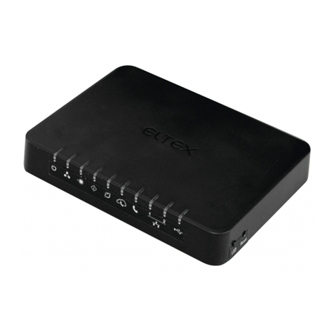
ELTEX ONT NTU-1 User manual

____________________________________________________________________________________
____________________________________________________________________________________
2NTU-1, NTU-1C Optical Network Terminals
Document version
Firmware version
Issue date
Content of changes
10.0
3.28.5
21 December 2021
Eleventh issue
9.0
3.28.4
06 September 2021
Tenth issue
8.0
3.28.3
14 July 2021
Ninth issue
7.0
3.28.2.2
13 January 2021
Eighth issue
6.0
3.28.1
13 November 2020
Seventh issue
5.0
3.28.0
20 August 2020
Sixth issue
4.0
3.26.5
27 April 2020
Fifth issue
3.0
3.26.4
30 January 2020
Fourth issue
2.0
3.26.1
13 March 2018
Third issue
1.1
3.24.1.232
22 May 2017
Second issue
System. IGMP packet losses that were occurred by
matching of MAC addresses with IGMP Querier
have been fixed
System. Multicast traffic prioritization has been
fixed
System. SSDP packets passing has been fixed
1.0
3.24.0.895
20 August 2015
First issue
Firmware version NTU-1(C) 3.28.5
NOTES AND WARNINGS
The notes contain important information, tips or recommendations on device operation and setup.
Warnings inform of the situations when actions may harm the device or a user, lead to fault
operation of the device or data loss.

____________________________________________________________________________________
____________________________________________________________________________________
NTU-1, NTU-1C Optical Network Terminals 3
CONTENTS
1 INTRODUCTION .............................................................................................................................................4
2 DEVICE DESCRIPTION ....................................................................................................................................5
2.1 Purpose ....................................................................................................................................................5
2.2 Device Specification .................................................................................................................................5
2.3 Key specifications.....................................................................................................................................6
2.4 Design.......................................................................................................................................................7
2.4.1 NTU-1 .............................................................................................................................................7
2.4.2 NTU-1C...........................................................................................................................................9
2.5 Light Indication.......................................................................................................................................10
2.6 Reboot and Reset to Factory Settings....................................................................................................11
2.7 Delivery Package ....................................................................................................................................11
3 NTU CONFIGURATION THROUGH WEB INTERFACE. USER ACCESS ............................................................12
3.1 The ‘Status’ menu. Information about the device status ......................................................................12
3.1.1 The ‘Device’ submenu. Device General Information ...................................................................12
3.1.2 The ‘PON’ submenu. Information on the status of the optical module ......................................13
3.2 The ‘LAN’ menu. LAN Interface Settings ................................................................................................14
3.3 The ‘Admin’ menu. Administration Settings..........................................................................................14
3.3.1 The ‘GPON Settings’ submenu. Settings GPON network Access .................................................14
3.3.2 The ‘Commit and Reboot’ submenu. Commit changes and rebooting the device......................15
3.3.3 The ‘Password’ submenu. Access Control Configuration (password settings)............................15
3.3.4 The ‘Firmware Upgrade’ submenu. Firmware Update................................................................15
3.4 The ‘Statistics’ menu..............................................................................................................................16
3.4.1 The ‘Interface’ submenu. Network Interface statistics ...............................................................16
3.4.2 The ‘PON’ submenu. PON interface statistics..............................................................................16
APPENDIX A –POSSIBLE PROBLEMS AND OPTIONS FOR THEIR SOLUTION ..........................................................17
TECHNICAL SUPPORT.............................................................................................................................................18
____________________________________________________________________________________
____________________________________________________________________________________
4NTU-1, NTU-1C Optical Network Terminals
1INTRODUCTION
GPON network belongs to one of the varieties of passive optical PON networks. This is one of the most
modern and effective solutions for "last mile", which allows significant savings on cable infrastructure and
provides data transmission speed of up to 2.5 Gbps downlink and 1.25 Gbps uplink. The use of GPON-based
solutions in access networks makes it possible to provide end users with new IP services together with
traditional ones.
The main advantage of GPON is the use of a single line terminal (OLT) for multiple subscriber devices
(ONT). OLT is a converter of Gigabit Ethernet and GPON interfaces, which serves to connect the PON network
with higher-level data transmission networks. The ONT device is designed to connect customers' equipment to
broadband access services. It can be used in residential areas and business centers.
This user manual describes the purpose, main technical specifications, configuration rules and monitoring
of NTU-1, NTU-1С, NTU-1C rev.B and NTU-1C rev.C (hereinafter NTU-1 and NTU-1C respectively) optical
terminals.

____________________________________________________________________________________
____________________________________________________________________________________
NTU-1, NTU-1C Optical Network Terminals 5
2DEVICE DESCRIPTION
2.1 Purpose
NTU-1, NTU-1C GPON ONT (Gigabit Ethernet Passive Optical Network) devices are high-performance
network terminals designed for connection with upstream GPON equipment and providing end user with
broadcast access services. GPON connection is established through the PON interface, while Ethernet interface
is used for connection of network devices. A distinctive feature of the NTU-1, NTU-1C user terminals is that the
devices might be powered through the twisted pair cable in an Ethernet network (over distance of up to 40
meters).
The key GPON advantage is the optimal use of bandwidth. The technology is the next step of high-speed
Internet connection for homes and offices. Designed to deploy a network inside home or office building, the
devices provide reliable connection with high bandwidth over long distances for users living and working in
remote apartment buildings and business centers.
NTU-1, NTU-1C devices have the following interfaces:
Table 1 –Interfaces configuration
Model Name
WAN
LAN
FXS
RF
Wi-Fi
USB
NTU-1
1 ×GPON
1 ×1Gigabit
-
-
-
-
NTU-1C
1 ×GPON
1 ×1Gigabit
-
1
-
-
2.2 Device Specification
The devices have the following interfaces:
–1 PON SC/APC port for connection to operator's network;
–1 Ethernet RJ-45 LAN ports 10/100/1000BASE-T for connection of network devices;
–For NTU-1C only: 1 RF port for CaTV service provisioning.
The terminal uses an external adapter for 220 V / 12 V power supply. It is also possible to power the device
via the Ethernet-cable UTP CAT-5E (when using GRT-120100A power module), the maximum distance –40
meters for NTU-1 and 25 meters for NTU-1C.
The device supports the following functions:
Network functions:
–bridge mode;
–support for QoS mechanisms;
–IGMP-snooping.
Firmware update via web interface, OMCI.
Remote monitoring, configuration, and setup via OMCI.
Fig.1 shows a diagram of the NTU-1, NTU-1C equipment connection.

____________________________________________________________________________________
____________________________________________________________________________________
6NTU-1, NTU-1C Optical Network Terminals
Figure 1 –Connection of NTU-1, NTU-1C
2.3 Key specifications
Table 2 lists key specifications of the terminals.
Table 2 –Key specifications
Parameters of Ethernet LAN Interface
Number of interfaces
1
Socket
RJ-45
Data rate
Auto-negotiation, 10/100/1000 Mbps,
duplex/half-duplex
Supported standards
IEEE 802.3i 10BASE-T Ethernet
IEEE 802.3u 100 BASE -TX Fast Ethernet
IEEE 802.3ab 1000 BASE-T Gigabit Ethernet
IEEE 802.3x Flow Control
IEEE 802.3 NWay auto-negotiation
Parameters of PON Interface
Number of PON interfaces
1
Supported standards
ITU-T G.984.x Gigabit-capable passive optical networks (GPON)
ITU-T G.988 ONU management and control interface (OMCI)
specification
FSAN Class B+
SFF-8472
IEEE 802.1Q Tagged VLAN
IEEE 802.1p Priority Queues
IEEE 802.1D Spanning Tree Protocol
Connector type
SC/APC
according to ITU-T G.984.2
Transmission medium
fiber optical cable SMF-9/125, G.652
Splitting ratio
up to 1:64
Maximum range of coverage
20 km

____________________________________________________________________________________
____________________________________________________________________________________
NTU-1, NTU-1C Optical Network Terminals 7
Transmitter:
1310 nm
Upstream connection speed
1244 Mbps
Transmitter power
from +0.5 to +5 dBm
Optical spectrum width (RMS)
1 nm
Receiver
1490 nm
Downstream connection speed
2488 Mbps
Receiver sensitivity
-28 dBm
Receiver Optical Overload
-4 dBm
Control
Local control
Web interface
Remote control
OMCI
Firmware update
OMCI, HTTP
Access restriction
By password
General parameters
Power supply
-12 V DC / 220 V AC power adapter;
-Remote power supply over Ethernet-cable UTP CAT-5E:
NTU-1
NTU-1C
up to 40m1
up to 25m1
Maximum power consumption
5 W
Operating temperature range
from +5 to 40 °C
Relative humidity
up to 80 %
Dimensions
(W ×H ×D)
NTU-1
112 × 32 ×100 mm
NTU-1C
160 × 40 × 124 mm
Weight
NTU-1
0.250 kg
NTU-1C
0.265 kg
2.4 Design
2.4.1 NTU-1
NTU-1 is designed as a 112 ×32 ×100 mm desktop device in a plastic housing.
Fig. 2 shows NTU-1 rear panel.
Figure 2 –NTU-1 rear panel
Connectors and controls located on the rear panel of NTU-1 are listed in Table 3.
1
When using GRT-130100A, SSM-1330-1000A PoE injectors

____________________________________________________________________________________
____________________________________________________________________________________
8NTU-1, NTU-1C Optical Network Terminals
Table 3 –Description of connectors and control elements located on the rear panel
Rear Panel Element
Description
1
12V
Connector for the power adapter
2
10/100/1000
RJ-45 10/100/1000BASE-T port for network devices connection
3
PON
SC port (socket) for connection to PON network
Fig. 3 shows NTU-1 side and top panels.
Figure 3 –NTU-1 top and side panels
Control elements and LED indicators located on the NTU-1 side and top panels are listed in Table 4.
Table 4 –Description of LEDs and control elements located on the side and top panels
Panel Element
Description
4
Power
Power supply indicator
5
Status
Device authentication indicator
6
Link Act.
Indicator of the Ethernet port
7
Speed
Connection data rate indicator
8
PON Link
Optical interface indicator
9
PON Alarm
Indicator of line network terminal connection status
10
Reset
A functional key that reboots the device and resets it to the factory settings

____________________________________________________________________________________
____________________________________________________________________________________
NTU-1, NTU-1C Optical Network Terminals 9
2.4.2 NTU-1C
NTU-1C series devices are designed as a 160 ×40 ×124 mm desktop device in a plastic housing.
Fig. 4 shows NTU-1C rear panel.
Figure 4 –NTU-1C rear panel
Connectors and control elements located on the rear panel of NTU-1C are listed in Table 5.
Table 5 –Description of connectors and control elements located on the rear panel
Rare panel element
Description
1
12V
Connector for the power adapter
2
F
A functional key that reboots the device and resets it to the factory
settings
3
RF port
Port for cable TV connection
4
10/100/1000
RJ-45 10/100/1000BASE-T port for connection of network devices
5
PON
PON SC port (socket) for connection to PON network
Fig. 5 shows NTU-1C top panel.
Figure 5 –NTU-1C top panel
Table 6 –Description of LEDs located on the top panel
Top panel element
Description
1
TV
CaTV signal indicator
2
PON Alarm
Indicator of line network terminal connection status
3
PON Link
Optical interface indicator
4
Link/Act.
Ethernet port indicator
5
Status
Device authentication indicator
6
Power
Power supply indicator

____________________________________________________________________________________
____________________________________________________________________________________
10 NTU-1, NTU-1C Optical Network Terminals
2.5 Light Indication
The indicators located on the top panel show the device current status.
Tables 7, 8 list possible statuses of the LEDs.
Table 7 –Light Indication of NTU-1 Status
LED
LED Status
Device Status
Power
off
Device is disconnected from the power source or faulty
Status
off
Device is loading or has default configuration
orange
Getting configuration by OMCI is in progress
red
An error occurred while configuration via OMCI
green
OMCI configuration has been successfully completed, the device operates properly
Link Act.
off
There is no connection to the LAN-port
green
Established LAN connection
flashes
Data transmission is in progress
Speed
off
There is no connection to the LAN-port
orange
Established 1000 Mbps connection
green
Established 10/100 Mbps connection
PON Link
off
No signal from optical line terminal
flashes slowly
Device is not registered on optical line terminal
green
A connection between optical line terminal and the device has been successfully
established
PON Alarm
off
A connection between optical line terminal and the device is established
red
No signal from optical line terminal
Table 8 –Light Indication of NTU-1C Status
LED
LED Status
Device Status
TV
off
RF port is off
red
СaTV signal power < -10 dBm or > +3 dBm
orange
СaTV signal power in the range of -10 dBm .. -8 dBm or +2 dBm .. +3 dBm
green
-8 dBm < CaTV signal power < +2 dBm
Power
off
Device is disconnected from the power source or faulty
Status
off
Device is loading or has default configuration
orange
Getting configuration by OMCI is in progress
red
An error occurred while configuration via OMCI
green
OMCI configuration has been successfully completed, the device operates properly
Link Act.
off
There is no connection to the LAN-port
green
Established 10/100 Mbps LAN connection
orange
Established 1000 Mbps LAN connection
flashes
Data transmission is in progress
PON Link
off
No signal from optical line terminal
flashes slowly
Device is not registered on optical line terminal
flashes rapidly
Data transmission is in progress
green
A connection between optical line terminal and the device has been successfully
established
PON Alarm
off
A connection between optical line terminal and the device is established
red
No signal from optical line terminal

____________________________________________________________________________________
____________________________________________________________________________________
NTU-1, NTU-1C Optical Network Terminals 11
2.6 Reboot and Reset to Factory Settings
To reboot NTU-1, press the Reset button once on the device side panel. To reset NTU-1 to factory settings,
press the Reset button and hold it for 7-10 seconds.
To reboot NTU-1C, press the F button once on the device rare panel. To reset NTU-1C to factory settings,
press the Fbutton and hold it for 7-10 seconds.
By default: IP address LAN –192.168.1.1, subnet mask –255.255.255.0.
2.7 Delivery Package
The basic delivery package of NTU-1, NTU-1C includes:
–NTU-1 or NTU-1C optical network terminal;
–220 V / 12 V power adapter;
–Installation and initial configuration guide.

____________________________________________________________________________________
____________________________________________________________________________________
12 NTU-1, NTU-1C Optical Network Terminals
3NTU CONFIGURATION THROUGH WEB INTERFACE. USER ACCESS
Device configuration requires accessing the device through a web browser, such as Firefox or Google
Chrome. Enter the device IP address in the browser address bar to do this (enter IP –192.168.1.1 and subnet
mask –255.255.255.0 if you have factory settings).
When the address is entered, the device requires user to log in.
User name: user, password: user.
In order to prevent unauthorized access to the device, it is recommended to change the password (see
section 3.3.3).
Given below is a general view of the device configuration window. A navigation tree for object settings is
on the left pane, while the settings to edit is on the right.
3.1 The ‘Status’menu. Information about the device status
3.1.1 The ‘Device’submenu. Device General Information
The tab displays the current status and some basic device settings.

____________________________________________________________________________________
____________________________________________________________________________________
NTU-1, NTU-1C Optical Network Terminals 13
System:
–Device Name;
–Uptime –operation time from the last device reboot;
–Firmware Version;
–CPU Usage –utilization of CPU in percent;
–Memory Usage –utilization of memory in percent.
LAN Configuration:
–IP Address –device address in local network;
–Subnet Mask;
–MAC Address –device’s MAC address.
Click the Refresh button to update the information.
3.1.2 The ‘PON’submenu. Information on the status of the optical module
This tab contains detailed information about PON interface.
–Vendor Name –optical module manufacturing company;
–Part Number –optical module model;
–Temperature –optical module temperature, °C;
–Voltage –power supply voltage, V;
–Tx Power –transmitted signal level (1310 nm), dBm;
–Rx Power –received signal level (1490 nm), dBm;
–Bias Current –bias current, mA.
Click the Refresh button to update the information.

____________________________________________________________________________________
____________________________________________________________________________________
14 NTU-1, NTU-1C Optical Network Terminals
3.2 The ‘LAN’menu. LAN Interface Settings
Use this tab to configure basic LAN interface settings (for example, IP-addresses, subnet mask and other
parameters).
–Interface Name;
–IP Address –device address in local network;
–Subnet mask;
–IGMP Snooping –turn on/off (enabled/disabled) IGMP Snooping function to monitor network multicast
traffic.
Click the Apply Changes button to accept changes.
3.3 The ‘Admin’menu. Administration Settings
3.3.1 The ‘GPON Settings’submenu. Settings GPON network Access
The tab is used to configure the parameters of the GPON network access.
–LOID
1
–logical object identifier (user name in GPON network);
–LOID Password1–password to access for the logical object ID (user password in GPON network);
–PLOAM Password –set a password to access the physical layer to operate, manage and carry out other
technical maintenance for the device;
–Serial Number –device PON serial number.
Click the Apply Changes button to accept changes.
Parameters on this tab are not recommended to be changed. Invalid settings will lead to the loss of
connection with line optical terminal!
1
Not supported in the current firmware version

____________________________________________________________________________________
____________________________________________________________________________________
NTU-1, NTU-1C Optical Network Terminals 15
3.3.2 The ‘Commit and Reboot’submenu. Commit changes and rebooting the device
The tab is used to commit changes to system memory and reboot your system.
To commit changes and reboot the device, click Commit and Reboot button. The rebooting process takes
few minutes to complete.
3.3.3 The ‘Password’submenu. Access Control Configuration (password settings)
Use the tab to change device access passwords.
To change the password, select a username, enter the current password to the Old Password field, then
enter new password to New Password and Confirmed Password fields.
Empty password field will disable the protection.
Click the Apply Changes button to accept and save changes and Reset button to cancel.
3.3.4 The ‘Firmware Upgrade’submenu. Firmware Update
This tab allows you to update your device firmware.
To update firmware, choose the firmware file: click Browse button, then click Upgrade.If you select an
incorrect file, you can delete it using the Reset button.
Do not disconnect the device from the power supply or reboot it while firmware is updating. The
firmware update takes few minutes after which the device will be rebooted automatically.

____________________________________________________________________________________
____________________________________________________________________________________
16 NTU-1, NTU-1C Optical Network Terminals
3.4 The ‘Statistics’menu
3.4.1 The ‘Interface’submenu. Network Interface statistics
This page shows the packet statistics for transmission and reception regarding to network interface.
–Interface –network interface name;
–Rx pkt –received packets;
–Rx err –received packets with errors;
–Rx drop –dropped incoming packets;
–Tx pkt –transmitted packets;
–Tx err –transmitted packets with errors;
–Tx drop –dropped outgoing packets.
Click the Refresh button to update information and click the Reset Statistic button to reset statistics.
3.4.2 The ‘PON’submenu. PON interface statistics
The tab displays the statistics of received and transmitted packets for the PON interface.
–Bytes Sent –the number of bytes transmitted;
–Bytes Received –the number of bytes received;
–Packets Sent –the number of packets transmitted;
–Packets Received –the number of packets received;
–Unicast Packets Sent –the number of unicast packets transmitted;
–Unicast Packets Received –the number of unicast packets received;
–Multicast Packets Sent –the number of multicast packets transmitted;
–Multicast Packets Received –the number of multicast packets received;
–Broadcast Packets Sent –the number of broadcast packets transmitted;
–Broadcast Packets Received –the number of broadcast packets received;
–FEC Errors –the number of errors corrected using the FEC (Forward Error Correction);
–HEC Errors –the number of errors corrected using the HEC (Header Error Checksum);
–Packets Dropped –the number of packets dropped;
–Pause Packets Sent –the number of PAUSE packets transmitted to adjust the bit rate;
–Pause Packets Received –the number of PAUSE packets received to adjust the bit rate.

____________________________________________________________________________________
____________________________________________________________________________________
NTU-1, NTU-1C Optical Network Terminals 17
APPENDIX A –POSSIBLE PROBLEMS AND OPTIONS FOR THEIR SOLUTION
Problem
Possible Cause
Solution
Entering router's IP
address (e.g. 192.168.1.1)
could not access to the
web interface.
The PC does not belong to
the IP subnetwork for
connection to the web
interface.
In the parameters of Internet connection on your
PC, set the address of the subnet 192.168.1.0/24.
Defective cable.
Check the physical connection by checking LEDs (all
LEDs should be on). If the LEDs are off, use another
cable. If your computer is switched off, LEDs may
also be off.
Access denied by your
firewall.
Disable firewall on your computer.
Forgotten/incorrect
password to the web
interface of the device.
_________
Reset the router to default settings using the F
button on the rear panel of NTU-1C or Reset button
for NTU-1. Unfortunately, all changes you made in
settings will be lost.

____________________________________________________________________________________
____________________________________________________________________________________
18 NTU-1, NTU-1C Optical Network Terminals
TECHNICAL SUPPORT
For technical assistance in issues related to handling Eltex Ltd. equipment, please, address to Service
Center of the company:
https://eltex-co.com/support/
You are welcome to visit Eltex official website to get the relevant technical documentation and software:
Official website: https://eltex-co.com/
Download center: https://eltex-co.com/support/downloads/
This manual suits for next models
1
Table of contents
Other ELTEX Touch Terminal manuals

ELTEX
ELTEX NTU-MD500P User manual

ELTEX
ELTEX LTP-16N Instruction sheet

ELTEX
ELTEX NTU-RG-5402G-W Quick start guide

ELTEX
ELTEX LTP-16N User manual

ELTEX
ELTEX LTP-8X Installation manual

ELTEX
ELTEX NTU-52V User manual

ELTEX
ELTEX NTU-RG-1421G-WZ User manual

ELTEX
ELTEX LTP-8X User manual

ELTEX
ELTEX NTU-1 User manual

ELTEX
ELTEX TAU-36.IP User manual