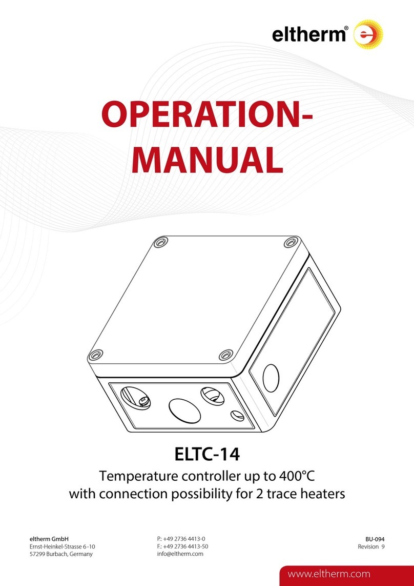
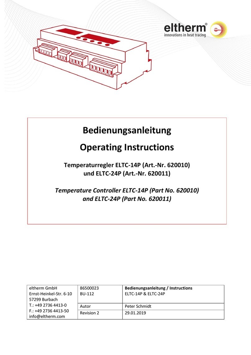
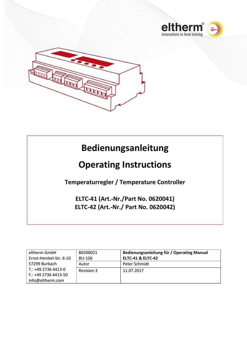
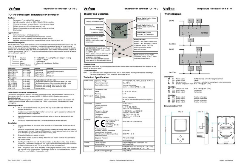
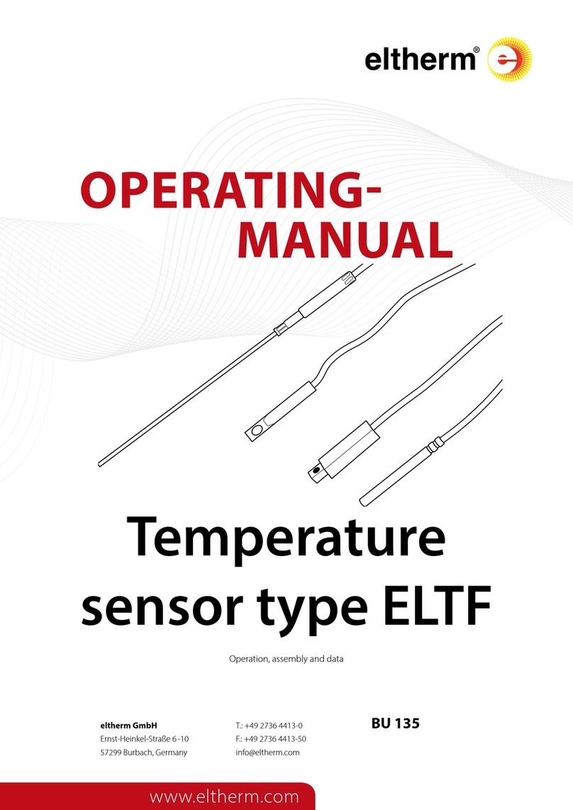
eltherm ELTC-14 User manual

page 1 of 9 008TA14 BU-094-A Révision : 7 Page 1 / 9
Operating Manual
Eltherm Electronic Temperature Controller
ELTC-14
Part Nos.: 0620007
eltherm Canada Inc.
1144 Appleby Line Unit E7
Burlington Ontario L7L 5H9
Canada
Phone: +1 (289) 812-6631
Fax: +1 (844) 325-6750
Internet: www.eltherm.com

page 2 of 9 008TA14 BU-094-A Revision : 7 Page 2 / 9
IMPORTANT SAFETY NOTES!
Please read this manual carefully before using this product. Warranty claims cannot be
considered if damage is caused by failure to comply with these operating instructions!
This documentation was compiled with the utmost care, however, we cannot guarantee for
its correctness in every respect.
Product Description
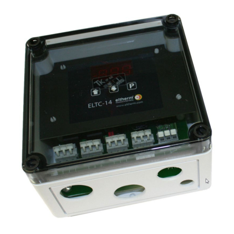
The eltherm Series EL-TC 14X electronic temperature controllers are designed for monitoring and control of
heating and heat tracing circuits. The temperature controller comes complete with a single circuit 20A
switching output and additional 8A alarm relay. The controller is designed to operate with 3-wire or 2-wire
Pt100 RTD temperature sensors (optionally supplied by eltherm). ELTC-14 series controllers are supplied fully
integrated in weather-proof enclosures, suitable for wall mounting, complete with transparent cover to allow for
viewing and access to the front panel and user interface of the controller.
Controller Operation
Operation of the controller and the user interface is very simple. After power-on, the type/model number of the
controller appears on the front panel of the device (displays “
C14”
), followed by a 3 second delay after which
the actual temperature will be displayed. Pressing the programming (
P
) button allows for viewing of the
temperature set point, displayed as ‘Set’, followed by the set point temperature. The menu automatically
returns to the main display (actual temperature) after 5 seconds. Access to the controller parameter list is
achieved by pressing and holding the “P” button for 3 seconds (after which “P10” appears on the display).
Pressing and holding button “P” for an additional 3 seconds provides display “P” of “dC” for degrees
Centigrade or “dF” for degrees Fahrenheit.
ELTC-14 Display / User Interface
LED (1) ON
Heater Relay ON
LED Blinking
Function Delayed
Increases Values
Decreases Values
Programming Mode
1
4
LED (4) ON
Alarm Relay Activated
LED blinking
Function Delayed

page 3 of 9 008TA14 BU-094-A Revision : 7 Page 3 / 9
Operational Description
The controller (via relay K1) will automatically switch the heating circuit ON when the actual temperature (
P01
)
falls below the control temperature setpoint (
P10
minus hysteresis
P11
).
In the event of an error condition, the integrated alarm relay
(K2)
switches (via the SPDT contact, configurable
as either NC or NO) to indicate one or all of the following error conditions:
- over / under temperature
- sensor-interrupt
- short circuit.
During sensor malfunction, relay K1 switches/cycles continuously on or off, depending on configuration.
Changing Parameters
To access and view the controller parameter list, press and hold the „P“ button for 3 seconds until „P10“
appears on the display
.
The following key strokes may be entered for viewing and adjusting* parameter
values. Refer to Page 5 of this manual for a complete list of controller parameters.
Parameter Protection
The temperature control set point (high/low set points, or P13 and P14 respectively) may be changed without
passcode protection, and set points may be changed using the procedure described above.. All other
parameters are passcode protected. The display will prompt when a passcode is required (display will indicate
„C00“).
To enter the passcode, use the arrow keys to enter the passcode number (C42). Confirm by pressing the “P”
button.
If no key is entered, the access code request is automatically cancelled after approx. 1 minute and the display
returns to the normal view.
•Press and hold „P“ for 3 sec.
- Parameter No. appears (P10)
•„▲ / ▼ “
- Pushing the ‘up’ or ‘down’ arrows allow for scrolling through the parameter list (P1 – P34)
•Press „P“ again
- Displays the programmed/set parameter value
•„▲ / ▼ “
- Pushing the ‘up’ or ‘down’ arrows will ‘increase’ or ‘decrease’ the parameter values accordingly
•Press „P“ again
- Saves the new value/set point, the display reverts back tothe adjusted parameter No.
•Press „▲ / ▼“ until „P1“ appears, then press “P” (or wait for less than 1 Min.)
-
Exits the settings menu

page 4 of 9 008TA14 BU-094-A Revision : 7 Page 4 / 9
Autoscrolling
Menu values scroll through the menu by keeping the ‚▲ / ▼'-keys depressed .
Error Messages
When an error condition occurs, the display will indicate the error code after an approx. 20 second delay.
Error Code Messages
E01 RTD/Pt100 temp sensor short circuit or temperature below -76°F (-60°C)
E02 RTD/Pt100 temp sensor interrupt (open) or temperature above 770°F (410°C)
E03 Temp. sensor third wire missing/not connected or Resistance (R) is equal to or above 10 ohms
C00 passcode entry required
E07 Alarm/Fault relay K1 open
E08 Alarm/Fault relay K1 short circuit
E09 Internal error
Error codes E07...E09: controller fault condition.
Check device/controller type
After controller is energized, the controller model/type number appears (
C14 for model ELTC-14
), followed by
a 3 second delay after which the actual temperature will be displayed.
Switching Temperature Scales (degF to deg C / deg C to deg F)
Changing sensor probe type (P20) automatically changes the temperature scale and associated set
points to the respective temperature scale (e.g. sensor type 0 and 1 display in deg C / sensor type 2
and 3 display in deg F).

page 5 of 9 008TA14 BU-094-A Revision : 7 Page 5 / 9
Parameter List and Description
Releasing Relay Mode
P01
..
Actual Sensor Temp
. °C/°F (disp.only)
P10
..
Control Setpoint
Affects relay 1, range P13...P14, [41°F/5°C]
P11
..
Switching hysteresis from set point (
P10)
range 2..10K [2K]
P12
..
Min. Relay Idle Time (Relay K1)
0..30.0 Min., [0.0 Min], resolution 0.1 min.
P13
Highest Adjustable Control Setpoint
Range min (see P14) to max 734°F (390°C), [734°F/390°C]
P14
..
Lowest Adjustable Control Setpoint
Range -58°F (-50°C) to max (see P13), [32°F/0°C]
P20
..
Sensor/Probe Type
0 = RTD/Pt100, 3-wire, °C (Resolution 1K)
[1] = RTD/Pt100, 2-wire, °C (Resolution 1K)
2 = RTD/Pt100, 3-wire, °F (Resolution 2°F)
3 = RTD/Pt100, 2-wire, °F (Resolution 2°F)
P21
..
Sensor Correction
-30...+10K, [0]
P30
..
High Temp. Alarm Threshold
Min or P31 to 752°F (400°C), [752°F/400°C]
P31
..
Low Temp. Alarm Threshold
-76°F (-60°C) to max or P30, [-76°F/-60°C]
P32
..
Alarm Delay while in Operation
0...99 min., [0.0 Min., Resolution 0.1 Min.]
P33
..
Alarm Delay while Power-on/Energized
0...500 min., [0 min.]
P34
..
Alarm Relay Mode (Relay K2)
0 = Relay ON at probe fault
[1] = Relay OFF at probe fault
2 = Relay works as releasing relay
Values in […] are factory set default settings

page 6 of 9 008TA14 BU-094-A Revision : 7 Page 6 / 9
In this mode (when
P34 =
2) relay K2 switches independently from alarm delay timers (P32 and P33) when the
actual high/low temp threshold ranges are between high and low set points P30 and P31.
Alarm Relay Modes
(
P34
= 0 or 1): If, after initial power on, the actual temperature falls below the low temp alarm threshold (P31),
the alarm delay (P33) is used as the alarm relay to provide additional time for warm-up. In normal operating
conditions, the alarm delay P32 is used as an alarm delay parameter.
Controller Technical Data / Specifications
Controller Type/Model
ELTC-14
Operating Voltage
100…240 VAC, 50/60 Hz
Power Consumption
max. 5 W
Relay K1
20A resistive/ max 250 VAC
RelayK2
8A resistive / max. 250 VAC
ambient temperature
-13 to 131°F (-25 to.+55°C)
storage temperature
-22 to 140°F (-30 to.+60°C)
adjustable range
32 to 734°F (0 to 390°C), optional configuration
display range / resolution
-58 to 752°F (-50 to 400°C)
accuracy
± 1K, ± 2 digits -58 to 752°F (-50 to 400°C)
display / relay indicators
LED (red), 11mm
terminals
Sensor: AWG 16…24 copper wire, length (exposed wire) 3/8” (9 to 10mm)
Others: AWG 14…24 copper single-wire, length (exposed wire) 1/4”
(5…6mm)

page 7 of 9 008TA14 BU-094-A Revision : 7 Page 7 / 9
Installation/ Safety Instructions
•Electrical installation and commissioning must be performed by authorized personnel only
•Please note and adhere to alllocalelectrical safety requirements!
•Please note maximum ratings as per provided type label!
•Observe ingress protection (IP) and NEMA rating requirements and permitted operating
temperature when choosing the location of the controller. Recommended and preferred
mounting locations include protection against precipitation and direct sunlight. Operate
only with closed lid, tightened cable entries and installed seals
•Avoid tension and pulling stress of the cables terminatedto the controller
•If the sensor cables need to be extended, use a shielded cable and connect one end of
the shield to a ground terminal near the controller. Do not install the cable in parallel with
main AC voltage wiring. The totalsum of wire resistance should not exceed 10 ohms. When
power is connected to the controller, the front panel will display the actual sensor temperature.

page 8 of 9 008TA14 BU-094-A Revision : 7 Page 8 / 9
ELTC-14 Parts List and Connection Details
Controller Model
Assembly Description
Item/Part No.
ELTC-14
2 cable glands M25x1.5
2 cable glands M20x1.5
1 cable gland M12x1.5
2 O-rings M25
2 O-rings M20
1 O-ring M12
2 multiple seals 2x1/4“ (2x6 mm)
1 locking nut M20x1.5
1 locking nut M25x1.5
0620007
Dimensions
Electrical Connection
M12x1.5 : clamping range
1/8“…1/4“ (3…6.5mm)
M25x1.5 : clamping range
1/4"…1/2“ (6…13mm)
M20x1.5 : clamping range
1/4"…1/2“ (6…12mm)
100 –240VAC

page 9 of 9 008TA14 BU-094-A Revision : 7 Page 9 / 9
Electrical Connection Board Descriptions
X1.1
X1.2
X1.3
X2.1 AC supplyLine or Hot (L or H)
X2.2 Connection Heating Cable A
X2.3 Connection Heating Cable B
X3.1
X3.2
X3.3
X4.1 Alarm RelayCOM
X4.2 Alarm RelayNC
X4.3 Alarm RelayNO
X5.1 Connection RTD / PT100 Sensor
X5.2 Connection RTD / PT100 Sensor
X5.3 Connection RTD / PT100 3-Wire (not required when using 2-wire-sensor)
Common/ Line Neutral (N)
Common Ground Protection (PE) Connection
Other manuals for ELTC-14
2
This manual suits for next models
1
Table of contents
Other eltherm Temperature Controllers manuals
eltherm
eltherm ELTC-W User manual

eltherm
eltherm Ex-TC It Series User manual

eltherm
eltherm ELTC-41 User manual

eltherm
eltherm ELTC/L-15 User manual

eltherm
eltherm ELTC-14 User manual

eltherm
eltherm ELTC-14P User manual

eltherm
eltherm ELTC-14P User manual

eltherm
eltherm ELTC-15 User manual

eltherm
eltherm ELTC/H-14 User manual
eltherm
eltherm ELTF User manual