emaux SPV150 User manual

SUPER-POWER
With Wi-Fi and MODBUS
Swimming Pool
Variable
Speed Pump
USER MANUAL
NSF only apply for NSF version

P a g e | 2
Table of Contents Page
WARNINGS AND SAFETY INSTRUCTIONS 3
1. SPV150 VARIABLE SPEED PUMP OVERVIEW 5
2. PRODUCT INFORMATION
3. IMPORTANT SAFETY INSTRUCTIONS 7
4.
INSTALLATION
4.1 PIPING 7
4.2 Electrical Wiring 8
5. START UP 10
. ROUTINE MAINTENANCE 11
7. WINTERIZING
8. CONTROL AND DISPLAY PANEL
8.1 OVERVIEW 12
8.2 PROGRAM FLOW CHART 13
9. OPERATION PROCEDURE
9.1 POWER UP 14
9.2
CLOCK SETTING
14
9.3 PRESET SPEED 1-3 15
9.4 CHANGE PRESET SPEED 1-3 15
9.5 SETTING SCHEDULE 15
9. SCHEDULE POLICY 15
10. PRIMING SETTING
10.1 PRIMING TIME 17
10.2 PRIME SPEED 17
10.3 PRIMING ENABLE / DISABLE 17
11 SVRS
(
SAFETY VACUUM RELEASE SYSTEMS
)
SETTING 18
12 RS485 SETTING (FOR RS-485 VERSION)
12.1 SLAVE ADDRESS 18
12.2 BAUD RATE 19
13. WIFI SETTING (FOR WIFI VERSION) 19
14. FREEZE PROTECTION 19
15. FIRMWARE VERSION AND DATE 19
1 .
SYSTEM RESET TO FACTORY DEFAULT SETTING
20
17. AUTO-RECOVERY 20
18. ERROR MENU 21
19. ERRORS DESCRIPTION
19.1 COMMUNICATION ERROR 21
19.2 OPERATION ERRORS 21
20.. WI-FI CONNECTION (for WIFI version)
20.1 ENABLE WI-FI 22
20.2 Wi-Fi Direct CONNECTION 22
20.3 APPLICATION INTERFACE 22
20.4 CHANGE SSID AND PASSWORD 24
20.5 CONNECT TO HOME NETWORK 24
20. Connectivity Specification 25
21. RS-485 CONNECTION (FOR RS-485 VERSION ) 25
22. AFTER-SALES SERVICE 2
23. REPLACEMENT PARTS 2
24 TROUBLE SHOOTING 27
25 WARRANTY POLICY 28
25
.1
EXCEPTIONS THAT MAY RESULT IN DENIAL OF A WARRANTY CLAIM
28
25.2 CLAIM PROCESS 28
25.3 WARRANTY OBLIGATION 29
25.4 WARRANTY OR REPRESENTATIONS BY OTHERS 29

P a g e | 3
WARNINGS AND SAFETY INSTRUCTIONS
GENERAL WARNING
This instruction contain general caution information for use in Pool and SPA pump installation application.
Specified Pump model function should be refer to particular manual. Components such as the filtration
system, pumps and heater must be positioned so as to prevent their being used as means of access to the
pool by young children.
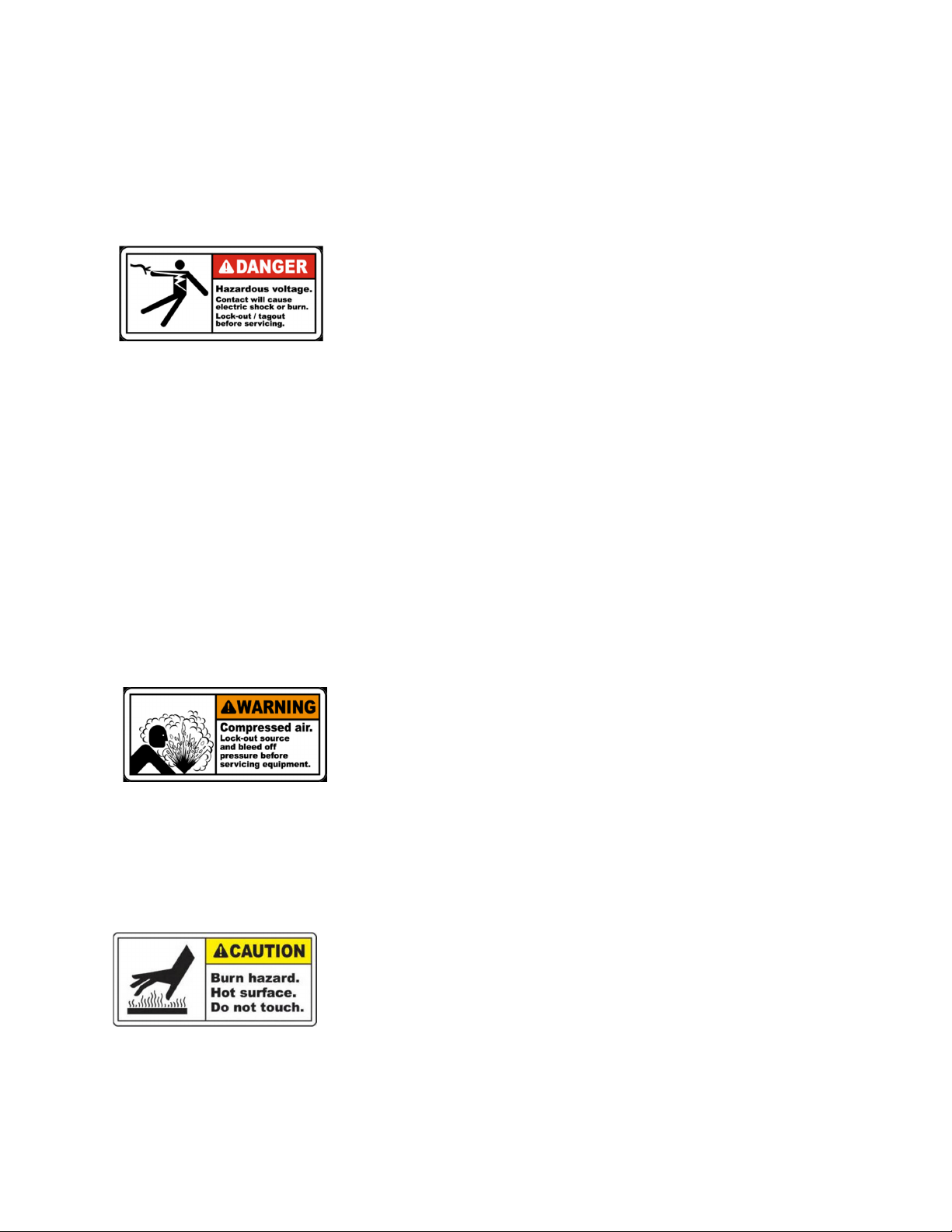
RISK OF ELECTRICAL S OCK
This appliance should be installed by qualified electrical personnel in
accordance with National Electrical Code and all applicable local codes and
ordinances. Hazardous voltage can shock, burn, and cause death or serious
property damage. DO NOT use an extension cord to connect unit to electric
supply to reduce the risk of electric shock.
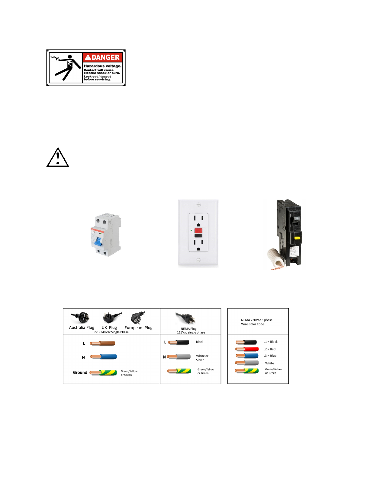
•The pump should be permanently connected to an individual circuit breaker.
•Pump must be connected to a residual current device (RCD) having a rated residual operating current
not exceeding 30 mA or receptacle with ground fault circuit interrupt (GCFI).
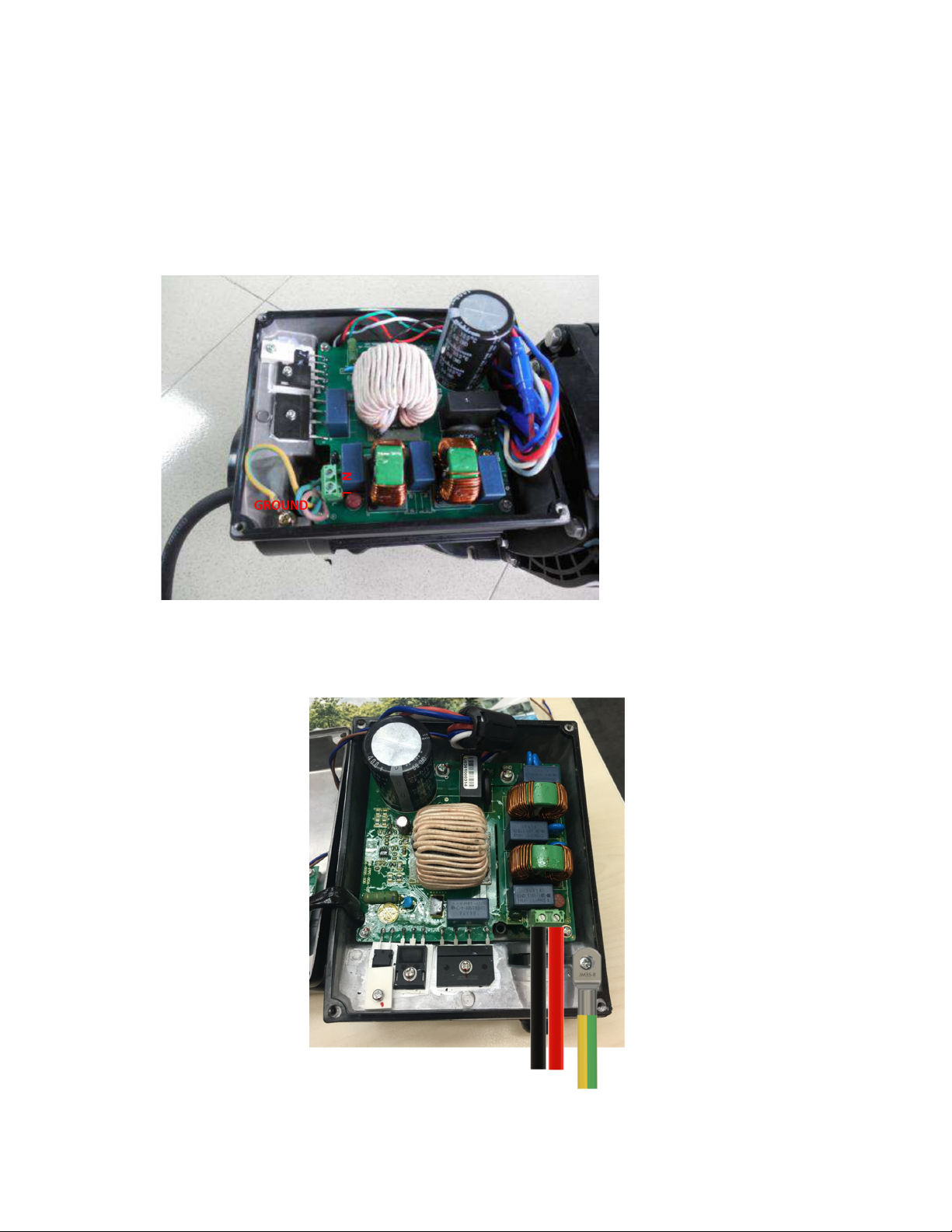
•Electrical grounding must be connected before connecting to electrical power. Failure to ground all
electrical equipment can cause serious or fatal electrical shock hazard.
•Bonding: Use at least #8 AWG (# AWG for Canada) a solid copper conductor, run a continuous wire
from external bonding lug (if available) to the pressure wire connector provided on the electrical
equipment and to all metal parts of swimming pool, spa, or hot tub, and metal piping (except gas piping),
and conduit within 1.5 m (5 ft) of inside walls of swimming pool, spa, or hot tub.
•Never open the inside of the drive motor enclosure. There is a capacitor bank that holds a mains supply
voltage charge even when there is no power to the unit. The voltage should be referred to the individual
pump operation voltage.
•The pump is capable of high flow rates; use caution when installing and programming to limit pumps
performance only.
•Switch OFF pump power before servicing and disconnecting the main circuit to the pump.
•Never change the filter control valve position while the pump is running
COMPRESS AIR AZARDOUS
This system enclosed pre-filter / filter and become pressurized. Pressurized
air can cause the Lid to separate which can result in serious injury or
death.
STAND CLEAR OF PUMP DURING START-UP
Pool and spa circulation systems operate under high pressure. When any part of the circulating system (i.e.
lock ring, pump, filter, valves, etc.) is serviced, air can enter the system and become pressurized. Filter tank
Lid and pre-filter cover must be properly secured to prevent violent separation. Place pre-filter / filter air
relief valve in the open position and wait for all pressure in the system to be relieved before remove the lib
to access the basket for cleaning.
YPERT ERMIA
SPA water temperature excess 38°C (104°F) may be injurious to health.
Measure water temperature before entering SPA.
Hyperthermia occurs when the internal temperature of the body reaches a level several degrees above the
normal body temperature of 98. °F (37 °C). The symptoms of hyperthermia include drowsiness, lethargy,
and an increase in the internal temperature of the body.

P a g e | 4
SUCTION ENTRAPMENT AZARD
This pump produces high levels of suction and creates a strong vacuum at
the main drain at the bottom of your pool and spa. This suction is so strong
that it can trap adults or children under water if they come in close proximity
to a pool or spa drain or a loose or broken drain cover or grate.
The Virginia Graeme Baker (VGB) Pool and Spa Safety Act creates new requirements for owners and operators of
commercial swimming
Pools and spas.
Commercial pools or spas constructed on or after December 19, 2008, shall utilize:
(A) A multiple main drain system without isolation capability with suction outlet covers that meet ASME/ANSI
A112.19.8a Suction Fittings for Use in Swimming Pools, Wading Pools, Spas, and ot Tubs and either:
(i) A safety vacuum release system (SVRS) meeting ASME/ANSI A112.19.17 Manufactured Safety Vacuum
Release systems (SVRS)
For Residential and Commercial Swimming Pool, Spa, ot Tub, and Wading Pool Suction Systems and/or
ASTM F2387 Standard
Specification for Manufactured Safety Vacuum Release Systems (SVRS) for Swimming pools, Spas and ot
Tubs or
(ii) A properly designed and tested suction-limiting vent system or
(iii) An automatic pump shut-off system.
Commercial pools and spas constructed prior to December 19, 2008, with a single submerged suction outlet
shall use a suction outlet cover that meets ASME/ANSI A112.19.8a and either:
(A) A SVRS meeting ASME/ANSI A112.19.17 and/or ASTM F2387, or
(B) A properly designed and tested suction-limiting vent system, or
(C) An automatic pump shut-off system, or
(D) Disabled submerged outlets, or
(E) Suction outlets shall be reconfigured into return inlets.
There are five types of suction entrapment according to The Virginia Graeme Baker (VGB) Pool and Spa
Safety Act
• Body Entrapment a section of the torso becomes entrapped
• Limb Entrapment an arm or leg is caught by or pulled into an open drainpipe
• air Entrapment or entanglement hair is pulled into and/or wrapped around the grate of the drain
cover
• Mechanical Entrapment the bather’s jewelry or clothing gets caught in the drain or the grate
• Evisceration the victim's buttocks come into contact with the pool suction outlet and he or she is
disemboweled
WARNING: TO REDUCE ENTRAPMENT AZARD RISK
Two function suctions outlets per pump must be installed to prevent entrapment. The
minimum separate of suction on the same plate must be at least point to point
measurement 1 meter (3ft) apart. It is used to avoid “dual blockage” by bather.
If suction is found damage, broken, cracked, missing or not securely attached during regular checking,
shunt down the pool and replace it immediately.
A vacuum release or vent system is recommended to install for suction entrapment release.

P a g e | 5
1.
SPV150 VARIABLE SPEED PUMP OVERVIEW
Super-Power Series Variable Speed Pump provides the best energy saving solution from over-usage and to increase
efficiency and reduce maintenance cost. Traditional single speed pump runs at maximum load continuously. It is
inefficient and leads to a higher running cost compare to Emaux Super-Power Variable Speed Pump. Reduced
speeds (rpm) provide a slower water circulation rate that put less strain on the complete installation such as
filtration, sanitization, and plumbing. It reduces the wear and tear factor and resulting in a cost saving to the pool
owner.
Wireless Wi-Fi connectivity capability in Wi-Fi Direct AP Mode and Home network STA mode to access menu and
control the pump over any Wi-Fi device with web browser.
Wired RS485 MODBUS protocoled for automation connectivity.
Enhanced features:
Freeze Protection to prevent piping damage by water frozen, and
Safety Vacuum Release Systems (SVRS) to stop the pump when entrapment occur in the pool and detected
by the pump to stop the circulation.

P a g e | 6
2. PRODUCT INFORMATION
Dimensions
Performance Curve
Code
Model
Voltage/
Frequenc
y
Max Load
Current
Connection
ID/OD
Input
Power
orse
power
RPM
88029807
SPV150
220-240V
50/ 0 Hz 5.9-5.4A
1.5’’/2”
50mm/ 3mm
1.30 (kW)
1.5 hp
800-3400
RPM
9023302 SPV150-RS485
9032203 SPV150-WIFI+RS485

P a g e | 7
3.
IMPORTANT SAFETY INSTRUCTIONS
Warning:
The user guide you are holding includes essential information on the safety
measures to be implemented for installation and start-up. Therefore, the installer as well as
the user
must read the instructions before beginning installation and start-up.
Keep this
manual for future reference.
The pump should be installed according to your local electrical installation ordinances and regulations.
Only qualified, licensed personnel should install the pump and the wiring.
This appliance cannot be used by persons (including children) with reduced physical,
sensory or
mental capabilities or lack of experience and knowledge unless they have been given supervision or
instruction concerning use of the appliance in a safe way and understand the hazards involved.
Children must not play with the appliance.
Warning: This appliance can be used by children aged from 8 years and above and persons with
reduced physical, sensory or mental capabilities or lack of experience and knowledge if they
have been given supervision or instruction concerning use of the appliance in a safe way and
understand the hazards involved. Children shall not play with the appliance. Cleaning and user
maintenance shall not be made by children without supervision.
4. INSTALLATION
4.1 Piping
•
Install the pump as close to the pool as possible, preferably in a dry, well ventilated area away
from direct
sunlight. Protect the pump from excessive moisture.
•
Place the pump as close to the water
source as possible, so that the suction pipe
is short,
straight and direct to reduce the
friction loss. Don't install the pump at more
than 10 ft (3 meters) of
geometrical height
from water level.
•
Before installing the pump, make sure
that the surface is solid, elevated, rigid
and vibration
free.
•
Secure the pump to the base with screws
or bolts to limit the vibration and the
stress on the
pipe or the joints.
•
Leave enough space for gate valves in suction and discharge piping, if required.
•
Connect the suction and discharge pipe to the outlet and inlet of the swimming pool.
•
Make sure that floor drainage is adequate to prevent flooding.
•
Make sure that the pump and piping are accessible for servicing.
Note: The pump suction and discharge connections are mounded in thread
stops, DO NOT
try to screw the pipe beyond these stops.
The two sets 1.5” union adaptor are universal design for metric and imperial
PVC pipe connection.

P a g e | 8
4.2 ELECTRICAL WIRING
Warning: This power pump demand licensed or certified electrician
or qualified pool installer to ensure there is adequate protection
between the pump motor and mains power supply according to
individual countries safety code.
The pump has power cord with plug attached on the plug, plug it to a
power socket with circuit breaker to isolate the motor from the mains power for over load
protection. The circuit breaker rating should refer to the electrical specification of individual
pump working voltage and power.
The power has to be with a Residual Current Device (RCD) or Ground Fault Circuit Interrupt (GFCI)
having a rated residual operating current not exceeding 30 mA.
If the RCD/GFCI device trips, it means there is fault on the power line or motor. Do not use this
pump. Disconnect the pump and have the problem corrected by a qualified service
representative before using. Press the reset button to reset the RDC/GFCI devices after fixed. It
will keeps the circuit shut off and will not reset if the power line problem is not fixed.
It is recommend to test the RCD/GFCI at least once a month.
RCD
NEMA GFCI R
eceptacle
NE
MA GFCI
Breaker
Pumps should be shipped with Power cord with plug for corresponding countries. If there is not power
cord attached to the pump, it is necessary to follow the local electricity power line color code to
connect the power according to the wiring for individual pump diagram.

P a g e | 9
4.2 Electical WIRING
It is a 220-240Vac 50/ 0Hz electric power operate variable speed pump.
Unscrews the four corners screw of the variable sped driver box to open it. There are three terminals
labelled as L, N and GROUND. Connect the power wires to these terminals according to the electrical
code.
For single phase 220-240Vac 50Hz, the pump is shipped with power cord and there is no need to wire
the power cord, just need to plug the power plug to a RCD protected socket.
j
MENA ardwired
230Vac 0Hz two phase hardwired connection, open the cover of the drive. Follow to NEC protocoled,
connect L1 to L, L2 to N and Earth to Ground on metal case.

P a g e | 10
5.
START UP
•
Verify the pump shaft turn freely.
•
Check the mains voltage, current and frequency are accordingly to the name plate.
•
Never run pump dry! Running pump dry may cause damage to the mechanical seal causing leakage and
flooding. Fill the pre-filter with water before starting motor.
•
Before removing the pre-filter Lid, STOP PUMP, CLOSE GATE VALVES in suction and discharge pipes.
•
Always STOP THE PUMP before when RELEASE ALL PRESSURE from the pump and the piping system
before proceeding.
•
Never tighten or loosen screw while the pump is in operation.
•
The suction pipe and the suction inlet in the pool must be free from obstruction.
WARNING: Tighten
/
untighten the pump Lid by hand only.
WARNING:
Before start-up, the alignment of the pump should be checked. The tubing should be
inspected to ensure that they are properly fitted and tightened and that they do not exert pressure or
tension on the pump's suction or discharge connection. The pump should never be operated.
I. Clear all piping of construction debris and verify that the piping has passed a proper pressure
test.
II. Check the filter and other equipment for proper installation, verifying all clamps and
connections are properly installed as per the manufacturer's instructions.
III. Open any shut off valves on the suction and discharge lines.
IV. Open the filter pressure relief valve and release all pressure from the system.
V. If the pump is located below the water level of the pool, opening the pressure relief valve will
fill the pump with water.
VI. If the pump is located above the pool water level, remove the Lid from the pre-filter and fill
with water before starting the pump.
VII. Check to see that the Lid O-ring and seat areas are clean and lubricated. Debris in the sealing
area can cause air to leak into the system and make it difficult to prime the pump.
VIII. Close/tighten the Lid to make an airtight seal.
IX. Turn on power wait for pump to prime, which can take up to fourteen (14) minutes at 10 ft
(3m) vertical lift of 1.5” inlet piping. Priming will depend on vertical length of suction lift and
horizontal length of suction pipe. If pump does not prime within prime time, stop the motor
and determine cause.
X. If the pump does not prime within 15 minutes. Ensure all instructions to this point have been
followed. Stop the pump! Check for suction leaks and repeat steps (I) through (VIII).

P a g e | 11
6. ROUTINE MAINTENANCE
The pump mechanical seal requires no lubrication and service.
The only routine maintenance needed is the inspection and cleaning of the
pre-filter basket. Debris or trash collected in the basket will choke off the
water flow through the pump. Follow the instructions below in order to clean
the pre-filter basket:
i.
Turn off the pump, close the gate valve in suction and discharge,
and release all pressure from the system before proceeding.
ii.
Lose the suction inlet hose or piping.
iii. Turn the transparent Lid nut anti clockwise to release by hand and
lift the transparent Lid up.
iv. Remove the pre-filter basket and cleaning. Make sure all the holes in
the basket are clear, flush the basket with water. Put back the basket
with the guideline on the edge of the basket. If the basket is placed
not properly, the transparent Lid and Lid nut will not fit well and air
leakage should occur.
v. Clean and inspect the Lid’s O-ring ring; reinstall on the transparent Lid .
vi. Clean the ring groove on the pre-filter body and replace the Lid. To help keep the Lid from sticking, tighten
it by hand only.
vii. Connect back the suction hose or pipe. Water should flood the pump body and restart the pump.
7. WINTERIZING
If the air temperature drops below 0°C (35°F), the water in the system can freeze and cause damage.
Freezing damage is not warrantable.
To prevent freezing damage follow the procedures listed below:
Shut off electrical power for the pump at the house circuit breaker.
Drain the water out of the pump case by removing the two drain plugs from the case.
Store the plugs in the pump basket.
Cover the motor to protect it from severe rain, snow and ice.
If it is possible, store the pump in a dry location during this time.
Do not wrap the motor in plastic. It will cause condensation and rust on the inside of the motor.

P a g e | 12
8. CONTROL AND DISPLAY PANEL
8.1
OVERVIEW
The panel include the below display or control function to monitor and control the pump running status.
a)
Clock: Real Time Clock display
b)
Running Status: Running speed and power rating display
c)
Pre-set Speed: 3 pre-set running speeds.
d)
Function settings:
Real time clock, 3 pre-set speeds, 2 schedule settings, NO flow, self- priming
settings, SVRS and Freeze protection
e) Error display: Overcurrent, Overvoltage, Under-voltage, Overheating fault code.
f) Auto-recovery: After an overcurrent, Overvoltage, Under-voltage, Overheating or Power failure, the
settings will be restored as before the error.
g) Power failure recovery: When there is a power is interrupt, the pump will be restored as before
when power resume.
h) Wi-Fi : Wi-Fi ready indication after start up
i) RS485 Connection:
external automation control over MODBUS
CONTROLLER DISPLAY

P a g e | 13
8.2 PROGRAM FLOW C ART
Self
-
Checking Interface
Monitor Interface
Speed Display
Power Consumption Display
Time Display
Default:
“
SP:1000
”
Unit: RPM
Setting Interface
Schedule 1 Speed
Schedule 1 Time On
Schedule 1 Time Off
Schedule 1 Enable/Disable
Schedule 2 Speed
Schedule 2 Time On
Schedule 2 Time Off
Schedule 2 Enable/Disable
Speed 3
Priming Time
Self
-
Priming Speed
Self
-
Priming Enable/Disable
SVRS Alarm Time
SVRS Sensitivity
SVRS Reset Time
SVRS Reset Speed
SVRS Enable / Disable
MODBUS Slave Address
MODBUS Baud Rate
Freeze Protection duration
Freeze Protection Temperature
Freeze Protection Speed
Firmware Version
Version Date
Reset
Display:
“
P: 0
”
Unit: Watt
Display:
“
CL: 0:00
”
Default:
“
1E:off
”
Range: on / off
Default:
“
1O: 0:00
”
Range: 00:00~23:59
Default:
“
1F: 0:00
”
Range: 00:00~23:59
Default:
“
1S:1500
”
Range: 800-3400rpm
Default:
“
2E:off
”
Range: on / off
Default:
“
2O: 0:00
”
Range: 00:00~23:59
Default:
“
2F: 0:00
”
Range: 00:00~23:59
Default:
“
2S:2400
”
Range: 800-3400rpm
Default:
“
3S:3400
”
Range: 800-3400rpm
Default:
“
PL: 2
”
Range: 1~20 min
Default:
“
PS:2900
”
Range: 2900~3400rpm
Default:
“
PE: on
”
Range: on/off
Default:
“
SL: 1
”
Range: 1~999 sec
Default:
“
SS: 1
”
Range: 1~100%
Default:
“
SR: 30
”
Range: 30~999 sec
Default:
“
SV: 800
”
Range: 800-3400rpm
Default:
“
SE: off
”
Range: on/off
Default:
“
EA: 2
”
Range: 1~247
Default:
“
Eb: 9 00
”
Range: 1~999 sec
Default:
“
RE: off
”
Range: on/off
Default:
“
RL: 4
”
Range: 1-8 hour
Freeze Protection enable/Disable
Default:
“
RT: 4
”
Range: 1-10°C
Default:
“
RS: 1800
”
Range: 900-3400rpm
Display
“
RESET
”
3 sec
Press and hold
2 sec
Press
“
Mode
”
to switch
Press
/
to change
Editing Interface
The Data format will be
changed accordingly to
the program selected, the
relevant data will be
flashing.
Press
“
Mode
”
to confirm
Press “Speed 3” to Cancel
Press and Hold
“Mode” for 2 second
Enter Time
Setting Interface
WIFI Enable/Disable
WIFI Reset
Default:
“
FI: on
”
Range: on/off
Display
“
RESET
”

P a g e | 14
9. OPERATION PROCEDURE
9.1
POWER UP
Plug in power and the pump will do self-diagnostic checking.
•If there is error, it will display as below, call you installer or dealer to fix the problem.
•Normal display is as below and press “” or “▼”
buttons
to adjust the speed (SP) in RPM.
•Press “Mode” again will display the power consumption (P) in Watt.
•Press “Mode” again to display the clock (CL)
9.2 CLOCK SETTING
Caution:
Clock must be set as local time to ensure the pump can work as schedule.
•Press and hold “Mode” to access clock setting.
•Press “Speed 1 “and “Speed 2” to shift between Hour and Minute. The adjustable value digital is
flashing.
•Press “” or “
▼”
to adjust the value.
•Press “Mode” to save setting or press “Speed 3” for cancel.
•Then it exist clock setting.

P a g e | 15
9.3 PRESET SPEED 1-3
•There are three preset speed, press Speed 1, Speed 2 and Speed 3 to change the pump speed.
Speed 1 = 1500 RPM
Speed 2 = 2400 RPM
Speed 3 = 3400 RPM
9.4 C ANGE PRESET SPEED 1-3
•Press “Speed 1”, then press and hold “Mode”. The four digital speed value will flash.
•Press “” or “” to adjust the speed.
•Press “Mode” to save setting or press “Speed 3” for cancel.
•Repeat above for Speed 2 and Speed 3 setting.
9.5 SETTING SC EDULE
When the display back to SP:1000. (Current speed display)
•Press and hold “Mode” to access schedule 1 setting. Default speed is 1500RPM.
•The corresponding speed is “Speed 1” and it can’t be changed from this point. It needs to change
from Speed 1-3 setting procedure as above.

P a g e | 16
• Press “” or “
▼
” to set START TIME (1o:00:00). Default is 00:00
•Press “Speed 1 “and “Speed 2” to shift between Hour and Minute. The adjustable value digital is
flashing.
•Press “” or “
▼
” to adjust the value.
•Press “Mode” to save setting or press “Speed 3” for cancel
•Press “” or “” to set the END TIME (IF:00:00) . Default is 00:00
•Press “Speed 1 “and “Speed 2” to shift between Hour and Minute. The adjustable value digital is
flashing.
•Press “” or”
▼
”to adjust the value.
•Press “Mode” to save setting or press “Speed 3” for cancel
•Press “” or “
▼
” to access ON or OFF setting. Default is OFF
•Press “” or “” to turn it ON or OFF .
•Press “Mode” to save setting or press “Speed 3” for cancel
•Press “” or “
▼
” to schedule 2 setting. Default speed is 2400 RPM.
•Repeat the above procedure for schedule 2 setting
•Press “” or “
▼
” to schedule 3 speed setting display only. Default is 3400 RPM

P a g e | 17
9.6 Schedule Policy
a) Programmed Schedule Priority Schedule 1 > Schedule 2
b) If more than 1 schedule is enables within the same time period, the controller will operate only with the
highest priority schedule and speed. The corresponding indication light will turn on.
c) If all schedules are completed according to their pre-set times, the controller will return to the condition
before setting the schedule.
d) When one of programmed schedules is running and before schedule end. Any operation such as Start / Stop,
speed adjust by or ▼, Speed 1-3 and any change by external RS485 MODUS. The schedule timer and speed
will be resumed when it is start over by pressing the Start / Stop to run again.
e) The scheduled settings and auto-recovery cannot contradict each other. When there is an error, the
variable speed driver will restore the settings to those before the error. (The priority setting is still
applicable).
10. PRIMING SETTING
10.1
PRIMING TIME
•Press “
▼
” to access PRIME TIME setting. Default is 2 minutes
•Press “” or “
▼
” to adjust the value.
•Press “Mode” to save setting or press “Speed 3” to cancel.
10.2
PRIME SPEED
•Press “” to access PRIME SPEED setting
•Press “” or “
▼
”to adjust the value.
•Press “Mode” to save setting or press “Speed 3” for cancel.
10.3
PRIMING ENABLE / DISABLE
•Press “” to access enable and disable setting. Default is ON.
•Press “” “
▼
” to set ON or OFF.
•Press “Mode” to save setting or press “Speed 3” for cancel

P a g e | 18
11. SVRS
(
((
(
SAFETY VACUUM RELEASE SYSTEMS
)
))
)
SETTING
It is used to prevent suction entrapment when there is someone’s body to something block the drain of the
pool. It will slow down the pump speed in order to reduce the suction pressure, then release the
entrapment.
There are five settings: "SVRS alarm time", "SVRS sensitivity", "SVRS restart time", "SVRS restart speed", and
"SVRS enable" for the installer to do setting according to the pool draining system.
i. SVRS Alarm time. The default setting is 1 second means the pump response a drain entrapment
occur in 1 second. It can be adjusted form 1~999 second.
ii. SVRS sensitivity is to set the suction pressure alarm level. It can be set from 1~100%
iii. SVRS Restart Time is the time to reduce the speed and suction pressure. It can be adjusted form 30-
999 seconds.
iv. SVRS Reset Speed is the pump rotation speed for SVRS is function. Adjustable range is from 800-
3400rpm. Default setting is 800rpm is not recommended to change.
v. SVRS Enable / Disable default is disable and need installer’s attention to enable it and evaluate the
bets setting on the piping system.
12. RS485 SETTING (FOR RS-485 VERSION ONLY)
The pump equipped with RS485 communication interface for external automation controller. It is not for
domestic user access purpose. It is an always ready to interface for external automation control.
The pin assignment is 1 = A and 2=B. The waterproof connector type is SP1310 4pins. SPV’s RS485 is a pure
data communication without 5V power supply output.
Contact your dealer for MODBUS programing manual, if you are a system integrator.
12.1
SLAVE ADDRESS
There are two parameter can be change.
•Press “
” to access Slave Address setting. Default is 2
•Press “
” or “
▼
”to adjust the value.
•Short press “Mode” to save setting or press “Speed 3” for
cancel

P a g e | 19
12.2
BAUD RATE
•Press “
” to access Baud rate Setting. Default is 9 00 bps
•Press “
” or “
▼
”to adjust the value.
•Press “Mode” to save setting or press “Speed 3” for cancel.
•Press “
” to turn WIFI ON/OFF.
13. WIFI SETTING (FOR WIFI VERSION ONLY)
It is used to turn WIFI ON or OFF for WIFI Version only
•Press “
” to access WIFI enable or disable setting
•Press “
” to access the reset function. It is used to reset all Wi-Fi setting back to factory default
.
14. FREEZE PROTECTION
It is an anti-freeze function by automate start the water circulate around the piping system when circulation
is shut down and ambient temp is close to freeze point, that will damage the piping and other pool
equipment’s. It should happen during night time. There are four settings which are enable/disable, duration
time, threshold temperature and speed".
The triggering condition of freeze protection function is the ambient temperature (-4°C/ 32
°
F) is lower than
the threshold temperature. Then the function will be triggered, the pump will run according to the freeze
protection speed and time. The function will stop if the ambient temperature higher than the threshold
temperature or time is over.
i. Freeze protection Enable / Disable default is disable and it needs installer attention to enable it if it is
necessary.
ii. Freeze protection duration is time to run circulation. Adjustable hours from 1-8 hours is provided to
adjust depend on the actual environment. Default setting is 4 hours is recommended.
iii. Freeze Protection Threshold temperature default is -4°C/ 32°F according to the industrial practice. It
is referred to stop running condition. It is necessary to increase the threshold temp slightly higher
since the temperature sensor is inside the pump and it is not direct contact to water.
iv. Freeze Protection Speed is set keep circulation in minimum flow such that the water will not freeze.
Industrial practice is 1800rmp for energy saving consideration and it is recommended to keep this
default speed at 1800rpm.
15.
FIRMWARE VERSION AND DATE
It is used to identify the software version

P a g e | 20
16.
SYSTEM RESET TO FACTORY DEFAULT SETTING
•Short press “
” to access system “RESET” function
•Press “Mode” to confirm reset to factory default setting
17.
AUTO-RECOVERY
When there is an Overcurrent, Overvoltage, Under-voltage or Overheating error, the system will recover
itself automatically. If two errors happen in less than a 0 seconds interval, the auto-recovery time will
increase once. If the auto-recovery increases by 3 times, the system will direct you to the Error menu, and
will not execute the auto-recovery. The Auto-recovery page will display the error details during the first 5
seconds and the countdown details during the following 5 seconds
Press “Start/Stop” button to cancel the countdown during the auto-recovery process or to activate the auto-
recovery immediately. (Without activating the auto-run. If there is an error and the variable speed driver is
in operation, then after the auto-recovery the system will display the auto-start page. The auto-start page
will show the error details (same as auto-recovery, which will last for 5 seconds) and the countdown details)
Press “Run” to cancel the procedures and to auto-recover immediately (the default settings of the variable
speed driver will appear).
Table of contents
Other emaux Water Pump manuals

emaux
emaux CTRL Series User manual

emaux
emaux SPV Series User manual

emaux
emaux APS Series User manual

emaux
emaux SS Series User manual

emaux
emaux AFS40 User manual

emaux
emaux FSP300-4W User manual

emaux
emaux FSP350-6W User manual

emaux
emaux FSM24-6W User manual

emaux
emaux FSF Series User manual

emaux
emaux SB & SR Series User manual
Popular Water Pump manuals by other brands

STA-RITE
STA-RITE MAX-E-GLAS II P4E6D-150L owner's manual

Johnson Pump
Johnson Pump F5B-19 12 V DC instruction manual

Gardena
Gardena 13000 aquasensor Operator's manual

Kärcher
Kärcher BP 3 Home quick start guide

Seastar Solutions
Seastar Solutions HH4311 installation instructions

Idex
Idex SANDPIPER F15C Service & operating manual