emaux CTRL2-5L Instructions for use

CTRL2 - 5L / CTRL2 - 7L
SERIES
DUAL PARAMETER PH-RX
MICROCONTROLLER
SOLENOID DRIVEN DOSING PUMP
OPERATING INSTRUCTIONS AND MAINTENANCE
EMPU12053149
ENGLISH

2
INDEX
CTRL2
DOSING PUMPS MAIN COMPONENTS
page 3
USER INFORMATION SIGNS
page 3
1.0
–
HINTS AND WARNING
page 4
1.1
-
WARNING
-
SHIPPING
AND TRANSPORTING
-
PROP
ER USE OF DOSING PUMP
page 4
RISKS
-
TOXIC/DANGEROUS LIQUID HANDLING
-
ASSEMBLING AND DISMANTLING
page 4
2.0
–
SERIES DOSING PUMPS
page 5
2.1
-
OPERATION PRINCIPLE
page 5
2.2
-
COMMON FEATURES
page 5
2.3
-
LIQUID ENDS MATERIALS
page 5
2.4
-
TECHNICAL CHARACTERISTICS
page 6
2.5
-
PERFORMANCE CURVES
page 6
3.0
–
COMMISSIONING
page 6
÷8
3.1
-
INJECTION VALVE INSTALLATION D
IAGRAM
page
8
3.2
-
DOSING PUMPS TYPICAL INSTALLATIONS DIAGRAMS
page 8
4.0
–
DISMANTLEMENT AND DISPOSAL
page 8
÷9
5.0
–
MAINTENANCE
page 9
5.1
-
HOW TO OPERATE WHEN DOSING SULPHURIC A
CID
page 9
6.0
–
WIRING CONNECTOR FOR
CTRL2 /
PUMP
OVERALL DIMENSIONS
page 10
7.0
–
DUAL PARAMETER DOSING PUMP AND PH
-
RX CONTROLLER
CTRL2
page 11
7.1
-
PUMP DIGITAL CONTROLS
page 11
7.2
-
CTRL2 PUMP MAIN FEATURES
page 11
7.3
-
LEVEL CONTROL
ONLY
CTRL2/L
page 11
7.4
-
ACCESSORIES
page 11
8.0
–
DISPLAY DESCRIPTION
page 12
9.0
–
PARAMETERS AND FUNCTIONS LAYOUT (pH default)
page 12
10.0
–
PROGRAMMING CONTROLLER /
11.0
-
CALIB
RATION
page 13
÷15
12.0
–
PROGRAMMING SET POINT /
13.0
–
SET POINT SETTINGS
page 15
÷17
14.0
–
ALLARM SETTINGS /
15.0
–
RESET
-
STAND
-
BY PROCEDURE
page 17
÷18
16.0
–
TROUBLE SHOOTING
page 19
÷20
17.0
–
ELECTRODE CLEANING AND MAIN
TENANCE
page 21
TYPICAL INSTALLATIONS
CTRL2 PH or RX
page
22
EXPLODED VIEWS, PUMP HEADS, DOSING PUMPS ACCESSORIES
page 23÷29
CTRL2 DOSING PUMPS MAIN COMPONENTS
a) discharge nipple and tube nut
b) air bleed valve knob
c) air bleed outlet
d) pump head
e) suction nipple and tube nut
USER INFORMATION SIGNS:
NOTE / KEEP IN MIND
operating guidelin es and reminders: further details to implement information
WARNING: ignoring safety information can endanger life or result in serious injury !
CAUTION: ignoring safety information can result in injury to persons or damage to systems or materials !
e
b
c
a
d
E
D C B
A
F
G
A.
Pump head
B. BNC connector
C. Power cable fitting
D. Service connectors
E. Solenoid
F. Quick mounting bracket
G.
Electronic circuit boards
1.
Housing back cover
2. Front controls panel
3. Housing
4. BNC connector
5. Pump head
6. Rear side / mounting bracket
7. Service connectors5
1
2
3
4
6
7
CTRL2
CTRL2

3
1.0 – HINTS AND WARNINGS
Please read the warning notices given in this secti on very carefully, because they provide important
information regarding safety in installation, use and maintenance of the unit.
•Keep this manual in a safe place, so that it will always be available for further consultation.
•The unit has been manufactured in accordance with best practice. Both its lifetime and electrical and
mechanical reliability will be enhanced if it is correctly used and subjected to regular maintenance.
1.1 - WARNING: any intervention or repair for the unit must be carried out by qualified and authorised
personnel: manufacturer declines any responsibility for consequences in case this rule is not complied.
1.2 - SHIPPING AND TRANSPORTING: shipment is always at the purchaser's ri sk. Claims for any
missing materials must be made within 15 (fifteen) days of goods arrival, while claims for defective
materials will be considered within 30 (thirty) days from the same date. Return of equipment or other
materials to EMAUX or to authorized distributor must be previously agreed with EMAUX authorised personnel.
1.3 - PROPER USE OF DOSING PUMP
•Dosing pumps are not designed to dose additives in gaseous or solids form.
•Any different use is to be considered improper and therefore dangerous.
•Always ensure the right compatibility with dosed liquid and pumps wetted parts. In case of doubt, please
contact our offices for further information and suggestions.
•All other applications or modifications are prohibited.
•The pump is not designed for use in explosion-hazardous locations.
•When using flammable chemicals, observe relevant rules concerning transport and storage of these liquids.
•Do not use these pumps with radioactive chemicals !!!!!!
•When using aggressive chemicals ensure that materials forming wetted parts are compatible with those
chemicals (ask for EMAUX Chemical Compatibility Resistance Chart).
•The pump can only be used for applications duties which technical requirements meet with CTRL - 2 technical
characteristics and specifics data shown in the present operating instructions booklet.
•The vendor is not liable for damages deriving from improper and/or unreasonable use of the pump.
1.4 - RISKS
•After unpacking the equipment, ensure it’s in good shape. In case of doubt, do not use it and contact
qualified personnel. Packing materials (plastics bags, polystyrene, etc.) should be kept out of reach of
children being potential sources of danger. However, save packaging: it can be used for future shipments.
•Before connecting the equipment ensure voltage ratings corresponds to local power supply. You will find
these characteristics in the product label placed on the equipment and packing.
•The electrical installation must comply with the standards and rules in force in the country where i t’s utilised.
•Use of electrical equipment always implies observance of some basic rules:
1 - do not touch the equipment with wet or damp hands or feet;
2 - do not operate the equipment with bare feet (example: swimming pool equipment);
3 - do not leave the equipment exposed to the action of the atmospheric agents;
4 - do not allow the equipment to be touched by children or used by unskilled individuals without supervision;
•In case of emergencies or improper functioning, the pump should be sw itched off immediately
Disconnect the power cable from the main pow er supply !
Contact our technical assistance for any necessary repairs, use only original spares ! Failure to respect this
condition could render the equipment unsafe to use.
•When there is no longer use requirement of installed equipment, ensure to disconnect it from power supply:
1. Disconnect power from mains or from the single-pole switch-contact.
2. Relieve all pressure from discharge hose. In case of liquid ends losse s (rupture of the hoses) the unit
should be immediately switched OFF, emptying and depressurizing discharge hose.
Take all due safety precautions during unit service (gloves, goggles, overalls, etc.).
1.5 - DOSING TOXIC AND/OR DANGEROUS LIQUIDS HANDLING
To avoid risk from contact with hazardous liquids or toxic fumes, always adhere to this instruction manual:
•Follow the instructions of the chemical liquid manufacturer.
•Frequently check the hydraulic part of the pump and use it only if it is in perfect condition.
•Use only correct materials for hoses, valves, seals to suit dosing liquid; if possible shield it with PVC pipe.
•Before handling the pump, ensure to flush out and neutralize the pump head with proper reagent liqui d.
PUMPS USED WITH RADIOACTIVE MATERIALS CANNOT BE RETURNED FOR REPAIRS OR
REPLACEMENTS AND WILL NO T BE ACCEPTED BY EMAUX.
1.6 - ASSEMBLING AND DISMANTLING THE EQUIPMENT
1.6.1 - ASSEMBLY
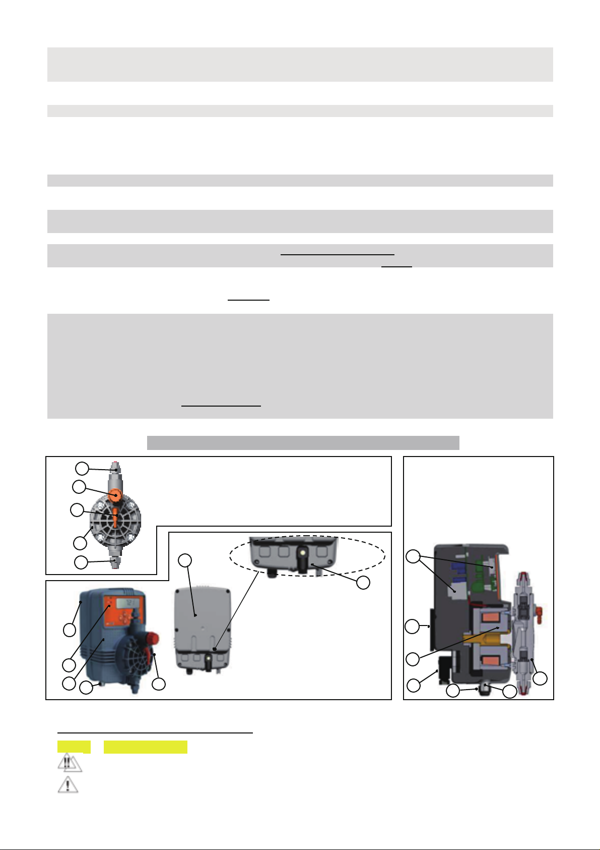
All EMAUX equipments are supplied fully assembled. Please refer to exploded view drawings shown in the
present booklet, showing all details and a complete overview of all components. These drawings are in any
case useful whenever spare parts are needed.
1.6.2 - DISMANTLEMENT
Before dismantling the unit or before carrying any operation, proceed as follows:
1. disconnect power.
2. relieve all pressure from discharge hose.

4
2.0 – CTRL - 2 SERIES DOSING PUMPS
2.1 – OPERATION PRINCIPLE
The dosing pump is activated by a PTFE diaphragm mounted onto a piston operated by pulses received from
the electromagnet. Return phase is spring operated. Control circuit is SMD (surface mounting device) with
microcontroller technology, digital controls, display and LED indicators for visualizing pump status. Operations
are simple, pump doesn’t need lubrication, and therefore maintenance is reduced almost to zero.
NOTE
CTRL2 is microcontroller based dosing pump which includes both a dosing pumps and high tech
controller which features two parameters all in one enclosure: PH or RX (ORP).
2.2 - CTRL - 2 SERIES COMMON FEATURES
The products are manufactured according regulation
Protection rating/ Housing:
IP65
/ Anti
-
acid plastic casing PP reinforced.
Control panel:
ensured by an adhesive polyester film, weatherproof an
d resisting to UV rays
Standard pow er supply:
fluctuations not to exceed ±10%: 230 V a.c.50 Hz si ngle phase
Optional pow er supply:
110 Vac / 240 Vac/ 50
-
60Hz/single phase
Ov ervoltage / Fuse:
category II.
MICRO
-
FUSE MT 1A
SLOW
Noise level:
65 ÷ 75 dBA
Ideal installation:
although IP65 rating, indoor or enclosed installati on use always
recommended.
Env ironmental Conditions:
possibly dry environment, altitude up to 2000m, ideal working temperature
5°C÷40°C. Relative humidity 80% for temperatures up to 31°C decreasing
linearly to 50% relative humidity at 40°C. Pollutio n degree 2.
Power cable:
3 m length
WITH
plug
Connections for level switch to activate level control for model
CTRL - 2
2.3 - LIQUID ENDS MATERIALS
PARTS IN CONTACT WITH LIQUID STANDARD VERSION UPON REQUEST
Pump head PP PVDF; PMMA
MEMO1 / NOTE
; AISI 316
Diaphragm
PTFE
------
Ball check valve
CERAMIC
AISI 316
Pump head Nipples / Hose
-
nut
PP
PVDF
; AISI 316
Seals / O
-
rings
FPM (Viton ) EPDM (Dutral ); NBR; SILICON
Injection Fitting
PP
PVDF
; AISI
316; PTFE
Injection No
-
Return Valve (sleeve)
FPM (Viton ) EPDM (Dutral ); NBR; SILICON
Foot “Lip” type check valve
FPM (Viton ) EPDM (Dutral ); NBR; SILICON
Filter body /
Filtering media
PP / GLASSWOOL
PVDF; AISI 316
Suction Hose
/
Air Bleed hose4x6mm
PVC flexible
PVDF; PTFE
Discharge Hose 4x6mm
PE semi- flexible
PVDF; PTFE
OTHER OPTIONS AND SPECIAL CONFIGURATIONS UPON REQUEST:
Reed type “Lip” Valve
FPM (Viton ) EPDM (Dutral ); NBR; SILICON
Hastelloy spring foo
t ball valve/
Fitting
HASTELLOY / CERAMIC/ PP-PVC
PVDF; AISI
316
Hastelloy spring injection valve/
Fitting
HASTELLOY / PYREX / PP-PVC
PVDF; AISI
316
Automatic auto-bleed pump head PVDF AUTO BLEED
NOTE
------
Aggressive chemicals configuration PVDF acid configuration
MEMO2
------
FPM=Viton / EPDM=Dutral : are registered trademarks of Dupont Elastomers
MEMO 1: polymer viscous liquid configuration PMMA pump head, Ceramic ball checks (Ø11), Fittings PP1/2”, seals FPM
or EPDM), Injection fitting and Strainer (without no- return valve), suction hose PVC flex.10x14, discharge hose PE 10x14.
MEMO 2: aggressive chemical configuration PVDF pump head/fittings, double Ceramic ball check valves, o-rings/seals
FPM (or EPDM or PTFE), Foot valve “LIP” type FPM, injection no-return Ceramicball check valves with hastelloy spring
return, suction / discharge hose PVDF
NOTE
Using AUTO-BLEED or Polymer PMMA configuration, pump pressure performance decreases of about 50%
PUMP
HEAD
TYPES
CTRL2
(Fig.1)
PP Standard
1 ÷ 15 l/h
PVDF Auto
-
bleed
1 ÷ 15 l/h
PVDF
1 ÷ 15 l/h
AISI 316L
1 ÷ 15 l/h
PMMA
1 ÷ 20 l/h
R
R
R
R
RR
R
R
R
R

5
2.4 - TECHNICAL CHARACTERISTICS
CTRL2 - 7L
Pump Max Flow / Max Pressure Start up*performance Frequency Stroke volume Pump head Valves
type range
l
/h
bar
l/h
bar
imp/min
cc(ml) / stroke
type
types
CTRL2 - 7L
CTRL2 - 5L
7 4
7
4
120
0,98
PP 3/8"
Ball chec
ks
CTRL2 - 5L
5 4 5 5
120
0,69
PP 3/8"
“Lip” types
Hose size:
4 x 6 mm
(available 6x8 fittings)
Max suction lift:
2 m
Power consumption:
Current consumption:
-
*NOTE
:
“Start up”
performances are available when the pump starts the operations and are constant onlyif duties are
not continuous (working for time periods not over 20/30 min and with at least 15 min rest).
2.5 – PERFORMANCE CURVES
3.0 – COMMISSIONING
CTRL2-7L series is provided with a quick mounting support bracket:
a. - Install the pump in a dry place, firmly to avoid vibrations, and well away from sources of heat and, in any
case, at environmental temperatures not exceeding 40°C. The minimum operating temperature depends on
the liquid to be pumped, bearing in mind that it must always remain in a liquid state.
b. - Fix the wall support brackets as shown in (fig.3).
Rear side to place
against wall or panel
Front side for sliding
pump rear slots
Mounting
bracket
side view
Fig.
3
Drill two holes an
d
insert dibbles then
scr
e
w
in bracket
Slide
pump
into slots
Performance curves (fig.2) are obtained testing the pump with water at room temperature and nominal suction height.
The above diagrams indicate max metering pump flow variation in relation to the working pressure in the plant; the
diagrams also include i.v.p. flow loss (injection valve pressure about 0,3÷0,4 bar).
REMINDER:
ratings vary with a tolerance of ±5% CTRL2-7L / ±10% CTRL2-5Lwhich must be taken into account when choosing
the pump typ: above diagrams show the performance and some of the curves have slight variation from nominal rating.
NOTE
when programming pump operations keep in mind that flow variation are related to the system pressure
variation; refer always to pump curves. Also consider that unexpected flow variations may occur for reasons not related
to pump functioning (viscosity, specificweight, sedimentation, etc).
bar
l/h
i.v.p.
0
10
15
5
7
4
5
10
15
2,5
-
15
1,5
-
10
5,5
-
07
07
-
04
dotted line =
Start-up curves
straight
line
=
Standard curves
CTRL2 7L performance curves
CTRL2 - 5L performance curves
bar
l/h
i.v.p.
0
10
5
5
10
6
4
2
07
-
02
0
5
-
0
4
2,5
-
06
0
1
-
05
Fig.
2
CTRL2 - 7L 37 watt CTRL2 - 5L 32 watt
CTRL2 - 7L
0,16 Amp
CTRL2 - 5L
0,14 Amp

6
c. - Carefully observe the regulations in force in the various countries as regards electrical installations (fig.4).
The pump is supplied with 3 m power cable without plug, the pump should be connected to mains supply
by means of a single-pole circuit breaker having a minimum distance of 3 mm between the contacts.
Before accessing any of the electrical parts, ENSURE that no electrical pow er supply is ON.
Operator must always protect itself w hen handling hazardous feed chemicals. Use goggles
And protective clothing and follow the safety information sheets of chemical manufacturer.
KEEP IN MIND: the unit works with voltage 230Vac +/-10% (within range 207÷253V). If the actual voltage is
constantly at the limit 10% and/or lower or higher and when voltage spikes are much higher then mentioned range,
fuse will blow and it must be replaced with one of same characteristics. We RECOMMEND the use of voltage
protections, check system ground and when connecting in parallel to other equipment use a “power switch”.
PARALLEL CONNECTIONS:
when the unit is connected to main power supply in parallel with other
inductive equipment (motors, pumps, blowers, solenoid and motorized valves), these gears must be
electrically isolated and well grounded to prevent damages from inductive voltages when switching ON / OFF.
- try to use a power switch in order to have separate connections via contact relay or relay.
- when this is not possible, contact EMAUX technical service.
d. Install the pump as shown in fig.4 bearing in mind that:
- ensure that max system pressure corre sponds to unit max pressure data (see performance curves).
- do not exceed the suction height over 2 m or as short as possible and vertical to prevent air pockets (fig.10)
- before connecting delivery hose to injection point, prime the pump following the sequence shown in fig.5,6,7.
- always use curved joints with suction or discharge hose. Try to keep both the suction and discharge hose as
straight as possible, avoiding all unnecessary bends.
- always use our standard strainer/foot valve provided with the pump, check clogging in case of solid particles.
- before finalizing connection of discharge hose, ensure that the pump strokes will not cause it to move from
installation or to touch external bodies.
Fig.5,6,7 the discharge nipple is always placed at the upper part of the pump head. The suction nipple (to
connect hose to foot valve / filter placed into chemical tank) is located at the lower part of the pump head.
CTRL2 DOSING PUMP PRIMING:
power the pump without sensor, wait for display to show initial measurings
and after few seconds for pulses to start; open pump head air bleed valve, as soon as liquid starts to move forward
into discharge hose, close bleed valve and stop the pump. In case pulses will not start, refer to page 18, paragraph
“13.1 – Dosing field direction menu”, change the direction dosing mode, move back to initial measuring display and
wait for pump pulses. Ensure during programming afterwords to select require dosing direction.
Fig.4
230
V
YELLOW
-
GREEN
w ire
BLUE w ire
BROWN
w ire
230 Vac
1 phase
Neutral
Power
cable gland
Fig.6
2.
Slide the hoses
over the nipples,
pushing them
toward the base
Fig.7
3.
Tighten hose
-
nut
using appropriate
force or by using a
wrench ensuring not
to break the nipple.
Fig.5
1
.
Remove the
RED protection
caps from two
pump head nipples
When
priming
the pump:
1. do not connect
discharge hose
to injection
point yet
2.
open Air bleed knob
turning it counter clockwise
3. Set press of frequency
range at 50% and stroke
adjustment (only FX series)
at about 80/100% of stroke
length, then push START,
4. suction of chemical from
dosing tank
5. once chemical will start to
be expelled from air bleed
hose returning to dosing
tank, press STOP Fig.8
6.
close Air
bleed
knob turning
clockwise
7.
connect discharge
hose to injection point
and begin dosing
operations

7
NOTE
In case of priming difficulties: use a normal syringe to suck liquid from the discharge nipple while the
pump is in operation (air bleed valve closed), continuing until you actually see the liquid rise in the syringe. Use a
short piece of suction hose to connect the syringe to the discharge nipple (refer parag.”TROUBLESHOOTING”).
3.1 - INJECTION VALVE INSTALLATION DIAGRAM
e. - Select the most appropriate injection point on the system pipe to be treated and fit a 3/8" female gas
threaded connection (BSPf): connection not supplied with the pump. Screw injection fitting into the
connection (fig.9). We recommend the use of a clamp-saddle for a clean installation.
- Although the injection fitting is provided with o-ring, we suggest increasing the sealing with PTFE tape.
- Connect discharge hose to the conical connector on the injection fitting and lock it with supplied hose-nut.
NOTE
The injection valve also acts as no-return valve by means of a cylinder sleeve (elastomer, standard
supplied in FPM “Viton”). Available also Hastelloy Spring return valve with ball checks. The “sleeve” D
must not be removed, performances will drastically change especially when operating at atmospheric
working pressure: flow rates will increase beyond performance curves (page 6).
3.2 - DOSING PUMPS TYPICAL INSTALLATIONS DIAGRAMS (fig.10, 11, 12)
- When operating at atmospheric pressure (no back-pressure) and additive chemical tank is located above
injection point (fig.11), injection valve condition should be checked at regular intervals because excessive
wear could cause additive to drip into the plant even when the pump is OFF. If the problem persists, install a
proper calibrated counter-pressure valve (C) between injection point and pump head discharge side.
- When dosing tank level and injection point are higher above the pump (fig.12), check hoses conditions.
- With chemicals generating vapours, don’t install the pump above the tank unless hermetically sealed.
NOTE
INSTALLATION NOTE FOR PVDF AUTOBLEED PUMP HEAD:
Auto-bleed pump head expels automatically air bubbles that are formed by the
chemical additive and are present into the suction tube thus during pump priming
there is no need for manual intervention. However, although this functions is
absolutely guaranteed, it’s always advisable to mount the pump with overflow
suction position (as shown in fig.13) just to prevent a sudden increase of air due to
mostly to temperature increase or when using a mixer.
4.0 – DISMANTLEMENT AND DISPOSAL
Commissioning, maintenance and repairs operations must be carried out by qualified personnel only
Operator must always protect itself when handling hazardous feed chemicals.
Fig.1
3
A
-
Process plant
B - 3/8" female steel gas thread connector
C - Cylinder sleeve (no return valve)
D - O-ring
E - Injection fitting
F - Conical fitting to connect discharge hose
G - Hose tube nut
H
-
Polyethylene discharge
hose
A
B
C
D
E
F
G
H
Fig.9
Fig.
10
TYPICAL INSTALLATION
delivery line
max 2 m
INSTALLATION WITH INJECTION POINT
LOWER THEN PUMP AND DOSING TANK
Fig.11
counter
-
pressure valve
(recommended)
INSTALLATION WITH INJECTION
POINT HIGHER THEN DOSING
TANK
Fig.12

8
CAUTION before carrying out any serv ice on the pump: pump must be accessible at all times for
operation and service. Access must be free and without obstacles.
- Disconnect pump from the mains or from switch contact switch.
- Relieve all the pressure from the pump head and all liquid ends.
- Drain or flush all dosing liquid from pump head. This operation can also be executed by disconnecting the
pump from the plant by turning the pump upside-down for 15 to 30 seconds without connecting the tubing to
the nipples; if this operation is not possible, dismount and remount the pump head using the four mounting
screws. In the event of possible liquid ends leakage (wearing out or damage of "O" ring seals, valves or
hoses) the pump should immediately be brought to a stop, emptying and depressurising the discharge hose
while taking all due safety precautions (gloves, goggles, overalls, etc.).
- Whenever the pump is dismantled from installation, place back the RED protection caps on the nipples to
avoid residual liquid being spilled.
- When dismantling a pump, clean the pump and liqui d ends removing all chemical additive residuals present
on the housing and inside hydraulic components.
- For disposing a unit, follow local authorities rules for disposing of equipments and chemical products; send
parts to authorized recycling centers for correct disposal. DO NOT POLLUTE THE EARTH !!!!
REMINDER
: during maintenance operation bear in mind that discharge and suction valves are mounted in
different position according to function.
5.0 – MAINTENANCE
1. Periodically check chemical additive tank level so as to avoid the pump operates without liquid. This would
not damage the pump, but may damage the process plant due to lack of chemical. FX series dosing pumps
are all supplied with level control setting. The level switch is not included therefore to be ordered separately.
Level control stops pump operation once chemical level into the tank is lower than level switch, thus activating
a L.E.D. on the pump
2. Check the pump operating conditions at least every 6 months:
- pump head position, screws, bolts and seals;
- check more frequently where aggressive chemicals are pumped, especially:
- If a reduction of the required additive concentration in the process plant is detected, this could be caused the
reduction of the dosing pump flow rate by valves wearing, in which case they need to be replaced or by the
clogging of the filter which has to be cleaned as i n fig.13 here below.
3. The Company suggests periodically cleaning hydrauli c parts (valves and filter). We cannot say how often
this cleaning should be done as it depends on the type of application, we also cannot suggest what cleaning
agent to use as this will depend on the additive used.
Operating suggestions when dosing sodium hypochlori te (most frequent case):
a
-
Disconnect the pins from the mains or from power switch;
b
-
disconnect discharge hose from process plant;
c
-
remove the suction hose (with filter) fro
m the tank and dip it into clean water;
switch ON the dosing pump and let it
operate with water for 5 to 10 minutes;
d
-
switch OFF the pump, dip the filter into a
hydrochloric acid solution and wait until end
of cleaning;
e
-
switch ON the pump again and operate it
with hydrochloric acid for 5 minutes in a
closed-circuit, with suction and discharge
hose dipped into the same tank (fig.14);
f
-
repeat the operation with water;
g
-
re
-
connect hoses to dosing pump and
injection valve to the process plant;
h
-
re
-
tighten liquid end screws after 24 hours
in operation, and then after 3 months.
Operator must always protect itself when handling hazardous feed chemicals.
5.1 - HOW TO OPERATE WHEN DOSING SULPHURIC ACID
In case of dosing Sulphuric Acid up to 96% or other aggressive chemicals, bear in mind the following:
1. replace PVC suction hose with polyethylene discharge hose;
2. empty any residual water from the pump head beforehand.
Warning: if water mixes with sulphuric acid it can produce a large quantity of gas with consequent
overheating of the area causing damage to valves and pump head. This operation can also be done with the
pump disconnected from the plant by turning the pump upside-down for 15 to 30 seconds and without
connecting the hose to the nipples; if it’s not possible, unscrew the pump head, empty it and then remount it.
EMAUX provides a special liquid ends configuration for Sulphuric Acid or other aggressive chemicals.
Fig.14
Foot valve / filter
Injection valve
CLOSED
WATER LOOP
Pump head cleaning
Fresh water bucket

9
6.0 – WIRING SERVICE CONNECTORS FOR CTRL2
(fig.15)
Always TURN PUMP OFF when servicing and wiringconnectors !!!
FEMALE SERVICE CONNECTOR WIRING DIAGRAM Functions descriptions
CONNECTOR 1
CONNECTOR 1
Lev el switch connection (fig.15)
Configurations
Pin 1 = NO connection
Pin 2 = NO connection
Pin 3 = Level switch wire
Pin 4 = Level switch wire
PUMP LOWER SIDE
- Power cable clamp
- pH or RX electrode
once wiring is completed there will be no accessible contacts
OVERALL DIMENSIONS
Approximate
net weight
kg 2.0÷2.5
Lev el switch
3
4
2
1
1
Fig.
16
Fig.1
5

10
CTRL2
7.0 – DUAL PARAMETER DOSING PUMP AND PHRX CONTROLLER CTRL2
This unit is microcontroller based dosing pump incl udes both a dosing pumps and high tech controllers which
features three parameters all in one enclosure: PH or RX (ORP).
BENEFITS: reducing stock value against a great quality and versatility
7.1 - CTRL2 DIGITAL CONTROLS (fig.17)
1
-
Enter button “OK”: confirms selection
2
-
Increasing value button
3
-
Decreasing values button
4
-
"YELLOW" LED: level alarm / over dosing alarm / malfunction alarm
5
-
"RED" LED injection pulse flashi
ng
6
-
Power “GREEN” LED: pump is feed by mains power supply
7
-
LCD display
8
-
ESC escape button
7.2 - CTRL2 CONTROLLER MAIN FEATURES
pH:
measuring range 0÷14,00 pH (resolution 0,01pH)
RX:
measuring range:
-
1000÷ +1400 mV (resolution
1mV)
•2 Reset modes: full reset - partial reset keeping calibration settings
•Proportional mode: selection of proportional range value
•Delay adjustment - Delay at powering ON (electrodespolarization)
•Stand-by for cleaning electrodes and sensors or re-calibration
7.3 - LEVEL CONTROL ONLY CTRL2/L (fig.18)
The pump is supplied with level control setting and upon request floating level switch.
When the level of the additive is lower than the switch, level alarm and yellow led are
ON: the pump is OFF. The level control alarm goes ON within 5 seconds delay.
Floating Level Switch Joint level sw itch / filter
NOTE: when using a mixer in dosing tank this will cause turbulence, ensure that
floating switch is connected to filter fitting to avoid floating switch incorrect operations.
7.4 - ACCESSORIES (fig.19)
•1 semi-rigid Polyethylene hose 4x6 mm, white, 2 m;
•1 flexible PVC suction / air bleed hose, 4x6 mm, transparent, 2+1,5m;
•1 injection valve 3/8 BSP m;
•1 foot valve / filter;
•3 m power cable (three wires) with plug;
•mounting screws and dibbles, instruction booklet;
•level switch in case of CTRL2/L model
6
5
4
3
Fig.1
7
2
8
7
1
Fig.18
Fig.19

11
8.0 – DISPLAY DESCRIPTION
OVER
Overdosing alarm
SETUP
Unit general settings
DELAY
Del
ayafter switching unit ON
STARTUP
Switching
-
on delay settings
SET POINT
Set
-
point programming
RESET
Reset activation
LEVEL
Level alarm
DIRECTION
Intervention field selection
ALARM
Alarmslevel setting
MAX**
Max Impulse / minute (frequency)
MENU
Menu selection Basic/Full
h:m:s
Hours:minutes:seconds
ON-OFF
ON
-
OFF operating mode
°C
Temperature
°C
PROP.
Proportional functioning mode
°F
Temperature
°F
HYST.
Hysteresis
programming
%
Flow rate percentage
1 2
C
alibration points
H
pH measuremen
t
CALIB.
Calibration menu
mV Rx
mV (Rx) measurement
Intervention Alkaline / Oxidant / Direct
Intervention Acid / Reduction / Inverse
min
pulses / minute
* Flow sensor = Proximityswitch
** Maximum pulses frequency based to maximum measuring value
9,0
–
PARAMETERS AND FUNCTIONS (pH default)
DEFAULT
Set-point setting 7,2
Hysteresis setting 0,1
Choice of intervention of dosing field (acid / alkaline) Acid
Selection ON-OFFmode or proportional mode Manual
Definition of proportional intervention value "AUTO" selection + 1pHSet point
First point of calibration procedure -------
Second point of calibration procedure -------
Minimum alarm point 0,00
Maximum alarm point 14,00
Over-dosing time alarm value 99:59 h:m
Parameter measuring selection (PH or RX) pH
Temperature system selection (°C or °F) °C
Temperature compensation selection (manual - auto) Manual -25°C
Delay relayoperations when switching pump ON 00:03 m:s
Selecting time delay to exit programming 05:00 m:s
PARAMETER TYPICAL CHARACTERISTICS VALUE
Environmental temperature range 0÷40°C
Max current relay output 6A (resistive load)–1A(inductive load)
pH measurement 0÷14°C (resolution 0,01 pH)
RX (mV)measurement –1000 ÷ +1000 (resolution 1 mV)

12
10.0
–
PROGRAMMING
CONTROLLER
KEEP IN MIND:
if no selection is made dusring set-up step, pumpwil start to release pulse strokes
10.1
–
PUMP SETUP / CONTROLLER SETTING
The first operation is to select the required parameterintended to measure and control pHor RX (mV).
Pump power ON, display will show last software revision and also the
type of measurement parameter flashing (default setting: pH with
operating menu BASE basic-simplified mode).
Now it is possible to select required measuring parameter, pH or
RX, by means of –or + buttons and press OK to confirm.
Select type of measuring parameter and confirm OK, programming
movesto measuring mode, displaywill show current measured value.
PressOK to entermenus; it will show SETPOINTmenu,
using –or +buttons to scroll all 4 menus.
Set point menu
Calibration menu
Alarm menu
Set up menu
-
this symbol “pointing finger” indicates
programming steps “PRESS”.
NOTE
Afterabout 2 seconds, selection isoperational and operatorcan decide whetherto quitSETUP menu orto
continue for additional settings. In view of selecting pH, Redox measuring, check next paragraph.
To enter SETUP menu, display will flash SETUP
scroll with +or –buttons and once reached required menu
press OK to confirm
Afterabout 2 seconds, selection is operational and operator can
decide whether to quit SETUP menu or to continue for additional
settings. In viewof selecting pH, Redoxmeasuring, check next
paragraph.

13
10.
1
–
MEASUREMENTTYPE SEL
ECTION
Once entered SETUP menu it’s possible to select the required type of
measurement parameter. Default is to pH
Pressing –and + buttons a loop menu isentered , user can select
among 2 measurementsparameters: pH or RX (mV).
To confirm selection pressOK
The program will enter Password menu.
pH flashing, display visualises pH value not to be
considered since calibration isyet to be completed
To select OK
Moving to SETPOINTmenu
mV RX flashing, display visualisesa RX value not
to be considered since calibration is yet to be completed
To select OK
Moving to SETPOINTmenu
10.
2
–
TEMPERATURE: SELECTI
ON CELSIUS OR FAHREN
HEIT
Press OK, select temperature reading eitherin Celsiusdegrees or Fahrenheit degrees(°C or °F).
To shift use –or + PressOK to confirm selection
OR
10.
3
–
TEMPERATURE COMPENSA
TION
The pump allowsto select manual temperature compensation, that is setting the temperature at the same
value of the system to be treated and such value will remain constant
.
Also it’spossible to switch from C°(celsiusdefault) to F°Fahrenheit.
To select manual temperature compensation display will flash OFF
pressing OKdisplay will flash default temperature 25.0 °C.
Using +or –buttons it ispossible to change thisvalue. When the
desired value is reached press OK to memorize and move on.
10.
4
–
DELAY OF DOSING OPER
ATION AFTER SWITCHIN
G “ON” THE UNIT
Due to electrodestime polarization inertia or plant installation characteristicsor previousprogramming data, the
pump has the possibilityto set a delay from the time the pump isswitched ON to the concrete measuring, control
and dosing operations. It will start measuring operation after3 seconds (default) from switch ON.
It’sa safety measure to ensure a correct electrode reading before activating the dosing pump.
Using –or +
it'spossible to set delay time, from 0 to 99 min.59 sec.
To shift from minutes to second press Right arrow
PressOK to confirm

14
11.0
–
CALIBRATION
To calibrate controller,user must adjust two calibration points:
for pH two adjustable point
for Redox (mV) one adjustable point
1
1
.
1
–
CALIBRATION MENU
To enter CALIBRATION menu from measuring mode
press OK then +button, on display CALIB. will flash
press again OK to confirm
Display will show POINT1 and default7,20
pH CALIBRATION PROCEDURE
• Dip pHelectrode into buffer solution pH7.00
• Adjust value on display using –or + until reaching 7.00
Wash electrode with tap waterbefore dipping into second solution.
PressOK to confirm. Display now will show POINT2.
• Dip pHelectrode, in the second buffer solution ( pH9.00 orpH 4.00,
use fresh solution always).
• Adjust value on display using –or + until reaching 9.00 or 4.00.
PressOK to confirm
REDOX (mV) CALIBRATION PROCEDURE
• Short circuit BNC connector. Using a metal wire (eg: screwdriver),
connect the pin core with the external element of BNC.
Using –or +adjust value on display to reach 0
PressOK to confirm. Display will show POINT2
• Dip RX electrode into buffer solution (475 or250 or650mV).
Using –or +adjust until display showsthe buffer solution value.
PressOK to confirm.
BNC CONNECTOR
12
.
0
–
PROGRAMMING
SET
POINT
NOTE
To have the pump operative it's mandatory to set the following data: Set-point values, type of dosing
“DIRECTION” meaning (for example for pH measurement acid or alkaline operation, for RX reduction or oxidant),
hysteresis setting, manual (ON-OFF) or proportional dosing.
There are two different Set point setting procedures according to the operating menu of the pump: BASE or FULL.
NOTE
FULL menu is functional only if it has been selecte; a pump with FULL menu features extra output
connectors but only with CTRL3a version. Let's start with BASE menu activated (paragraph 10.1),but KEEP IN
MIND that the same procedure is valid also for FULL version menu.
12.1 – PROGRAMMING PH SET-POINT
From measuring status,
press OK, the program will move to SETPOINTprogramming.
Press OK again, display will show 7,20 pH flashing meaning
that it can be adjusted to required set point
Using –or + buttons.
Once selected required set point, press OK to confirm.
The pump automatically will move to DOSING DIRECTION menu.

15
12.2 – PROGRAMMING REDOX SET-POINT
From measuring status,
press OK, the program will move to SETPOINTprogramming.
Press OK again, display will show 650 mV flashing meaning
that it can be adjusted to required set point.
Using –or + buttons.
Once selected required set point, press OK to confirm.
The pump automatically will move to DOSING DIRECTION menu.
13
.
0
–
SET
POINT
SET
TINGS
13.1
–
DOSING FIELD DIRECTI
ON MENU
This menu selects the dosing field direction of dosing pump (above the setpoint or below this value) according to
water acid or alkalin characteristics: to reduce pH value acid must be dosed, direction arrow must point down.
Thisway dosing pump will be active when pH value ishigher than the setpoint previously set.
Viceversa, to increase pH value alkaline chemical must be dosed. This way dosing pump will be active when pH
value is higher than required set-point.
Same procedure for RX and Chlorine measurements: if pump hasto reach a certain quantity of oxidant or chlorine,
the direction arrow has to point aloft, vice versa, for a reducent
chemical.
From measuring status,
To select arrow direction, press –and +
Press OK to confirm.
13.2
–
MANUAL ON
-
OFF DOSING MODE / PR
OPORTIONAL DOSING MO
DE MENU
ABOUT DOSING MODES
ON-OFF : dosing pump will operate with ON-OFF mode and with flow rate selected by the user at max
frequency (chapter 11.5)and will stop once reached required set-point.
PROP : with this mode the pump will dose proportionally to the current measured value and its distance to
selected set-point. The pump starts dosing over set-point (determined by hysteresis), at MAX FREQUENCY
selected after pressing OK fromthis menu. Then injectionsfrequencywill decrease proportionally until stopping
once reached set
-
point value.
After selected “direction”, display will show ON-OFF flashing
With – and + it'spossible to shift to PROP
PressOK to confirm the selection.
Herefollowing will be described flow rate adjustment setting.
WHAT’S THE HYSTERESIS ? Hysteresis function is featured when working with ON-OFF mode: it’s useful when
there are to many or quick changes around set point value which could damage dosing pump. Increasing
Hysteresis value will activate outputsonlywhen measured value moves away fromset point according the required
value. Example: if required and selected pH set-point is 7.2 and hysteresisis set at 0,1, in case of measurement
changes fromselected set point, dosing output operations will be activated at 7,1 or 7,3 pH.
13
.
3
–
HYSTERESIS SETTING
Once selected direction of dosing (paragraph 11.1.1), adjust
hysteresis value, meaning the distance from selected Set-point, over
this value the pump will start or stop dosing operations
Pressing OK to enter Hysteresis menu setting
Press –or +to select required hysteresis value (default 0.05 pH)
Press OK to confirm

16
13.
4
–
FLOW RATE FREQUENCY
ADJUSTMENT
–
MAN (MANUAL ON
-
OFF) SETTING
Selecting Manual mode (ON-OFF), pressing OK, program will move to Frequencyadjustment setting.
User must set dosing pump flow rate selecting strokesfrequency range from 0 to 100%.
Max frequency120 imp/min.
Use +or – to select strokes frequency percentage equivalent to
required flow rate.
PressOK to confirm and exit Setpoint menu.
Press ESC to return to measuring mode.
13.5
–
MAX FREQUENCY ADJUST
MENT
-
PROPORTIONAL DOSING
MODE SETTING
Selecting Proportional mode (PROP.), after pressing OK, pump will move to Max frequency adjustment menu.
Select at which pH, Redox or Chlorine measuring value dosing pump will operate at max strokes(injections)
frequency. From thispoint pump will decrease injection proportionally while getting close to set-point until stopping
once isreached. Follow these three STEPS.
STEP 1
With – and + select maximum
measured value to correspond
dosing pump maximum injection
frequency. Press OK to confirm and
move to Step 2.
STEP 2
Ensure displayshow max injection
frequency100% (120 imp/min).
STEP 3
With – and + select minimum
measured value to correspond
dosing pump minimum injection
frequency. Press OK to confirm
and exit Set-point menu.
Press ESC to return to measuring mode.
15
.
0
–
ALARM
SETTINGS
1
5
.1
–
ALLARM SETTINGS
It ispossible to plan three different typesof alarm settings:
1 - MAX ALARM point: user can select maximum value ALARM point (pH or mV or ppm) where the unit will enter
Alarm mode. When measuring value will go over selected point, display will show ALARM flashing and Alarm
LED flashing.
2 - minimum ALARM point: user can select minimum value ALARM point (pH or mV or ppm) where the unit will
enter Alarm mode. When measuring value will go lower thispoint, display will show min and ALARM flashing
and Alarm LED flashing.
3 - OVER ALARM TIME: In case problems may occur in the system and/or the unit (wrong calibration, dirty or
broken sensors, etc.) to avoid overdosing of chemical, user can select OVER ALARM TIME in which the pump
must reach Set-point, passed the selected time, pump will stop dosing operations.
Display will show ALARM flashing and Alarm LED flashing.
To enterin ALARM menu followthe procedure described in
paragraph10.1 “PUMP SET UP / CONTROLLER SETTING” , when
ALARM menu isreached, press OK to enter submenus.

17
15.1.1
–
MAXIMUM ALARM SETTING
Display shows
MAX and current measured value both flashing.
Press– or + to select max measured value ALARM point
PressOK to confirm
15.1.2 – MINIMUM ALARM SETTING
Display shows
min and current measured value both flashing.
Press– or + to select minmeasured value ALARM point
PressOK to confirm
15.1.3 – ALARM SETTING
Display shows OVER DELAY and time counter h:min flashes.
Press – or + to select Over Dosing time, passed thispoint
pump will enter alarm mode and stop dosing operations.
PressOK to confirm
PressESC to return measuring mode
16
.
0
–
RESET / STAND
-
BY
16
.
1
–
RESET PROCEDURE
Here following are stepsfor RESETprocedure:
• Switch OFF and ONthe unit
Pressat the same time ESCand OK until display will show
the latest firmware revision (e.g.02.3.3), then will appear
SET UP and default parameterswill blink.
Now user has15 secondsto complete reset operation.
press together
After15 seconds fromentering SETPOINTmenu, it’ NOT possible to activate reset procedure. Therefore the
userhasto switch unitOFFand then ONagain to start reset procedure.
16
.
2
–
STAND
-
BY PROCEDURE
The unit can be placed in STAND-BY mode to allow sensors and
accessories maintenance operations.
Pressand hold +and – at the same time until display will
showSTAND-BY STBY flashing
• To exit Stand-By mode
Press and hold +and – buttons at the same time until
display will show previousmeasuring settings.
press together
TO EXIT
press together

18
17.0 – TROUBLE-SHOOTING FOR CTRL2 SERIES
Operator mustalways protect itselfwhen handling hazardous feed chemicals. Use googles and
protective clothing and follow the safety information sheets of chemical manufacturer.
When removing the metering pump from the plant, be careful as there might be some residual
additive in the discharge hose.
- Due to robust design the pump isquite robust therefore there are no apparent mechanical problems.
- In case of leakage from nipples, checktube nut tight setting.
- Diaphragm rarelybreaks (made of pure PTFE synthesized),however check diaphragm-pump head o-ring.
- Occasionally there might be a loss of liquid from the nipple because the tube nut has loosened, or more
simply the discharge hose has broken. Very rarely there may be losses caused by the breakage of the
membrane, or by the membrane seals in which case they have to be replaced by disassembling the four
screws of the pump head, when re-mounting the pump head ensure that the screws are replaced properly,
properly, along with “O” ring.
- re-tighten liquid end screwsafter 24 hoursin operation.
- After repair,metering pump will need to be cleaned of additive residueswhich can damage pump casing.
TROUBLE-SHOOTING QUICK VIEW
PROBLEM CAUSE ACTION TO TAKE:
1
⇒GREENLED LIT
AND RED LED
FLASHING, DOSING
PUMP PULSES BUT
ADDITIVE IS NOT
INJECTED
cause 1:diaphragm rupture and/or
pump head o-ring isnot sealing
because worn out or not compatible
with liquid.
a. Dismount the suction and discharge
valves, clean them reinstall them or replace
(pump head viewsin the following pages). In
case of using LIP type valves and should the
valves be swollen, check valves material
against our chemical resistance compatibility
chart and fit correct valves.
b. Check clogging of the filter
c. Checkinjection valve condition
d. Check systempressure
cause 2: chemical can produce
crystalline depositsin the hydraulic
partsor clogging the filter.
2
⇒GREENLED LIT
AND RED LED
FLASHING, PUMP
PULSES BUTPUMP
IS NOTPRIMING (NO
LIQUID SUCKED)
a. Dismount the suction and discharge valves, clean themand replace,see position
(fig.10)and follow the same point as above point 1.
b. In case of priming difficulties: use a normal syringe to suck liquid fromthe
discharge nipple while the pump is in operation (airbleed valve closed), continuing
until you actually see the liquid rise in the syringe. Use a short piece of suction PVC
hose to connect the syringe to the discharge nipple (see photo sequence below)
cause2: fuse blown or defective. Also a
possible voltage spike higher then pump
range has blown fuse or damaged pcb.
Disconnect the pump from power supply, check the
fuse and if blown or defective change it with same
type or contact manu facturer Customer Service,
Dealeror Distributor. CTRL2 series are equipped
with a MICROFUSE MT 1A slow.
DO NOT REPLACE FUSE WITH OTHER TYPES: it will severely damage pump and other equipment !!!
In case of severe and continuous voltage fluctuation, the fuse could blow continuously. In this case contact
manufacturer Customer Service, Dealer or Distributor for a correct solution.
Insert syringe hose in
place of discharge hose
ensuring that the same
is NOT connected to
injection valve.
Close pump head air bleed valve.
Startpump pulses above 50% rate and start sucking with
syringe until the liquid start to come up costantly in syringe
hose then stop the pump and take out syringe hose.
Reinsert discharge
hose ensuring that the
same is connected to
injection valve and
start the pump.
3
⇒ALL LED
DISPLAYS ARE OFF,
THE PUMP DOES
NOT PULSE
cause 1:power supply cable not
plugged or wrong power supplyor
plug not wired correctly.
Check power supply (socket, plug, power
switch ON), if the pump doesn’t work contact
manufacturer Customer Service, Dealer or
Distributor. Ensure systemis well grounded,

19
…MORE TROUBLE-SHOOTING QUICK VIEW
PROBLEM
CAUSE
ACTION TO TAKE:
4
⇒GREEN LEDIS ON, REDLED (PULSE)IS OFF, THE
PUMP DOES NOTPULSE
SOLENOIDDATATO CHECKWITHTESTER
CTRL2-7L types 1,5-10 / 2,5-15 / 5,5-07 / 07-04:
Ω230
CTRL2-5L types 01-05 / 2,5-06 / 05-04 / 07-02
Ω275
Disconnect the pump from power supply,
open dosing pump and disconnect solenoid
wires from pcb and, with a tester, measure
electrical resistance (check solenoid view
page 23) then contact manufacturer
Customer Service, Dealer or Distributor.
5
⇒PUMP PULSES ARE NOTCONSTANT
Check that voltage iswithin +/
-
10
-
15% of
rated voltage
6
⇒DOSING PUMP GIVES ONLY ONE PULSE
Disconnect the equipment and contact
manufacturer Customer Service, Dealer or
Distributor.
7
⇒DOSING PUMP
PULSES WORKING
NORMALLY, ALL
LEDS ON, BUT FLOW
RATE IS MUCHLESS
THEN EXPECTED
cause 1:
pumped additive
isvery viscousor with high
specific weight
a.
Check liquid viscousity and if it’s higher then 500
cps change standard pump head with PMMA type
(viscousconfiguration)
b. If it’s not higher then 200 cps, using same pump
head, select higher performance dosing pump (at
least double flow rate of the one requested
cause 2:
solenoid not
working properly
Disconnect power supply, open dosing
pump and
disconnect solenoid wires frompcb and, with a tester,
measure electrical resistance then contact
manufacturer Customer Service, Dealer or Distributor.
8
⇒LIQUIDIS
LEAKING
- from back ofthe
pump head:
cause 1:
diaphragm
-
pump
head o-ring is not sealing
because worned out or
faultydue to not
compatible with liquid.
Check diaphragm
-
pump head o
-
ring and replace it
with new one or compatible one.
cause 2:
pump head
screws are not well tighten.
Tighten firmly pump head screws.
9
⇒LEAKAGE
- from the pump head
nipples:
cause 1:
nipple o
-
ring is
not sealing because worn
out or faulty because not
compatible with liquid.
Check nipple o
-
ring and replace it with new one or
properone compatible.
cause 2:
hose isnot
locked tight with tube nut.
Tighten tube nut on hose.
10
⇒HOSE
BREAKING
Hosesare breaking
(mostly discharge one)and
liquid iscoming out
a.
Ensure hose
-
nuts on the nipple (mostly discharge
side) are NOT over-tighten
b. ensure that hoses are straight, without angles
c. check chemical compatibility
11
⇒FOR
CTRL
2
/L
ONLY
FLOATING LEVEL SWITCH NOT WORKING
a.
Check that the connector male/female between
level probe and pump is securely fastened.
b. If problem persists make a short connection
between pin #3 and pin #4 with a wire or small pliers.
In case the level alarm LED turns ON, replace level
probe. If problempersists, contact distributor.
12
⇒IN CASE ADDITIVE LEVELIS BELOW THE
LEVEL PROBE AND LEVELALARM IS STILL OFF
Check the level switch connection as previouspoint
b.,
in case the level switch isworking and the level alarm
LEDis still OFF, contact manufacturer customer
service, dealeror distributor

20
18.0 – ELECTRODE CLEANING AND MAINTENANCE
The formation of depositson the electrode will produce erroneousreadings. The necessary cleaning action
depends on the type of deposit under consideration. In case of thin deposits, shake the electrode or use a
spray of distilled water. Organic residues or particularly resistant deposits should be removed by chemical
means. Mechanical cleaning of the bulb should be resorted to only in extreme cases, but bear in mind that
abrasion can lead to irreparable damage. If cleaning doesnot fully re-establish the efficacy of the electrode, it
may be that the electrode hasaged. Ageing will show itself in the for of either a measurement error or a slow
response. RECONDITIONING
The following chemical treatmentsmay be carried out with a view to reconditioning the electrode. We list them
in order of increasing aggressiveness asfar asthe bulb is concerned and would ask you to note that they will
not necessarily improve the electrode quality, which in some cases mayeven be further reduced.
1) Immerse the tip of the electrode in 0.1N hydrochloric acid (HCl) for 15 seconds, then rinse with water and
dip again the electrode in a 0.1N solution of sodium hydroxide (NaOH) for 15 seconds, followed by a second
rinsing. Repeat this sequence three times, and then carry out another check measurement. If the reading
remains erroneous, proceed to treatment 2.
2) Immerse the tip of the electrode in a 20% solution of ammonium bifluoride (NH2F-HF) for two or three
minutes, then rinse with water and make another checkmeasurement. If the reading is still unacceptable,
proceed to treatment 3.
3) Immerse the tip of the electrode in 5% hydrofluoricacid (HF) for 10 seconds, then rinse thoroughly in water
and very quickly in 5Nhydrochloricacid (HCl), followed by a second rinsing in water. If the check
measurement still producesunacceptable measurements, it only remains to change the electrode.
17.1 - ELECTRODE HOLDERS
Different types of electrode holders are available: for immersion, electrode cell, and in-line. It is essential to
bear in mind that the distance between the injection point and the electrode must never be less than one
meter. When thisisnot possible, an appropriate chemical mixer must be inserted between the injection point
and the electrode.
EMAUX EL ECTRODE HOL DERS FOR CTRL2-7L APPLICATIONS
ECELL1
ECELL 4
ELINE1 / ELINE1-A ELINE2 ESUB
Part no.
Model
SPS0000901
ECELL1:
Off
-
line holder 1 electrode, earth
,
external valve for incoming flow control
SP
S0001201
ECELL4:
Off
-
line electrode and temperature probe holder, with Proximity switch
2143002
ESUB 0,5 m
submersible holder, PVC body, length 50 cm
2143003 / 2143004
ESUB 1 m / 1,5 m:
submersible holder, PVC body, length 100 cm / 150 cm
2143001
ELIN
E1 (PVC)
In
-
line holder, PVC
, pg3,5 1/2”
DPS0001601
ELINE1
-
A (AISI)
In
-
line holder, AISI 316L, pg3,5 1/2”
1PRS005
ELINE2 (PP)
In
-
line holder, pg3,5 1/2”
This manual suits for next models
1
Table of contents
Other emaux Water Pump manuals

emaux
emaux FSF Series User manual

emaux
emaux SS Series User manual

emaux
emaux AFS40 User manual

emaux
emaux FSP300-4W User manual

emaux
emaux SPV Series User manual

emaux
emaux FSU-4TP User manual

emaux
emaux SPV Series User manual

emaux
emaux APS Series User manual

emaux
emaux UPH Series User manual

emaux
emaux SPV150 User manual
Popular Water Pump manuals by other brands

Pfeiffer Vacuum
Pfeiffer Vacuum ATH 3200 MT operating instructions

Gardena
Gardena 10000 SL Inox operating instructions

Berkeley
Berkeley S.A.E. Installation, Repair, and Operating Instructions

Mega
Mega M4B owner's manual

Grundfos
Grundfos UPM3 Installation and operation manual

Muncie
Muncie ACM-302 installation instructions