420X297(mm) 80g印尼蓝
双面印刷
2016.09
1 : 1
PANTONE Process Black C
材料
工 艺
日 期
EMAUX FSF500(650)-6W+SC (220V 60Hz) 缸连泵 英文说明书
EMFS16100503
名 称
版 本 编 号
规 格
比 例
颜 色
产品负责人
更改日期
更改内容
版本 制图/设计
A
意万仕(中山)泳池设备有限公司
EMAUX ZhongShan)Swimming Pool Equipment Co., Ltd(
审核 批准
INSTALLATION
WARNING
By-passes filter for circulating water to pool
Used after backwash to flush dirt from valve
Cleaning Filter by reversing the flow
By-passes filter, used for vacuuming to waste or lowering water level
CLOSED Shuts off all flow to filter or pool
RECIRCULATE
WASTE
RINSE
BACKWASH
FILTER
Valve Position Normal Filtration and Vacuuming
Function
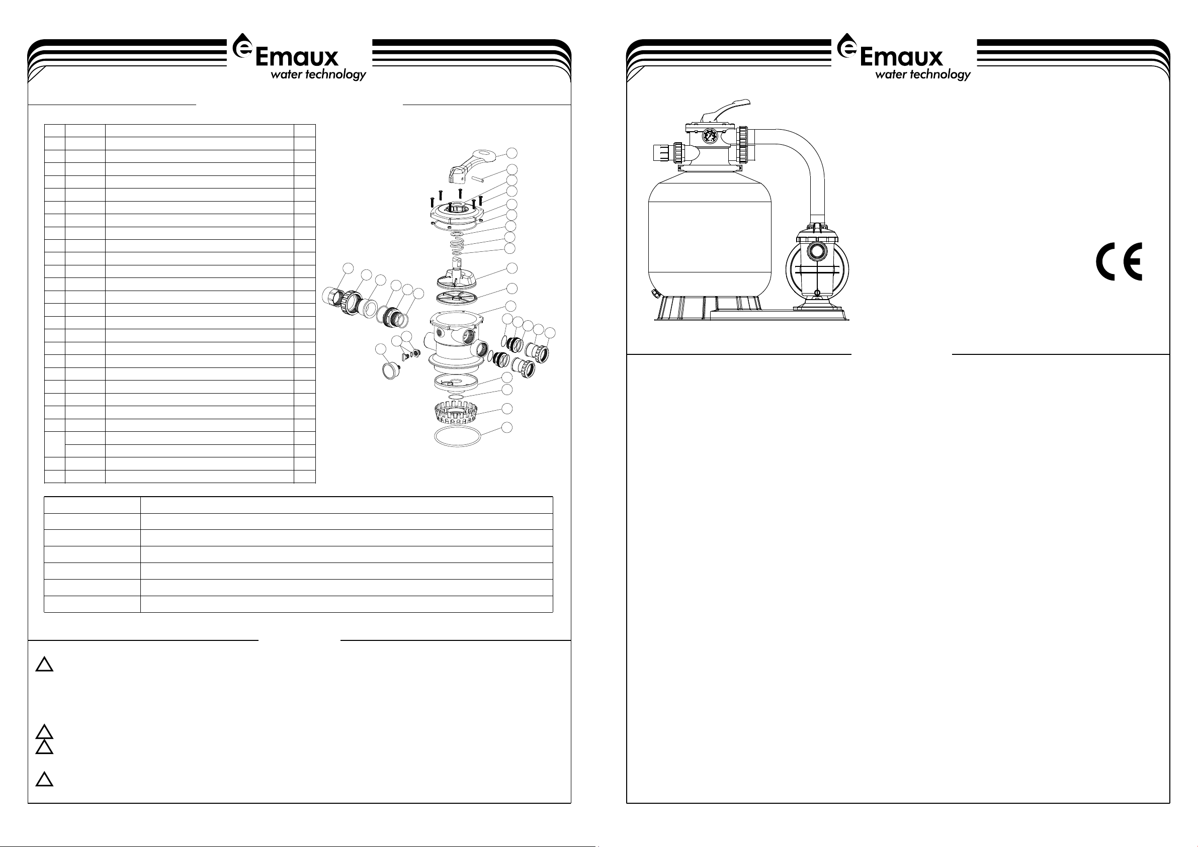
VALVE REPLACEMENT PARTS
FILTER & PUMP COMBO
Installation & Operating Instruction
FSF500-6W / FSF650-6W
1-4
4-4
17
18
19
20
21
13
14
15
16
6
12
1
2
3
4
5
7
8
9
10
11
17
18
19
22
21
23
24
25
26
* Install filtration system including pump,filter tank and multiport valve.
* The filter system should be installed as close as possibie to the swimming pool and preferably at a
level of 0.50 metres below the surface of the water in the swimming pool. Make sure there is
drainage available at the place where the filter is to be installed.
* PUMP
1)Onlyqualified,licensedpersonnelshouldinstallpumpandwiring.
2) Electrical Contractors Please Note:All 220 volt 60Hz pump must be wired to the main power supply
troughanapprovedandcorrectlyratedcontractor.
3)Allowforgatevalveinsuctionpiping.
4) Pump suction and discharge connections have moulded in thread stops,do not try to screw pipe in
beyondthesestops.
* FILTERTANKandMULTIPORTVALVE
1)Loadingthesandmedia.Filtersandmediaisloadedthroughthetopopeningofthefilter.
a)Loosentheplasticclampsfromtankneck.
b)Capinternalpipewithplasticcaptopreventsandfromenteringit.
c) We recommend filling tank approximately 1/2 way with water to provide a cushion effect when the
filtersandispouredin.Thishelpsprotecttheunder-drainlateralsfromexcessiveshock.
d) Carefully pour in correct amount and grade of filter sand.Be sure center pipe remains centered in
opening. Sand surface should be leveled and should come to about the middle of the filter
tank.Removeplasticcapfrominternalpipe.
2)Assemblefiltercontrolvalvetofiltertank.
a) Insert filter control valve(with O'ring in place)into the tank neck,taking care that the center pipe slips
intotheholeinthebottomofthevalve.
b)Placetwoplasticclampsaroundvalveflangeandtankneckandtightenjustenoughsothatthevalve
mayBerotatedontankforfinalpositioning.
c) Carefully screw pressure gauge(with O'ring in place)into tapped hole in valve body.Do not over-
tighten.
d) Connect pump to control valve opening marked PUMP with hose.After connections are
made,tighten clamps with screwdrive,tapping around clamp with screwdrive handle to help seat
valveflangeclamp.
3) Make return to pool pipe connection to control valve opening marked RETURN and complete other
necessaryplumbingconnections,suctionlinestopump,waste,etc.
4)Topreventwaterleakage,besureallpipeconnectionsaretight.
THIS FILTER OPERATES UNDER HIGH PRESSURE. WHEN ANY PART OF THE CIRCULATING SYSTEM
(e.g., CLAMP, PUMP, FILTER, VALVES, ETC.) IS SERVICED, AIR CAN ENTER THE SYSTEM AND
BECOME PRESSURIZED . PRESSURIZED AIR CAN CAUSE THE LID OR VALVE TO BE BLOWN OFF
WHICH CAN RESULT IN SEVERE INJURY, DEATH, OR PROPERTY DAMAGE.
TURN PUMP OFF BEFORE CHANGING VALVE POSITION.
TO PREVENT DAMAGE TO THE PUMP AND FOR PROPER OPERATION OF THE SYSTEM.CLEAN
PUMP STRAINER AND SKIMMER BASKETS REGULARLY.
DO NOT UNSCREW SCREWS OF FLANGE CLAMP WHILE PUMP IS RUNNING.
!
!
!
!
M6×30 Screw with Nut for Standard Lid
1.5"Top Mount Valve Standard Lid (Black)
Spring for 1.5"Top Mount Valve
O-Ring for 1.5"Valve Rotor
1.5"Top Mount Valve Bottom Body Clamp(black)
1.5"Top Mount Valve Over Drain Diffuser
1.5"Union With Sight Glass (short)
1.5"Union With Sight Glass Holder
Connector for pressure gauge/stopper
Oil Pressure Gauge With O-ring (40Psi)
EMFS16100503


