Parts List
Key Description Part Number
1 Spring
1 to 3 in. w.c. / 2 to 7 mbar 1D892527022
1-1/2 to 5 in. w.c. / 4 to 12 mbar 1D7654000A2
3 to 8 in. w.c. / 7 to 20 mbar 0B0197000A2
8 to 16 in. w.c. / 20 to 40 mbar 1B766627062
16 to 32 in. w.c. / 40 to 80 mbar 1B883327022
0.25 to 3 psig / 17 to 207 mbar 1A630627022
2 Adjusting Nut 1A201914012
3 Closing Cap 1L928308012
4 Lower Spring Seat 1U226019012
5* Diaphragm
Nitrile (NBR) 0R032502052
Fluorocarbon (FKM) 0R0325X0032
Ethylenepropylene (EPR) 0R0325X0062
Silicone 0R0325X0082
6 Upper Diaphragm Head 0B006628982
7* Diaphragm Head Gasket 1L143403022
8 Pusher Post
Stainless steel 0Y096435072
Hastelloy®C 0Y0964X0012
9 Lever Assembly
Stainless steel 1E3409X0052
Hastelloy®C 1E3409X0022
11 Machine Screw (2 required)
Stainless steel (standard) 1A866935032
Stainless steel (NACE) 1A8669X0012
Hastelloy®C 1A8669X0022
13 Valve Stem
Stainless steel (NACE) 1A630935032
Hastelloy®C 1A6309X0022
14 Cotter Pin
Stainless steel (Standard) 1A866537022
Stainless steel (NACE) 1A8665X0032
Hastelloy®C 14B7990X012
15* O-ring (Stem Seal for Type Y696VRM only)
Nitrile (NBR) 1E472706992
Fluorocarbon (FKM) 1N430406382
Ethylenepropylene (EPR) 1D6875X0032
Perfluoroelastomer (FFKM) 1D6875X0082
16* Body Gasket 1A348004032
17 Split Ring 0Y095828982
19 Union Nut
Cast iron body 0Z017619062
WCC steel body 0Z017624092
CF8M Stainless steel body 0Z0176X0012
Hastelloy®C 0Z0176X0012
20 Diaphragm Casing
Type Y696VR
Cast iron 3B973519012
WCC Steel
Standard 3F191622012
NACE 3F1916X0022
CF8M Stainless steel 3F191633092
Hastelloy®C 3F1916X0102
20 Diaphragm Casing (continued)
Type Y696VRM
WCC Steel 39A7502X022
CF8M Stainless steel 39A7502X012
Hastelloy®C 39A7502X032
21 Cap Screw (12 required)
Standard 1B136324052
NACE 1B136338992
22 Hex Nut (12 required)
Standard 1A309324122
NACE 1A309338992
*Recommended Spare Parts.
Hastelloy®C is a mark owned by Haynes International, Inc.
4. To replace the lever assembly (key 9), remove the
machine screws (key 11) and lever pin.
5. To replace the valve stem (key 13) or stem seal
O-ring (key 15) remove the valve stem from the
diaphragm casing.
6. Lightly grease the new stem seal O-ring (key 15)
and install on the valve stem (key 13). Install the
valve stem by pushing it into the diaphragm casing
(key 20).
7. Install the lever assembly (key 9) on the valve
stem (key 13) and secure the lever assembly
(key 9) with the machine screws (key 11).
8. Install the diaphragm head gasket (key 7), lower
diaphragm head (key 24), diaphragm (key 5),
and upper diaphragm head (key 6) on the pusher
post (key 8) and attach with the hex nut (key 37).
Tighten using 30 to 45 ft-lbs / 41 to 61 N•m
of torque.
9. Install the pusher post (key 8) plus attached
diaphragm parts onto the lever assembly (key 9).
10. Install the spring case assembly (key 23) and control
spring (key 1) on the diaphragm casing (key 20)
so that the vent assembly is correctly oriented, and
secure them with the spring case cap screws (key 21)
and hex nuts (key 22), finger tight only.
11. Turn the adjusting nut (key 2) clockwise until there
is enough control spring (key 1) force to provide
proper slack to the diaphragm (key 5) and attached
parts. Using a crisscross pattern, finish tightening
the spring case cap screws (key 21) and hex nuts
(key 22) using 55 to 75 in-lbs / 6 to 8 N•m of torque.
Then finish turning the adjusting nut (key 2) to the
desired outlet pressure setting.
12. Install a replacement closing cap gasket (key 35) if
necessary, and then install the closing cap (key 3).
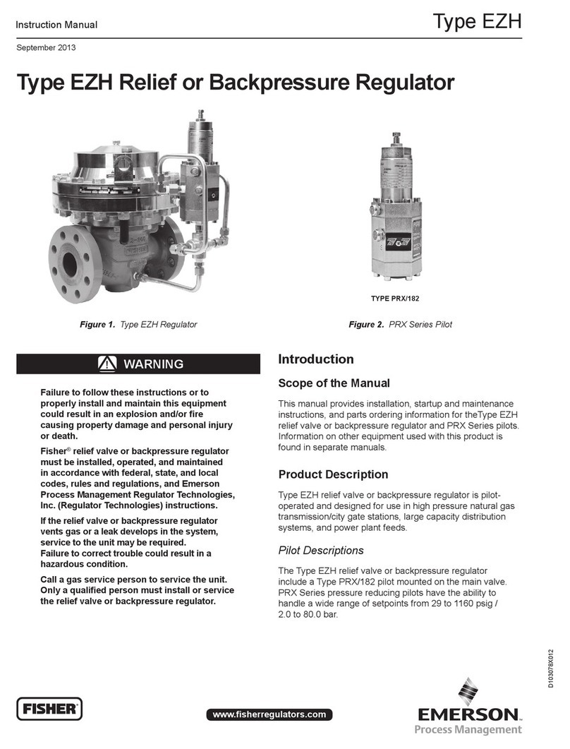
Parts Ordering
When corresponding with the local Sales Ofce or
about this regulator, include the type number and all
other pertinent information stamped on the closing
cap or nameplate. Specify the eleven-character part
number when ordering new parts from the following
parts list.
6
Y696VR Series
