GB
5
Do not leave the room closed
for long. Periodically open
the windows to ensure proper
ventilation.
This instruction booklet is an
integral part of the appliance
and, therefore, it must be kept
with care and must ALWAYS
accompany the appliance, even
when the latter is transferred
to another owner or user or
transferred to another system. If
it gets damaged or lost, please
request another copy from
the local Technical Assistance
Service.
Repairs or maintenance must
be performed by the Technical
Assistance Department or by
skilled personnel in accordance
with this manual.
Do not modify or tamper with the
applianceashazardoussituations
may be generated and the
appliance manufacturer shall not
be held liable for any damage
caused.
BASIC
SAFETY RULES
The use of products that use
electricity and water requires the
observation ofsome fundamental
safety rules such as:
Use of the appliance by children
and unassisted disabled persons
is prohibited.
It is forbidden to touch the
appliance if you are barefoot or
when parts of the body are wet
or damp.
Any cleaning operation is
prohibited before disconnecting
the appliance from the mains
power supply by placing the main
system switch on "off".
It is forbidden to modify the safety
or adjustment devices without
the authorization and the
manufacturer's directions
unit.
It is forbidden to pull, disconnect
or twist the electrical cables
coming out of the appliance,
even if it is disconnected from
the mains.
It is forbidden to introduce objects
and substances through the air
intake and delivery grilles..
OVERVIEW
GENERAL INFORMATION
Thank you for choosing an EMMETI
Thin fan coil unit to air condition
your rooms. Please read this user
and installation manual carefully
before installing and operating
the appliance. By following the
suggestions below you will be able
to maintain the performance of the
appliance over time. In compliance
withEuropeanregulation99/44/EEC,
the manufacturer guarantees the
machine for 24 months from
the date of purchase (without
prejudice to any commercial
warranty extensions), for any
manufacturing defects. Any
other problem related to incorrect
installation, extraordinary
weathering, non-conforming
sizing and unauthorised
tampering is excluded.
Conformity
EMMETI Thin fan coil units conform
to European Directives:
• Low Voltage Directive
(LVD) 2014/35/EU;
• Electromagnetic compatibility Direc-
tive (EMC) 2014/30/EU;
• RoHS Directive 2011/65/EC
• WEEE Directive 2012/19/EU
Symbols
The pictograms shown in the
following chapter allow you to
provide information, quickly and
unequivocally, which is necessary
for the machine to be used correctly
and safely.
Index
- The paragraphs preceded by
this symbol contain crucial
information and prescriptions,
regarding safety in particular.
Failure to comply may result in:
- risks for operator safety
- loss of the warranty
- disclaimed liability by the
manufacturer.
General hazard
- if the operation described is not
performed in compliance with
safety regulations, there may
be a risk of suffering physical
damage.
Electrical hazard
- if the operation described is
not performed in compliance
with the safety regulations,
there lies the risk of suffering
physical damage due to
contact with live elements.
GENERAL
WARNINGS
After unpacking, check that the
contents are intact and that all
parts are included. If not, contact
EMMETI who sold the appliance
to you.
The packaging contains:
- fan coil unit
- thermal insulation for valve
and retainer
- 2 brackets
- user and installation manual
- paper template.
The appliance must be installed
by an authorised EMMETI. Once
the work is done, it must issue
a declaration of conformity
to the client in compliance
with current regulations and
with the indications in the
instruction manual supplied y the
manufacturer with the appliance.
These appliances have been
designed for conditioning and/
or heating rooms and they
must be destined solely for this
purpose, in accordance with their
performance characteristics.
The manufacturer refuses any
contractual or extra-contractual
liability for damage caused to
people, animals or property
resulting from incorrect
installation, adjustment,
maintenance or improper use.
In the event of water leaks, turn
off the main switch and close the
water taps.
Immediately call the Technical
Assistance Service EMMETI or
other qualied personnel and do
not intervene personally on the
appliance.
The recessed ETI series THIN
have no grids or a cover cabinet.
Provide protective elements
and air supply/return grids to
prevent accidental contact with
the appliance.
The following steps must be
carried out if the appliance is
not to be used for a long period:
- Set the master switch of the
system to “off”
- Close the water valves
- If there is a risk of frost,
make surethat antifreeze liquid
has been added to the system,
otherwise empty the system.
A temperature that is too high or
too low is harmful to health and is
an unnecessary waste of energy.
Avoid prolonged direct contact
with the air ow.
It is forbidden to open the access
doors to the internal parts
of the appliance, without having
rst placed the main system
switch on “off”.
It is forbidden to disperse and
leave the packaging material
within the reach of children as
it can be
potential source of danger.
It is forbidden to stand on the
appliance and / or lean against it
any type of object.
The appliance can reach
temperatures on external
components above 70 ° C
BE VERY CAREFUL
TO ANY CONTACT MADE,
RISK OF BURNS.
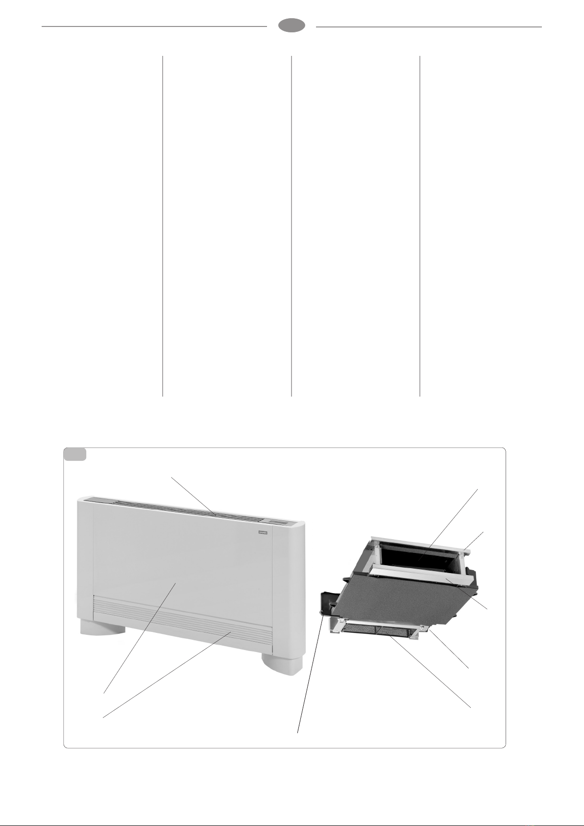
PRODUCT RANGE
Fan coil units of the Thin range
care are divided into 2 basic
types: ETM and ETI – each of
which has different performance
and dimensions
ETM
fan coil unit (suitable for
horizontal or vertical installa-
tions). The horizontal conden-
sate drain pan kit accessories
are available to install the
ETM versions
ETM BRC20 BRC40 BRC60
BRC80
ETI
recessed fan coil unit with no
panelling (suitable for horizontal
or vertical installations).
ATTENTION
It is understood that this equip-
ment is not intended for use
by persons (including children)
with reduced physical, sensory
or mental abilities and must
not be used by people with no
knowledge and experience of the
product. They must be instructed
and monitored while using the
equipment by a person who is
responsible for their safety.