Endress+Hauser Prothermo NMT 539 User manual

Products Solutions Services
BA01025G/08/EN/22.18
71397855
Operating Instruction
Average Temperature
Prothermo NMT539

Prothermo NMT539
2Endress+Hauser
Table of contents
1 Safety Instructions . . . . . . . . . . . . . . . . . . . . . . . . . . . . 3
1.1 Designated use . . . . . . . . . . . . . . . . . . . . . . . . . . . . . . . . . 3
1.2 Installation, commissioning, and operation . . . . . . . . . 3
1.3 Product requirements . . . . . . . . . . . . . . . . . . . . . . . . . . . 3
1.4 Operational safety . . . . . . . . . . . . . . . . . . . . . . . . . . . . . . 4
1.5 Notes on safety conventions and symbols . . . . . . . . . . 4
1.6 Symbols for certain types of information . . . . . . . . . . . 4
2 Identification . . . . . . . . . . . . . . . . . . . . . . . . . . . . . . . . . 5
2.1 Device designation . . . . . . . . . . . . . . . . . . . . . . . . . . . . . . 5
2.2 Order information . . . . . . . . . . . . . . . . . . . . . . . . . . . . . . 9
2.3 Scope of delivery . . . . . . . . . . . . . . . . . . . . . . . . . . . . . . . . 9
2.4 Certificates and approvals . . . . . . . . . . . . . . . . . . . . . . . . 9
2.5 Registered trademarks . . . . . . . . . . . . . . . . . . . . . . . . . . . 9
3 Installation . . . . . . . . . . . . . . . . . . . . . . . . . . . . . . . . . . 10
3.1 Incoming acceptance, transportation, and storage . . 10
3.2 Installation conditions . . . . . . . . . . . . . . . . . . . . . . . . . . 11
3.3 Installation guide for NMT539 . . . . . . . . . . . . . . . . . . . 18
3.4 Protective cover . . . . . . . . . . . . . . . . . . . . . . . . . . . . . . . . 28
4 Wiring . . . . . . . . . . . . . . . . . . . . . . . . . . . . . . . . . . . . . . 29
4.1 Mechanical connection for converter . . . . . . . . . . . . . 29
4.2 Wiring connection for converter . . . . . . . . . . . . . . . . . . 31
4.3 Electrical connection (TIIS, Ex d [ia]) . . . . . . . . . . . . . . 32
4.4 Terminal connection . . . . . . . . . . . . . . . . . . . . . . . . . . . 34
5 Maintenance . . . . . . . . . . . . . . . . . . . . . . . . . . . . . . . . 40
5.1 Periodic inspection . . . . . . . . . . . . . . . . . . . . . . . . . . . . 40
5.2 Repairs . . . . . . . . . . . . . . . . . . . . . . . . . . . . . . . . . . . . . . 40
5.3 Repairs to Ex-approved devices . . . . . . . . . . . . . . . . . . 40
5.4 Replacement . . . . . . . . . . . . . . . . . . . . . . . . . . . . . . . . . . 40
6 Accessories. . . . . . . . . . . . . . . . . . . . . . . . . . . . . . . . . . 41
6.1 Anchor weight for high profile . . . . . . . . . . . . . . . . . . 41
6.2 Anchor weight for low profile . . . . . . . . . . . . . . . . . . . .42
6.3 Wire hook . . . . . . . . . . . . . . . . . . . . . . . . . . . . . . . . . . . . 42
6.4 Top anchor. . . . . . . . . . . . . . . . . . . . . . . . . . . . . . . . . . . . 43
7 Troubleshooting . . . . . . . . . . . . . . . . . . . . . . . . . . . . . 44
7.1 System error messages . . . . . . . . . . . . . . . . . . . . . . . . . 44
7.2 Return. . . . . . . . . . . . . . . . . . . . . . . . . . . . . . . . . . . . . . . . 47
7.3 Disposal . . . . . . . . . . . . . . . . . . . . . . . . . . . . . . . . . . . . . . 47
7.4 Software history . . . . . . . . . . . . . . . . . . . . . . . . . . . . . . . 47
8 Technical data . . . . . . . . . . . . . . . . . . . . . . . . . . . . . . . 48
9 Appendix . . . . . . . . . . . . . . . . . . . . . . . . . . . . . . . . . . . 50
9.1 Description of functions . . . . . . . . . . . . . . . . . . . . . . . . 50
9.2 Function and system design . . . . . . . . . . . . . . . . . . . . . 50
Table of contents

Prothermo NMT539
Endress+Hauser 3
1SafetyInstructions
1.1 Designated use
Average Temperature Prothermo NMT539 is a multi-spot Pt100 average thermometer combined with
a local HART signal converter to meet the demand of temperature measurement for inventory control
applications. NMT539 consists of Max. 6 temperature elements which have different length with fixed
(2 m or 3 m) interval. It is best suited connected to Proservo NMS5, NMS7, NM8x, Micropilot NMR8x,
Tank side monitor NRF81, NRF560 and Digital transmitter TGM5 and TMD1. Mounted on the tank
top, NMT539 provides temperature information on the two wire, intrinsically safe (i.s.) powered local
HART loop.
1.2 Installation, commissioning, and operation
•Mounting, electrical installation, start-up, and maintenance of the instrument may only be per-
formed by trained personnel authorized by the operator of the facility.
•Personnel must read and understand these installation instructions before performing the proce-
dures.
•The instrument may only be operated by personnel who are authorized and trained by the operator
of the facility. All instructions in this manual must be observed.
•The installer must make sure that the measuring system is correctly wired according to the wiring
diagrams. The measuring system must be grounded.
•Observe all law and regulations applicable and valid for your country and pertaining to the opening
and repairing of electrical devices.
1.3 Product requirements
Power source
Check the voltage of the power supply before connecting it to the product. It should be the exact voltage
required for proper operation of the product.
Connection to other devices
It is possible to connect to other devices explained in this instruction. Refer to each operation instruc-
tion when connecting to devices.
Ground
Do not remove earth terminal or earth wire when the power is on.
Power cable
Use a power cable specified by our company. The product should be protectively grounded before it is
connected to a measurement object or an external control circuit.
1 Safety instructions

Prothermo NMT539
4Endress+Hauser
1.4 Operational safety
Hazardous area
•Use the explosion proof type for measurement in areas where explosion hazards are present.
•Devices installed in areas having explosion hazards must not be opened when the power is on.
•Strict compliance with installation instructions and - ratings, as directed in this supplementary doc-
umentation, is mandatory.
•Device maintenance and repair is restricted to meet explosion proof regulations.
•Tighten the cable gland firmly.
•Devices employed in areas having explosion hazards should be installed and wired in keeping with
explosion proof regulations.
•Ensure that all personnel are properly qualified.
•Observe the certification requirements as well as national and local regulations.
Changes or modifications other than those expressly approved by Endress+Hauser
are strictly prohibited. Unauthorized modifications can cause malfunction or dam-
age, resulting in serious injury or death.
1.5 Notes on safety conventions and symbols
To highlight safety-relevant or alternative operating procedures in this manual, the following conven-
tions have been used, each indicated by a corresponding symbol on the left.
1.6 Symbols for certain types of information
Symbol Meaning
A0011189-EN
DANGER!
This symbol alerts you to a dangerous situation. Failure to avoid this situation will result in
serious or fatal injury.
A0011190-EN
WARNING!
This symbol alerts you to a dangerous situation. Failure to avoid this situation can result in
serious or fatal injury.
A0011191-EN
CAUTION!
This symbol alerts you to a dangerous situation. Failure to avoid this situation can result in
minor or medium injury.
A0011192-EN
NOTICE!
This symbol contains information on procedures and other facts which do not result in
personal injury.
Symbol Meaning
A0011182
Allowed
Indicates procedures, processes or actions that are allowed.
A0011183
Recommendation
Indicates procedures, processes or actions that are recommended.
A0011184
Forbidden
Indicates procedures, processes or actions that are forbidden.
A0011193
Tip
Indicates additional information.
WARNING
DANGER
WARNING
CAUTION
NOTICE
1 Safety instructions

Prothermo NMT539
Endress+Hauser 5
2 Identification
2.1 Device designation
2.1.1 Nameplate
The follow technical data are given on the instrument nameplate:
Figure 1: NMT539 module nameplate
1. Order code
2. Serial number
3. Flexible tube length
4. Measuring temperature range
5. Date of manufacture (MM/YY)
Figure 2: TIIS Ex ia approval nameplate 1
A Average temperature and water bottom sensor (TIIS number: TC18319)
B NMT 539 for Hight temperature (TIIS number: TC18320)
Order code
Serial no.
L = mm
Span 䉝㻌㹼ࠉ 䉝Mfg.
NP-2162-5
PROTHERMO
Yamanashi 406-0846
1
2
3
4
㸦㸧
5
4
㸦ࣟ㸧
ᆺᘧ㸸ᆺᘧ㖭ᯈࡢOrder codeཧ↷
㜵⇿ᵓ㐀➼㸸Ex ia IIB T4ࠉ
ᐃ᱁㸸Ui= 30 V, Ii = 120 mA, Pi = 1 W,
ࠉࠉ/L ȝ+&L Q)
࿘ᅖ ᗘ㸸-20㹼+60Υ
⿕ ᐃ≀ ᗘ㸸-20㹼+100Υ
ὀព㸸ᶵჾෆ㒊ࡢ㒊ရཬࡧ㓄⥺ࡢኚ᭦ࠊᨵ㐀➼ࢆ
⾜࡞ࢃ࡞࠸࡛ࡃࡔࡉ࠸ࠋ
ࠉࠉࠉỈᑻࢭࣥࢧ࣮ࡣࠊ㟼㟁Ẽࡀᖏ㟁ࡋ࡞࠸ࡼ࠺
ࠉࠉࠉὀពࡋ࡚ྲྀࡾᢅࡗ࡚ࡃࡔࡉ࠸ࠋ
L
㜵⇿ὀព㡯ㄝ᭩
Ex463-820XJཧ↷
NP-2563-2
<DPDQDVKL
ỺὅἛἾἋἡỸἈὊޛషఇࡸ˟ᅈ
0DGHLQ-DSDQ
3527+(502107
IP65, NEMA 4X
ᆺᘧ㸸ᆺᘧ㖭ᯈࡢOrder codeཧ↷
㜵⇿ᵓ㐀➼㸸Ex ia IIB T2ࠉ
ᐃ᱁㸸Ui = 30 V, Ii = 120 mA, Pi = 1 W,
ࠉࠉ/L ȝ+&L Q)
࿘ᅖ ᗘ㸸-20㹼+60Υ
⿕ ᐃ≀ ᗘ㸸-20㹼+235Υ
ὀព㸸ᶵჾෆ㒊ࡢ㒊ရཬࡧ㓄⥺ࡢኚ᭦ࠊᨵ㐀➼ࢆ
⾜࡞ࢃ࡞࠸࡛ࡃࡔࡉ࠸ࠋ
L
㜵⇿ὀព㡯ㄝ᭩
([;-ཧ↷
NP-2565-2
<DPDQDVKL
ỺὅἛἾἋἡỸἈὊޛషఇࡸ˟ᅈ
0DGHLQ-DSDQ
IP65, NEMA 4X
3527+(502107
A B
2 Identification

Prothermo NMT539
6Endress+Hauser
Figure 3: TIIS Ex ia approval nameplate 2
A Only for transmitter (TIIS number: TC18321)
B NMT539 for low temperature (TIIS number: TC18604)1
Figure 4: TIIS Ex d [ia] approval nameplate (TIIS number: TC18884)
1. Order code
2. Serial number
3. Flexible tube length
4. Measuring temperature range
5. Date of manufacture (MM/YY)
6. Consumption
Figure 5: ATEX Ex ia approval
AConverter
B Average temperature and water bottom sensor
1. Temperature class
2. Maximum ambient temperature
㜵⇿ὀពㄝ㡯᭩
Ex496-826XJཧ↷
ᆺᘧ㸸ᆺᘧ㖭ᯈࡢOrder codeཧ↷
㜵⇿ᵓ㐀➼㸸Ex ia IIB T4
㟁※ᅇ㊰㸸
Ui = 30 V, Ii = 120 mA, Pi = 1W,
ࠉࠉࠉࠉ
/L ȝ+&L Q)
ᢠయᅇ㊰㸸
ࠉࠉ8R 9,R P$3R P:
/R P+&R ȝ)
࿘ᅖ ᗘ㸸-20㹼+60Υ
L
13
<DPDQDVKL
ỺὅἛἾἋἡỸἈὊޛషఇࡸ˟ᅈ
0DGHLQ-DSDQ
ὀព㸸ᶵჾෆ㒊ࡢ㒊ရཬࡧ㓄⥺ࡢኚ᭦ࠊᨵ㐀➼ࢆ
⾜࡞ࢃ࡞࠸࡛ࡃࡔࡉ࠸ࠋ
,31(0$;
3527+(502107
ᆺᘧ㸸ᆺᘧ㖭ᯈࡢOrder codeཧ↷
㜵⇿ᵓ㐀➼㸸Ex ia IIB T4ࠉ
ᐃ᱁㸸Ui = 30 V, Ii = 120 mA, Pi = 1 W,
ࠉࠉ/L ȝ+&L Q)
࿘ᅖ ᗘ㸸 -20㹼+60Υ
⿕ ᐃ≀ ᗘ㸸㹼+60Υ
ὀព㸸ᶵჾෆ㒊ࡢ㒊ရཬࡧ㓄⥺ࡢኚ᭦ࠊᨵ㐀➼ࢆ
ࠉࠉࠉ⾜࡞ࢃ࡞࠸࡛ࡃࡔࡉ࠸ࠋ
L
㜵⇿ὀព㡯ㄝ᭩
([;-ཧ↷
NP-2599-1
<DPDQDVKL
ỺὅἛἾἋἡỸἈὊޛషఇࡸ˟ᅈ
0DGHLQ-DSDQ
,31(0$;
3527+(502107
A B
Order code
Serial no.
L = mm
Span Υ㹼Υ
Mfg. date
警告 /WARNING㸸
ࠉࠉ࣭ᶵჾෆ㒊ࡢ㒊ရཬࡧ㓄⥺ࡢኚ᭦ࠊᨵ㐀➼ࢆ⾜࡞ࢃ࡞࠸࡛ࡃࡔࡉ࠸ࠋ
Don't modify parts and circuits of this instrument.
ࠉࠉ࣭㏻㟁≧ែ࡛ࡣಖㆤ࢝ࣂ࣮ࢆእࡉ࡞࠸࡛ࡃࡔࡉ࠸ࠋ
Don’t remove the protrction cover when energized.
ࠉࠉ࣭Ỉᑻ㺜㺻㺙㺎ࡣࠊ㟼㟁Ẽࡀᖏ㟁ࡋ࡞࠸ࡼ࠺ὀពࡋ࡚ྲྀࡾᢅࡗ࡚ࡃࡔࡉ࠸ࠋ
Avoid electrostatic charge at the plastic surface.
ࠉࠉ࣭
⪏⇕ ᗘΥ௨ୖࡢࢣ࣮ࣈࣝࢆ⏝ࡋ࡚ࡃࡔࡉ࠸ࠋ
Use heat-resistant cable 70Υor more.
L
㜵⇿ὀព㡯ㄝ᭩(Ex1061-986XJ)ཧ↷
Refer to Ex-manual (Ex1061-986XJ)
NP-2612-1
ỺὅἛἾἋἡỸἈὊޛషఇࡸ˟ᅈ
ᆺᘧ / Type: (Order codeࢆཧ↷)/(Refer to Order code)
㜵⇿ᵓ㐀➼ / Ex class㸸Ex d[ia] IIB T4
㠀ᮏᏳᅇ㊰ / non-I.S. circuit㸸
㟁※ /Power DC 20㹼26.4 V, ࠉࠉࠉ mA
ࠉチᐜ㟁ᅽ / Um AC 250 V 50/60 Hz DC 250 V
ᮏᏳᅇ㊰ / I.S.cercuit㸸
Uo = 28.9 V Io = 98 mA Po = 0.71 W
࿘ᅖ ᗘ / Ambient temperature : -20 㹼+60 Υ
⿕ ᐃ≀ ᗘ / Medium tempemperature : -20 㹼+100 Υ
Yamanashi 406-0846
Made in Japan
Endress+Hauser Yamanashi Co.,Ltd.
PROTHERMO NMT539
IP65, NEMA 4X
1
2
3
4-a 4-b 6
5
A B
Ex ia IIB T Ga/Gb
ATEX II 1/2 G
KEMA 03 ATEX 1448 X
NP-2464-7
Warning:
- Don't modify parts and circuits of this instrument.
- Avoid electrostatic charge at the plastic surface.
Ambient temperature: -40 ~ Υ
IP65, NEMA 4X
PROTHERMO NMT539
Yamanashi 406-0846
Made in Japan
Endress+Hauser Yamanashi Co.,Ltd.
Ui < 30 V Ii < 120 mA Pi < 1 W
Ci = 7.9 nF
/L ȝ+
0044
1
2
Warning:
- Don't modify parts and circuits of this instrument.
Ex ia IIB T2..6 Gb
ATEX II 2 G
KEMA 03 ATEX 1448 X
Supply circuit; Ui < 30 V Ii < 120 mA Pi < 1 W
Temperature measurement circuit;
Uo = 8.6 V Io = 71 mA Po = 153 mW
&R ȝ)/R P+
Ci = 7.9 nF
/L ȝ+
NP-2463-8
Ambient temperature: -40 ~ +85Υ
PROTHERMO NMT539
Yamanashi 406-0846
Made in Japan
Endress+Hauser Yamanashi Co.,Ltd.
0044
IP65, NEMA 4X
2 Identification

Prothermo NMT539
Endress+Hauser 7
Figure 6: FM C/US approval nameplate
AConverter
B Average temperature and water bottom sensor
1. Temperature class
2. Maximum ambient temperature
3. XA revision number
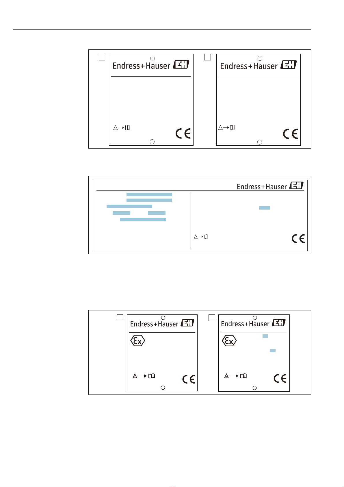
Figure 7: cFMus approval nameplate (Converter + Temperature + WB)
A cFMus approval nameplate (English)
B cFMus approval nameplate (France)
1. Range of measured temperature
2. Maximum ambient temperature
Figure 8: cFMus approval nameplate (Converter only)
Ambient temperature: -40 ~ Υ
NP-2527-2
Warning:
- Don't modify parts and circuits of this instrument.
Supply circuit; Ui < 30 V Ii < 120 mA Pi < 1 W
Temperature measurement circuit;
Uo = 8.6 V Io = 71 mA Po = 153 mW
&R ȝ)/R P+
&L Q)
/L ȝ+
IS Cl. I, Div. 1, Gp. C,D
Cl. I, Zone0, AEx ia IIB T4
NI Cl. I, Div. 2, Gp. C,D
Install per control drawing
No. Ex461-851
Ambient temperature: -40 ~ +85Υ
NEMA 4X, IP65
3527+(502107
Yamanashi 406-0846
Made in Japan
(QGUHVV+DXVHU<DPDQDVKL&R/WG
Ui< 30 V ࠉIi < 120 mA ࠉPi < 1 W
&L Q)/L ȝ+
Warning:
- Don't modify parts and circuits of this instrument.
- Avoid electrostatic charge at the plastic surface.
NP-2528-2
IS Cl. I, Div. 1, Gp. C,D
Cl. I, Zone0, AEx ia IIB T
NI Cl. I, Div. 2, Gp. C,D
Install per control drawing
No. Ex461-850
NEMA 4X, IP65
3527+(502107
Yamanashi 406-0846
Made in Japan
(QGUHVV+DXVHU<DPDQDVKL&R/WG
A B
1
2
3
3
NP-2528-3
Type 4X
PROTHERMO NMT539
0044
Supply circuit; Ui = 30 V Ii = 120 mA Pi = 1 W
Ci = 6.6 nF
/L ȝ+
Warning:
- Don't modify parts and circuits of this instrument.
- Avoid electrostatic charge at the plastic surface.
Endress+Hauser Yamanashi Co.,Ltd.
Yamanashi 406-0846
Made in Japan
Install per control drawing
C: Ex462-711-3
US: Ex461-850-2
Ambient temperature: -40 ~ Υ
C : IS Cl. I, Div. 1, Gp. C,D T*
IS Cl. I, Zone 0, Ex ia IIB T* Ga
US: IS Cl. I, Div. 1, Gp. C,D T*
Cl. I, Zone 0, AEx ia IIB T* Ga
NI Cl. I, Div. 2, Gp. C,D T*
T* = T
C : FM17CA0088
US: FM17US0168
21
NP-2730
Type 4X
PROTHERMO NMT539
0044
Circuit d'alimentation; Ui = 30 V Ii = 120 mA Pi = 1 W
Ci = 6.6 nF /L ȝ+
Attention:
- Ne modifiez pas les pièces et les circuits de cet instrument.
- Évitez la charge électrostatique sur la surface plastique.
Endress+Hauser Yamanashi Co.,Ltd.
Yamanashi 406-0846
Fabriqué au Japon
Installation par dessin de contrôle
C: Ex462-711-3
US: Ex461-850-2
Température ambiante : -40 ~ Υ
C : IS Cl. I, Div. 1, Gp. C,D T*
IS Cl. I, Zone 0, Ex ia IIB T* Ga
US: IS Cl. I, Div. 1, Gp. C,D T*
Cl. I, Zone 0, AEx ia IIB T* Ga
NI Cl. I, Div. 2, Gp. C,D T*
T* = T
C : FM17CA0088
US: FM17US0168
1
2
A B
NP-2527-3
Type 4X
PROTHERMO NMT539
0044
Ambient temperature: -40 ~ +85Υ
Supply circuit; Ui = 30 V Ii = 120 mA Pi = 1 W
Ci = 6.6 nF
/L ȝ+
Temperature measurement circuit;
8R 9,R P$3R P:&R ȝ)/R P+
Warning:
- Don't modify parts and circuits of this instrument.
Endress+Hauser Yamanashi Co.,Ltd.
Yamanashi 406-0846
Made in Japan
Install per control drawing
C: Ex462-712-3
US: Ex461-851-2
C : IS Cl. I, Div. 1, Gp. C,D T4
IS Cl. I, Zone1, Ex ia IIB T4 Ga
US: IS Cl. I, Div. 1, Gp. C,D T4
Cl. I, Zone1, AEx ia IIB T4 Ga
NI Cl. I, Div. 2, Gp. C,D T4
C : FM17CA0088
US: FM17US0168
A
B
NP-2731
Type 4X
PROTHERMO NMT539
0044
Température ambiante: -40 ~ +85Υ
Circuit d'alimentation; Ui = 30 V Ii = 120 mA Pi = 1 W
Ci = 6.6 nF /L ȝ+
Circuit de mesure de la température;
8R 9,R P$3R P:&R ȝ)/R P+
Attention:
- Ne modifiez pas les pièces et les circuits de cet instrument.
Endress+Hauser Yamanashi Co.,Ltd.
Yamanashi 406-0846
Fabriqué au Japon
Installation par dessin de contrôle
C: Ex462-712-3
US: Ex461-851-2
C : IS Cl. I, Div. 1, Gp. C,D T4
IS Cl. I, Zone1, Ex ia IIB T4 Ga
US: IS Cl. I, Div. 1, Gp. C,D
Cl. I, Zone1, AEx ia IIB T4 Ga
NI Cl. I, Div. 2, Gp. C,D
C : FM17CA0088
US: FM17US0168
2 Identification

Prothermo NMT539
8Endress+Hauser
Figure 9: PTB W&M approval nameplate
Figure 10: IEC approval nameplate
AConverter
B Average temperature and water bottom sensor
1. Temperature class
2. Maximum ambient temperature
Figure 11: NEPSI approval nameplate
AConverter
B Average temperature and water bottom sensor
1. Temperature class
2. Maximum ambient temperature
Figure 12: EAC approval nameplate
Hersteller / Producer :
Baujahr
Year of constr.
Tank-Nr.
Tank no.
T
prozess/proces
NP-2593-1
14.70
08.01
min.-20 Υmax.+120 Υ
PROTHERMO NMT539
Warning:
- Don't modify parts and circuits of this instrument.
Ex ia IIB T2..6 Gb
IECEx KEM 10.0058X
Supply circuit; Ui < 30 V Ii < 120 mA Pi < 1 W
Temperature measurement circuit;
Uo = 8.6 V Io = 70.8 mA Po = 153 mW
&R ȝ)/R P+
&L Q)/L ȝ+
NP-2623-1
$PELHQWWHPSHUDWXUHaΥ
,31(0$;
3527+(502107
<DPDQDVKL
Made in Japan
(QGUHVV+DXVHU<DPDQDVKL&R/WG
$PELHQWWHPSHUDWXUHaΥ
Ex ia IIB T Ga/Gb
IECEx KEM 10.0058X
Warning:
- Don't modify parts and circuits of this instrument.
- Avoid electrostatic charge at the plastic surface.
13
Ui < 30 V Ii < 120 mA Pi < 1 W
&L Q)
/L ȝ+
,31(0$;
<DPDQDVKL
Made in Japan
(QGUHVV+DXVHU<DPDQDVKL&R/WG
3527+(502107
A B
1
2
Warning:
- Don't modify parts and circuits of this instrument.
Supply circuit; Ui < 30 V Ii < 120 mA Pi < 1 W
Temperature measurement circuit;
Uo = 8.6 V Io = 70.8 mA Po = 153 mW
&R ȝ)/R P+
&L Q)/L ȝ+
NP-2696
$PELHQWWHPSHUDWXUHaΥ
,31(0$;
3527+(502107
<DPDQDVKL
Made in Japan
(QGUHVV+DXVHU<DPDQDVKL&R/WG
Ex ia IIB T2..6 Gb
*<-
XA01259G-*/08
Warning:
- Don't modify parts and circuits of this instrument.
- Avoid electrostatic charge at the plastic surface.
NP-2697
Ex ia IIB T Ga/Gb
*<-
Ui < 30 V Ii < 120 mA Pi < 1 W
&L Q)
/L ȝ+
$PELHQWWHPSHUDWXUHaΥ
,31(0$;
<DPDQDVKL
Made in Japan
(QGUHVV+DXVHU<DPDQDVKL&R/WG
3527+(502107
XA01259G-*/08
1
2
AB
Ǭǫ58&-3ǝǛ%
ǧǚǧǢǨǰǫǜǷ
Ga/Gb Ex ia IIB T6...T2 X
-40°C<Ta<+60°C T6
-40°C<Ta<+85°C T5, T4, T3, T2
2 Identification

Prothermo NMT539
Endress+Hauser 9
2.2 Order information
Detailed ordering information is available from the following sources:
•In the Product Configurator on the Endress+Hauser website: www.endress.com -> Click "Corporate"
-> Select your country -> Click "Products" -> Select the product using the filters and search field ->
Open product page -> The "Configure" button to the right of the product image opens the Product
configurator.
•From your Endress+Hauser Sales Center: www.addresses.endress.com Product Configurator - the
tool for individual product configuration
•Up-to-the-minute configuration data
•Depending on the device: Direct input of measuring point-specific information such as measuring
range or operating language
•Automatic verification of exclusion criteria
•Automatic creation of the order code and its breakdown in PDF or Excel output format
•Ability to order directly in the Endress+Hauser Online Shop
2.3 Scope of delivery
It is essential to follow the instructions concerning the unpacking, transport and storage of measuring
instruments given in the chapter "Incoming acceptance, transport, storage" on.
The scope of delivery consists of:
•Assembled instrument
•Accessories (Mounting Bracket)
Accompanying documentation:
•Operating Manual (this manual)
•Operating Instructions and Description of Instrument Function
•Safety Instruction (XA)
2.4 Certificates and approvals
CE Mark, Declaration of Conformity
The device is designed to meet state-of-the-art safety requirements, has been tested and left the fac-
tory in a condition in which it is safe to operate. The device complies with the applicable standards and
regulations as listed in the EC declaration of conformity and thus complies with the statutory require-
ments of the EC directives. Endress+Hauser confirms the successful testing of the device by affixing to
it the CE mark.
2.5 Registered trademarks
HART®
Registered trademark of HART Communication Foundation, Austin, USA
FieldCare®
Registered trademark of the company Endress+Hauser Flowstone AG, Heinrich, CH
2 Identification

Prothermo NMT539
10 Endress+Hauser
3Installation
3.1 Incoming acceptance, transportation, and storage
3.1.1 Incoming acceptance
Check the packing and contents for any signs of damage.
Check the shipment, and make sure that nothing is missing and that the items match your order.
3.1.2 Transportation
•Follow the safety instructions and conditions of transportation for instruments in excess of 18kg
(40 lbs.).
•Do not lift the measuring instrument by its housing during unpacking.
3.1.3 Storage
Pack the measuring instrument so that it is protected against impacts during storage and transporta-
tion.
The original packing material provides the optimum protection for this.
The allowed storage temperature is -40 to +85 °C (-40 to +185 °F)
3 Installation

Prothermo NMT539
Endress+Hauser 11
3.2 Installation conditions
3.2.1 Dimensions
Figure 13: Converter only (standard PF (NPS) 3/4 universal coupling connection), Unit of measurement: mm (in)
Figure 14: Converter only (for Varec 1700 with M20 threaded connection), Unit of measurement: mm (in)
1. Secure nut
2. Terminal box for Varec 1700 RT probe
UK Special is designed specifically to connect with the average temperature probe of
Whessoe Varec 1700 series. UK Special is not equipped with the water bottom data
accessibility function.
Mounting procedure of UK special M20 connection to Varec 1700 terminal box
1. Use sealing tape on the threaded gauge to terminal box connection. Connect a bunch of cable
(RTD signal inlet cable) into the female thread connection of the terminal box.
2. Turn the entire NMT539 gauge head clockwise 10 times or more and secure it to the terminal box
with a lock nut.
• Make sure that terminal housing connection for NMT539 and Varec1700 is secured.
This completes the mounting procedure.
319 (12.56)
189 (7.44)
48 (1.89)
168 (6.61) 32 (1.26)
1
2
CAUTION
3 Installation

Prothermo NMT539
12 Endress+Hauser
Converter + average temperature probe
Figure 15: Dimensions for converter + average + temperature prob, Unit of measurement: mm (in)
a Adjustable installation height
b Height of the flange (depending on spec.)
c Length of the flexible tube (depending on tank height) (Margin of error for temp. probe length: ±50 mm)
1. SUS316
2. SUS316L
The position of the welded flange can not be adjusted.
Ø104 (4.1)
Ø32 (1.26)
Ø36 (1.42)
194 (7.64)
180 (7.09)
15 (0.6)
180 (7.09)
1
1
1
1
2
a
b
a
c
3 Installation

Prothermo NMT539
Endress+Hauser 13
Converter + temperature + water bottom probe
Figure 16: Dimension of Converter + average temperature probe + WB probe, Unit of measurement: mm (in)
a Adjustable installation height
b Height of the flange (depending on spec.)
c Length of the flexible tube (depending on tank height) (Margin of error for temp. probe length: ±50 mm)
d Capacitance water bottom probe
e Hook for anchor weight (in case that the option is selected)
1. PFA protection tube (thickness: 1 mm)
2. Center rod (SUS304)
3. Pt100 element
4. Base plate/datum plate and side rod (316)
5. Element (Pt100 element can be installed up to 2 points.)
The position of the welded flange can not be adjusted.
Ø104 (4.1)
Ø32 (1.26)
194 (7.64)
180 (7.09)
15 (0.6)
180 (7.09)
10 (0.39)
a
b
a
c
c
5
5
12
3
3
4
4
Ø45 (1.77)
Ø45 (1.77)
e
d
1010/2010 (39.76/79.13)
3 Installation

Prothermo NMT539
14 Endress+Hauser
NMT539 No.1 element position
Figure 17:#1 Element Position,
Unit of measurement: mm (in)
A Transmitter + Temperature probe
B Transmitter + Temperature probe + Water probe
a Distance from the bottom of the flange
b Position of No.1 element
3.2.2 Unpacking procedure
When unpacking NMT539 by only one worker, it may bend or twist the flexible tube. This work must
be handled by three or more workers.
Figure 18: Unpacking procedure for NMT539
244
(9.6)
200
(7.87)
222
(8.74)
500 (19.69)
400 (15.75)
400 (15.75)
a
NMT539 ++++++++A+
a
NMT539 ++++++++A+
a
NMT539 ++++++++A+
100
(3.94)
116
(4.57)
NMT539 -+1,4++++++AA
NMT539 -+1,4++++++AC
NMT539 -+1,4++++++AD/F
NMT539 -+1,4++++++AB
NMT539 -+3,5++++++AA
NMT539 -+3,5++++++AG
NMT539 -+3,5++++++AC
NMT539 -+3,5++++++AD/F
NMT539 -+3,5++++++AB
AB
b
300
(11.81)
3 Installation

Prothermo NMT539
Endress+Hauser 15
3.2.3 Handling of flexible tube
Do not hold the flexible tube at a single point and lift the sensor. This may cause damage to the tube.
Figure 19: Handling of flexible tube
When winding the flexible tube, keep the diameter of the tube at a minimum of 1000 mm (39.37 in)
or more. When bending the flexible tube to attach to a tank, the radius of curved area must be 500mm
(19.69 in) or more.
Figure 20: Handling of flexible tube 2, Unit of measurement: mm (in)
a 1000 mm (39.37 in) or more
R 500 mm (19.69 in) or more
1. Temperature probe
2. Element protection pipe
If the radius of the curved area must be shown above becomes smaller than 500 mm
(19.69 in), the flexible tube or the measuring element may be seriously damaged or
broken.
a
1
R
2
CAUTION
3 Installation

Prothermo NMT539
16 Endress+Hauser
3.2.4 Mounting of NMT539
•The flexible tube length of NMT539 is defined for the customer’s specifications. Before mounting,
check as follows:
1. Tag Number (if any) on the body of NMT539
2. Length of Flexible Tube
3. Number of Measuring Points
4. Intervals between Measuring Points
•Mount NMT539 at a minimum of 500 mm(19.67 in) away from the tank shell. This will ensure that
the measurement is not influenced by changes in ambient temperature.
•The procedure for mounting of NMT539 on a tank varies depending on the type of tank. Procedures
for a fixed roof tank and a floating roof tank are shown in this section as examples. However, pro-
cedures for mounting of the flexible tube head are the same (mounted on the top of the tank) in any
types of tanks.
•The recommended standard diameter of nozzle is 50 mm (2 in).
Figure 21: Mounting NMT539
1. Hexagonal bolt
2. End of the temperature probe
3. Gasket
4. Washer
5. Bolt
6. Nozzle
7. End of the flange
1
2
3
4
5
6
7
3 Installation

Prothermo NMT539
Endress+Hauser 17
Wrapping sealing tape procedure
Wrap the sealing tape around the screwed part shown below at a width of 30 mm (1.18 in)
or more to maintain high level of air sealing between flanges.
1. When the installation height of the probe is set, lift the probe and mark the position of the bottom
of the flange.
2. Turn the flange and moves it up toward the converter unit approximately 30 mm (1.18 in).
3. Wrap sealing tape (e.g. material: PTFE or other appropriate materials) around the adjusting pipe
below the bottom of the flange.
4. Turn the flange back to the marked installation (original) height.
5. Wrap sealing tape around the adjusting pipe above the flange.
6. Turn the lock nut downwards to the flange until it is properly secured.
This completes the wrapping sealing tape procedure.
Figure 22: Wrapping Sealing Tape, Unit of measurement: mm (in)
1. Nut
2. Flange
3. Mark
4. Seal tape
Ensure to keep the tension at of 16kg or less during setting and after setting. Exceed-
ing the limit may cause breakage in the flexible tube.
Figure 23: Mounting accessory
FF
≤16 kg (on setting/after setting)
1. Lowermost element position
2. Hook
NOTICE
/
(1.18)
1
2
4
1. 2. 3. 4. 5. 6.
WARNING
FF
1
1
1
2
2
3 Installation

Prothermo NMT539
18 Endress+Hauser
Safety precaution for use of NMT539 at temperature of -170°C
When NMT539 is installed in cryogenic tanks, pressure in the flexible tube and electrical housing may
decrease due to the rapid cooling of the tank processes. During commissioning of the temperature
probe, loosen the terminal compartment cover to stabilize the pressure. When removing NMT539
from a cryogenic tank, the temperature and pressure in the flexible tube may rapidly increase due to
an extreme temperature difference between the inside and outside of the tank. In this case, the flexible
tube may move in an uncontrolled manner, and could lead to mechanical damage or personal injury.
To prevent this, turn off the power and loosen the terminal compartment cover to stabilize the pres-
sure.
Figure 24: -170°C caution plate
3.3 Installation guide for NMT539
When installing water bottom, check "Zero" reference position of water bottom compared with manual
dipping reference.
3.3.1 Mounting NMT539 on fixed roof tank
There are three methods for mounting NMT539 on a fixed roof tank
1. Top anchor method
2. Stilling well method
3. Anchor weight method
If a heating coil is attached to the bottom of the tank, the clearance between the bottom
hook of the flexible tube and the bottom of the tank may vary depending on the type of
heating coil.
ὀព㸟
ᮏ〇ရࢆᴟప ࡢࢱࣥࢡタ⨨ࠊࡲࡓࡣ
ࢱࣥࢡࡽྲྀࡾฟࡍ㝿ࠊ⣲Ꮚಖㆤ⟶ෆࡢ
ẼᅽࡀᏳᐃࡍࡿࡲ࡛ࠊ➃Ꮚ⟽ࢆእࡋࡓ
≧ែࡋ࡚ࡃࡔࡉ࠸ࠋ
NP-2605-1
CAUTION!
When installing this device on, or removing
this device from, a cryogenic tank, open the
terminal compartment cover to normalize
the internal pressure.
ỺὅἛἾἋἡỸἈὊޛషఇࡸ˟ᅈ
Yamanashi 406-0846
Made in Japan
Endress+Hauser Yamanashi Co.,Ltd.
NOTICE
3 Installation

Prothermo NMT539
Endress+Hauser 19
Top anchor method
The flexible tube and water bottom sensor are fixed with a wire hook and a top anchor.
Figure 25: Top anchor method, Unit of measurement: mm (in)
a Height from the bottom of the tank to the lowermost element
b Interval from the bottom of the tank
c Tank height
1. Electrical compartment
2. Flange
3. Uppermost temperature element
4. Temperature probe
5. Water bottom probe
6. Element position No.1 (lowermost element)
7. Reference position
8. Top anchor
9. Socket
10. Tensioning wire
11. Wire hook
Top anchor attachment procedure
1. Insert a flexible tube and/or WB (Water Bottom) probe into a gasket and lower the flexible tube
from the nozzle at the top of the tank.
The flexible tube and/or WB probe must be lowered carefully without overbending and
scratching the inner edge of the nozzle hole.
2. Rotate NMT539 for cabling in the most convenient way.
3. Straighten the tensioning wire, temporarily fix the end of the wire to the top anchor and lower
the wire.
4. Put the tensioning wire into the wire hook at the bottom of the tank.
5. Secure the tensioning wire twice through the hole at the bottom hook
6. Wind the provided wire around the tensioning wire to secure the tensioning wire.
1
2
3
4
5
6
6
7
8
9
10
11
b
400
(15.75)
c
a
500 (19.69)
36 (1.42) 45 (1.77)
NOTICE
3 Installation

Prothermo NMT539
20 Endress+Hauser
Figure 26: Top anchor attachment-1
1. Tensioning wire
2. Temperature probe
3. Hook for wire
4. Wire hook
5. Water bottom probe
6. Provided wire
1. Using bolts, fix the mounting flange of Prothermo to the nozzle at the top of the tank.
Keep the compression of the spring of 35 to 37mm (1.38 to 1.47 in). Compression exceeding the
spring of 35 to 37 mm (1.38 to 1.47 in) may damage the sensor.
2. Wind the end of the wire once around the shaft of the top anchor and tighten it with nuts (2 pcs.).
3. Cut the excess wire.
4. Screw the nut to compress down the spring of the top anchor from 35 to 37mm (1.38 to 1.47 in).
5. Cover the top anchor.
This completes the mounting top anchor procedure.
Figure 27: Top anchor attachment-2, Unit of measurement: mm (in)
1
2
3
4
5
6
35 - 37
(1.38 - 1.46)
3 Installation
Other manuals for Prothermo NMT 539
5
Table of contents
Other Endress+Hauser Thermometer manuals

Endress+Hauser
Endress+Hauser Omnigrad T TR25 Manual

Endress+Hauser
Endress+Hauser iTHERM CompactLine TM311 User manual

Endress+Hauser
Endress+Hauser iTHERM TrustSens TM371 User manual

Endress+Hauser
Endress+Hauser iTHERM TrustSens TM371 Technical specifications

Endress+Hauser
Endress+Hauser T 62 Series Installation instructions

Endress+Hauser
Endress+Hauser iTHERM TrustSens TM372 User manual

Endress+Hauser
Endress+Hauser Omnigrad M TR13 Manual

Endress+Hauser
Endress+Hauser Omnigrad TR1 Series Installation instructions

Endress+Hauser
Endress+Hauser tmr31 User manual

Endress+Hauser
Endress+Hauser iTHERM TM411 Manual