Compact Instructions
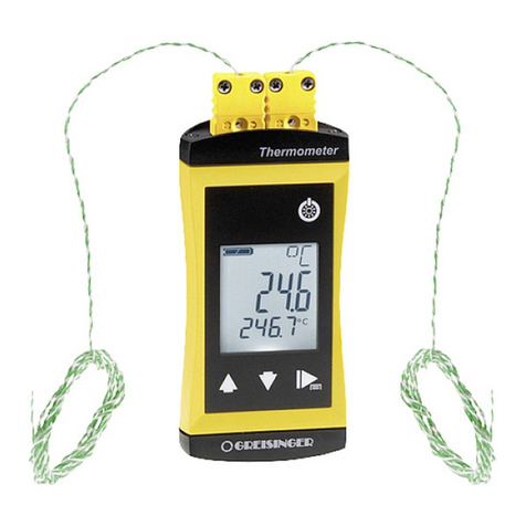
Explosion proof RTD assembly
in Thermowell
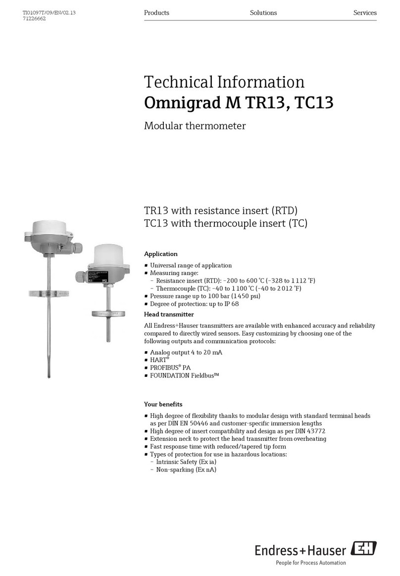
T13
Measuring System
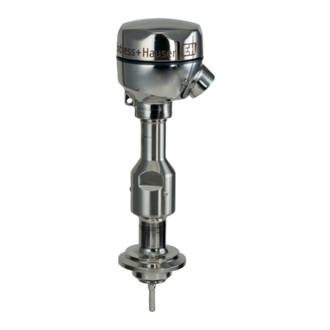
Explosion proof RTD assembly in
Thermowell with spring loaded insert and
enclosure for process industry.
ranges:
(low range RTD -58 °F to 392 °F;
high range RTD -328 °F to 1112 °F).
Performance Characteristics
Maximum measured error (Pt100 / IEC 60751)
Class max. Tolerances (°C)
A ± (0.15 + 0.002 · |t|*), temperature range: -100 °C to 450 °C
B ± (0.3 + 0.005 · |t|*), temperature range: -200 °C to 600 °C
* |t| = absolute value °C. For measurement errors in °F, calculate using equation above in °C, then multiply the outcome by 1.8.
Dielectrical strength The units are factory tested with 850 VDC for one second
between live parts (leads/terminals) and exposed
non-current-carrying metal parts (e.g. insert sheath)
Supplementary documentation
All important Temperature Operating Instructions, particularly with regard to head
number: SONDTT-AG.
Important Notice
Electrical shock could cause death or serious injury. If the sensor is installed in a
high voltage environment and a fault or installation error occurs, high voltage may
be present on the connection terminals or the probe itself.
Safe and secure operation of the temperature sensor can only be guaranteed if the
operating instructions of the used transmitters and all included safety notes are
read, understood and followed. For Endress+Hauser temperature transmitters see
Correct use
The manufacturer cannot be held responsible for damage caused by misuse of the
unit. The installation conditions and connection values indicated in the operating
instructions and control drawings must be followed!
Installation Guidelines and Safety instructions
1. Install the unit according to the relevant NEC Code and local regulations.
2. Avoid any spark due to impact, friction and installation. Anti-sparking
wrenches should be utilized.
3. Approved apparatus must be installed in accordance with manufacturer’s
instructions, see corresponding Control Drawing:
Approval Drawing code
XP DIP Class I, II, III Div. 1+2 CSA ZD053R/09/en
XP NI DIP Class I, II, III Div. 1+2 CSA ZD055R/09/en
XP DIP Class I, II, III Div. 1+2 FM ZD057R/09/en
XP NI DIP Class I, II, III Div. 1+2 FM ZD062R/09/en
The accessories for pipe connections and the appropriate gaskets and sealing rings
are not supplied with the sensors. These are the customer’s responsibility.
Depending on temperature and pressure operating conditions, the gaskets, the
sealing and the applicable torques must be selected by the user.
For further information regarding connections, please refer to the corresponding
Standards.
Installation and operation
The unit is constructed using the most up to date production equipment and
complies with the safety requirements of the local guidelines. However, if it is
installed incorrectly or misused, certain application dangers can occur. Installation,
wiring and maintenance of the unit must only be completed by trained, skilled
personnel who are authorized to do so by the plant operator. The plant operator
must make sure that the measurement system has been correctly wired to the
connection schematics. Procedures indicated in these instructions must be followed.
Returns
Please follow the Return Authorization Policy which is attached with this manual.
Safety pictograms and symbols
on operation or trigger an unforeseen device reaction if they are not carried out
properly.
Cautions draw attention to activities or procedures that can lead to persons being
seriously injured, to safety risks or to the destruction of the device if they are not
carried out properly.
Though the information provided herein is believed to be accurate, be advised that the information contained
patent. Please note that Endress+Hauser reserves the right to change and/or improve the product design and
KA00236R/24/EN/13.12
71208018
www.addresses.endress.com
