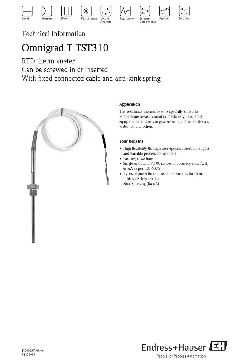
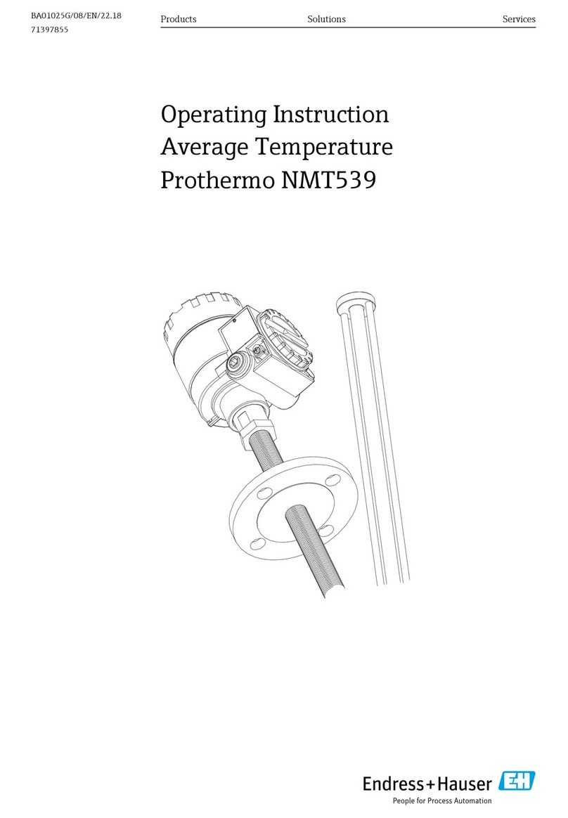
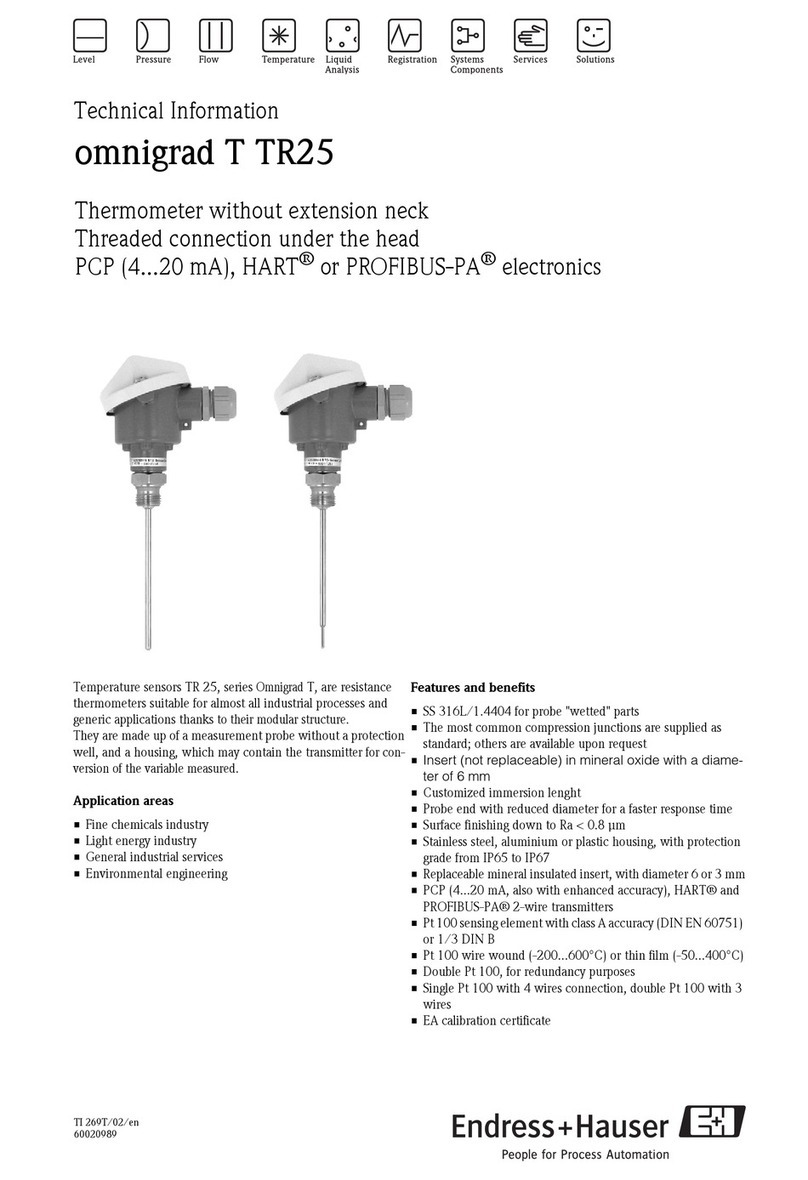
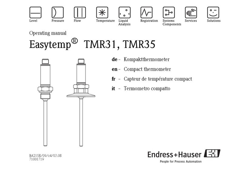
Endress+Hauser iTHERM CompactLine TM311 User manual

Products Solutions Services
Operating Instructions
iTHERM CompactLine TM311
Compact thermometer with IO-Link
BA01952T/09/EN/02.20
71488035
2020-06-29

iTHERM CompactLine TM311
2 Endress+Hauser
Order code:
Ext. ord. cd.:
Ser. no.:
www.endress.com/deviceviewer Endress+Hauser
Operations App
XXXXXXXXXXXX
XXXXX-XXXXXX
XXX.XXXX.XX
Serial number
1.
3.
2.
A0023555

iTHERM CompactLine TM311 Table of contents
Endress+Hauser 3
Table of contents
1 About this document ................ 4
1.1 Document function ..................... 4
1.2 Symbols .............................. 4
1.3 Documentation ........................ 5
1.4 Registered trademarks ................... 6
2 Basic safety instructions ............ 7
2.1 Requirements for the personnel ............ 7
2.2 Designated use ........................ 7
2.3 Operational safety ...................... 7
2.4 Product safety ......................... 7
2.5 IT security ............................ 8
3 Product description ................. 9
4 Incoming acceptance and product
identification ..................... 10
4.1 Incoming acceptance ................... 10
4.2 Product identification ................... 10
4.3 Name and address of manufacturer ........ 11
4.4 Storage and transport .................. 11
5 Installation ....................... 13
5.1 Installation conditions .................. 13
5.2 Installing the thermometer .............. 15
5.3 Post-installation check .................. 17
6 Electrical connection .............. 18
6.1 Connection conditions .................. 18
6.2 Connecting the measuring device .......... 18
6.3 Ensuring the degree of protection .......... 19
6.4 Post-connection check .................. 19
7 Operation options ................. 20
7.1 Protocol-specific data ................... 20
8 System integration ................ 21
8.1 Identification ......................... 21
8.2 Process data ......................... 21
8.3 Reading and writing device data ........... 22
9 Commissioning .................... 25
9.1 Post-installation check .................. 25
9.2 Configuring the measuring device .......... 25
10 Diagnostics and troubleshooting ... 26
10.1 General troubleshooting ................. 26
10.2 Diagnostic information via communication
interface ............................ 26
10.3 Overview of the diagnostic information ..... 27
10.4 Diagnostic list ........................ 28
10.5 Event logbook ........................ 28
11 Maintenance ...................... 29
11.1 Cleaning ............................ 29
11.2 Endress+Hauser services ................ 29
12 Repair ............................ 30
12.1 Spare parts .......................... 30
12.2 Return .............................. 30
12.3 Disposal ............................ 30
13 Accessories ....................... 30
13.1 Device-specific accessories ............... 31
13.2 Communication-specific accessories ........ 34
13.3 Service-specific accessories ............... 36
13.4 System components .................... 37
14 Technical data .................... 38
14.1 Input ............................... 38
14.2 Output ............................. 38
14.3 Power supply ......................... 39
14.4 Performance characteristics .............. 40
14.5 Environment ......................... 42
14.6 Mechanical construction ................ 43
14.7 Certificates and approvals ............... 57
15 Overview of the IO-Link operating
menu ............................. 60
15.1 Description of device parameters .......... 62
About this document iTHERM CompactLine TM311
4 Endress+Hauser
1 About this document
1.1 Document function
These Operating Instructions contain all the information that is required in various phases
of the life cycle of the device: from product identification, incoming acceptance and
storage, to mounting, connection, operation and commissioning through to
troubleshooting, maintenance and disposal.
1.2 Symbols
1.2.1 Safety symbols
DANGER
This symbol alerts you to a dangerous situation. Failure to avoid this situation will result in
serious or fatal injury.
WARNING
This symbol alerts you to a dangerous situation. Failure to avoid this situation can result in
serious or fatal injury.
CAUTION
This symbol alerts you to a dangerous situation. Failure to avoid this situation can result in
minor or medium injury.
NOTICE
This symbol contains information on procedures and other facts which do not result in
personal injury.
1.2.2 Electrical symbols
Symbol Meaning
Direct current
Alternating current
Direct current and alternating current
Ground connection
A grounded terminal which, as far as the operator is concerned, is grounded via a
grounding system.
Protective Earth (PE)
A terminal which must be connected to ground prior to establishing any other
connections.
The ground terminals are situated inside and outside the device:
• Inner ground terminal: Connects the protectiv earth to the mains supply.
• Outer ground terminal: Connects the device to the plant grounding system.
1.2.3 Symbols for certain types of information
Symbol Meaning
Permitted
Procedures, processes or actions that are permitted.
Preferred
Procedures, processes or actions that are preferred.
Forbidden
Procedures, processes or actions that are forbidden.

iTHERM CompactLine TM311 About this document
Endress+Hauser 5
Symbol Meaning
Tip
Indicates additional information.
Reference to documentation.
A
Reference to page.
Reference to graphic.
Notice or individual step to be observed.
1.
,
2.
,
3.
… Series of steps.
Result of a step.
Help in the event of a problem.
Visual inspection.
1.2.4 Symbols in graphics
Symbol Meaning Symbol Meaning
1, 2, 3,... Item numbers
1.
,
2.
,
3.
… Series of steps
A, B, C, ... Views A-A, B-B, C-C, ... Sections
-
Hazardous area
.
Safe area (non-hazardous area)
1.2.5 Tool symbols
Symbol Meaning
A0011222
Open-ended wrench
1.3 Documentation
For an overview of the scope of the associated Technical Documentation, refer to the
following:
•W@M Device Viewer (www.endress.com/deviceviewer): Enter the serial number
from nameplate
•Endress+Hauser Operations App: Enter the serial number from the nameplate or
scan the 2D matrix code (QR code) on the nameplate
1.3.1 Standard documentation
Document type Purpose and content of the document
Technical Information Planning aid for your device
The document contains all the technical data on the device and provides
an overview of the accessories and other products that can be ordered for
the device.
Brief Operating Instructions Guide that takes you quickly to the 1st measured value
The Brief Operating Instructions contain all the essential information
from incoming acceptance to initial commissioning.

About this document iTHERM CompactLine TM311
6 Endress+Hauser
1.3.2 Supplementary device-dependent documentation
Additional documents are supplied depending on the device version ordered: Always
comply strictly with the instructions in the supplementary documentation. The
supplementary documentation is an integral part of the device documentation.
1.4 Registered trademarks
®
Is a registered trademark. It may only be used in conjunction with products and services by
members of the IO-Link Community or by non-members who hold an appropriate license.
For more detailed information on the use of IO-Link, please refer to the rules of the IO-
Link Community at: www.io.link.com.

iTHERM CompactLine TM311 Basic safety instructions
Endress+Hauser 7
2 Basic safety instructions
2.1 Requirements for the personnel
The personnel for installation, commissioning, diagnostics and maintenance must fulfill
the following requirements:
‣Trained, qualified specialists must have a relevant qualification for this specific function
and task.
‣Are authorized by the plant owner/operator.
‣Are familiar with federal/national regulations.
‣Before starting work, read and understand the instructions in the manual and
supplementary documentation as well as the certificates (depending on the
application).
‣Follow instructions and comply with basic conditions.
The operating personnel must fulfill the following requirements:
‣Are instructed and authorized according to the requirements of the task by the facility's
owner-operator.
‣Follow the instructions in this manual.
2.2 Designated use
• The device is a compact thermometer for industrial temperature measurement.
• The manufacturer is not liable for damage caused by improper or non-designated use.
2.3 Operational safety
Risk of injury.
‣Operate the device in proper technical condition and fail-safe condition only.
‣The operator is responsible for interference-free operation of the device.
Conversions to the device
Unauthorized modifications to the device are not permitted and can lead to unforeseeable
dangers.
‣If, despite this, modifications are required, consult with Endress+Hauser.
Repair
To ensure continued operational safety and reliability,
‣Carry out repairs on the device only if they are expressly permitted.
‣Observe federal/national regulations pertaining to repair of an electrical device.
‣Use original spare parts and accessories from Endress+Hauser only.
2.4 Product safety
This measuring device is designed in accordance with good engineering practice to meet
state-of-the-art safety requirements, has been tested, and left the factory in a condition in
which it is safe to operate.
It meets general safety standards and legal requirements. It also complies with the EC
directives listed in the device-specific EC Declaration of Conformity. Endress+Hauser
confirms this by affixing the CE mark to the device.

Basic safety instructions iTHERM CompactLine TM311
8 Endress+Hauser
2.5 IT security
Our warranty is valid only if the device is installed and used as described in the Operating
Instructions. The device is equipped with security mechanisms to protect it against any
inadvertent changes to the settings.
IT security measures, which provide additional protection for the device and associated
data transfer, must be implemented by the operators themselves in line with their security
standards.

iTHERM CompactLine TM311 Product description
Endress+Hauser 9
3 Product description
Design Options
1
2
3
4
56a
6b
A0039771
1: Electrical
connection,
output signal
2: Transmitter
housing
Your benefits:
• M12, 4-pin connector, reduced cost and effort, incorrect wiring is
prevented
• Optimum protection, IP69 as standard
• Compact, integrated transmitter (IO-Link and 4 to 20 mA)
3: Extension neck Optionally available if process temperature is too high for the electronics
4: Process
connection
→ 51
Over 50 different versions for industrial, hygienic and aseptic applications.
5: Thermowell • Versions with and without thermowell (insert in direct contact with process)
• Thermowell diameter 6 mm and optimized T-pieces and elbow pieces
6: Insert with:
6a: iTHERM
TipSens
6b: Pt100 (TF),
basic
Your benefits:
•iTHERM TipSens - insert with shortest response times:
• Insert: 3 mm (¹⁄₈ in) or 6 mm (¹⁄₄ in)
• Fast, highly accurate measurements, delivering maximum process
safety and control
• Quality and cost optimization
• Minimization of necessary immersion length: better product
protection thanks to improved process flow
•Pt100 (TF), basic
• Excellent cost-performance ratio

Incoming acceptance and product identification iTHERM CompactLine TM311
10 Endress+Hauser
4 Incoming acceptance and product
identification
4.1 Incoming acceptance
Proceed as follows on receipt of the device:
1. Check whether the packaging is intact.
2. If damage is discovered:
Report all damage immediately to the manufacturer.
3. Do not install damaged components, as the manufacturer cannot otherwise
guarantee the material resistance or compliance with the original safety
requirements, and can also not be held responsible for the consequences that may
result.
4. Compare the scope of delivery against the contents of your order.
5. Remove all the packaging material used for transportation.
6.
DELIVERY NOTE
A0040102
Do the data on the nameplate match the ordering information on the delivery note?
7.
TMT162
iTHERM CompactLine
TM311
A0040103
Are the technical documentation and all other necessary documents provided e.g.
certificates?
If one of the conditions is not satisfied, contact your Sales Center.
4.2 Product identification
The device can be identified in the following ways:
• Nameplate specifications
• Enter the serial number from the nameplate in the W@M Device Viewer
www.endress.com/deviceviewer: All data relating to the device and an overview of the
Technical Documentation supplied with the device are displayed.

iTHERM CompactLine TM311 Incoming acceptance and product identification
Endress+Hauser 11
4.2.1 Nameplate
The correct device?
1. Check the data on the nameplate of the device.
2. Compare against the requirements of the measuring point.
1
2
3
4
5
6
7
Made in Germany
D-87484 Nesselwang
A0038995
1 Sample graphic
1 Product root, device designation: TM311
2 Order code, serial number
3 Tag name
4 Technical values: supply voltage, current consumption, ambient temperature
5 Degree of protection
6 Pin assignment
7 Approvals with symbols: CE mark, EAC
4.2.2 Scope of delivery
The scope of delivery comprises:
• Compact thermometer
• Printed copy of the Brief Operating Instructions
• Accessories ordered
4.3 Name and address of manufacturer
Name of manufacturer: Endress+Hauser Wetzer GmbH + Co. KG
Address of manufacturer: Obere Wank 1, D-87484 Nesselwang or www.endress.com
Address of manufacturing plant: See nameplate
4.4 Storage and transport
Pack the device so that it is reliably protected against impact when it is stored and
transported. The original packaging offers the best protection.
4.4.1 Storage temperature
Pack the device so that it is reliably protected against impact when it is stored (and
transported). The original packaging offers the best protection.

Incoming acceptance and product identification iTHERM CompactLine TM311
12 Endress+Hauser
Ts–40 to +85 °C (–40 to +185 °F)

iTHERM CompactLine TM311 Installation
Endress+Hauser 13
5 Installation
5.1 Installation conditions
Information on the conditions that must be present at the installation location in
order to ensure designated use (e.g. ambient temperature, degree of protection,
climate class etc.), and information on the device dimensions → 38
5.1.1 Orientation
No restrictions. However, self-draining in the process must be guaranteed. If there is an
opening to detect leaks at the process connection, this opening must be at the lowest
possible point.
5.1.2 Installation instructions
The immersion length of the compact thermometer can considerably influence the
accuracy. If the immersion length is too short, measurement errors can occur as a result of
heat conduction via the process connection and the vessel wall. If installing in a pipe, the
immersion length should ideally correspond to half of the pipe diameter.
Installation possibilities: pipes, tanks or other plant components.
≥ 3°
≥ 3°
1
2
34
U
Lt
Dt dt
A0040370
2 Installation examples
1, 2 Perpendicular to flow direction, installed at a min. angle of 3 ° to ensure self-draining
3 On elbows
4 Inclined installation in pipes with a small nominal diameter
U Immersion length
The requirements of the EHEDG and the 3-A Sanitary Standard must be adhered to.
Installation instructions EHEDG/cleanability: Lt ≤ (Dt-dt)
Installation instructions 3-A/cleanability: Lt ≤ 2(Dt-dt)
In the case of pipes with a small nominal diameter, it is advisable for the tip of the
thermometer to project well into the process so that it extends past the pipe axis.
Installation at an angle (4) could be another solution. When determining the
immersion length or installation depth all the parameters of the thermometer and of
the medium to be measured must be taken into account (e.g. flow velocity, process
pressure).

Installation iTHERM CompactLine TM311
14 Endress+Hauser
A B CD
56
16
1
8
11
9
12
10
2
3
4
7
15
13
14
A0040345
3 Detailed installation instructions for hygiene-compliant installation
A Milk pipe connection according to DIN 11851, only in connection with EHEDG certified and self-centering
sealing ring
1 Sensor with milk pipe connection
2 Groove slip-on nut
3 Counterpart connection
4 Centering ring
5 R0.4
6 R0.4
7 Sealing ring
BVarivent® process connection for VARINLINE® housing
8 Sensor with Varivent connection
9 Counterpart connection
10 O-ring
C Clamp according to ISO 2852
11 Molded seal
12 Counterpart connection
D Process connection Liquiphant-M G1", horizontal installation
13 Weld-in adapter
14 Vessel wall
15 O-ring
16 Thrust collar
The counterpieces for the process connections and the seals or sealing rings are not
included in the scope of supply for the thermometer. Liquiphant M weld-in adapters
with associated seal kits are available as accessories → 30.
NOTICE
The following actions must be taken if a sealing ring (O-ring) or seal fails:
‣The thermometer must be removed.
‣The thread and the O-ring joint/sealing surface must be cleaned.
‣The sealing ring or seal must be replaced.
‣CIP must be performed after installation.
In the case of weld-in connections, exercise the necessary degree of care when performing
the welding work on the process side:
1. Use suitable welding material.
2. Flush-weld or weld with welding radius ≥ 3.2 mm (0.13 in).
3. Avoid crevices, folds or gaps.
4. Ensure the surface is honed and polished, Ra ≤ 0.76 µm (30 µin).

iTHERM CompactLine TM311 Installation
Endress+Hauser 15
Pay attention to the following when installing the thermometer to ensure that the
cleanability is not affected:
1. The installed sensor is suitable for CIP (cleaning in place). Cleaning is performed
together with the pipe or tank. In the case of internal tank fixtures using process
connection nozzles, it is important to ensure that the cleaning assembly directly
sprays this area so that it is cleaned properly.
2. The Varivent® couplings enable flush-mount installation.
5.1.3 General installation instructions
The device generates diagnostic message S825 if a device temperature of 100 °C is
reached due to unfavorable conditions (high process temperature, high ambient
temperature, electronics close to the process). The device generates diagnostic
message F001 or Failure current if the device temperature is 125 °C or higher.
Ambient temperature range
Ta–40 to +85 °C (–40 to +185 °F)
Process temperature range
The thermometer electronics must be protected against temperatures over 85 °C (185 °F)
by an extension neck of the appropriate length.
Device version without electronics (order code 020, option A)
Pt100 TF, basic, without
extension neck
–50 to +150 °C (–58 to +302 °F)
Pt100 TF, basic, with
extension neck
–50 to +150 °C (–58 to +302 °F)
iTHERM TipSens, without
extension neck
–50 to +200 °C (–58 to +392 °F)
iTHERM TipSens, with
extension neck
–50 to +200 °C (–58 to +392 °F)
Device version with electronics (order code 020, option B, C)
Pt100 TF, basic, without
extension neck
–50 to +150 °C (–58 to +302 °F)
Pt100 TF, basic, with
extension neck
–50 to +150 °C (–58 to +302 °F)
iTHERM TipSens, without
extension neck
–50 to +150 °C (–58 to +302 °F)
iTHERM TipSens, with
extension neck
–50 to +200 °C (–58 to +392 °F)
5.2 Installing the thermometer
Prior to installation:
1. Inspect the device for any damage caused during transportation.
2. Obvious damage must be reported immediately.

Installation iTHERM CompactLine TM311
16 Endress+Hauser
3. Pay attention to whether the thermometer may be installed directly in the process or
whether a thermowell must be used.
For detailed information, see the Technical Information
Proceed as follows to install the device:
1. The permitted loading capacity of the process connections can be found in the
relevant standards.
2. The process connection and compression fitting must comply with the maximum
specified process pressure.
3. Make sure that the device is installed and secured before applying the process
pressure.
4. Adjust the loading capacity of the thermowell to the process conditions.
5. It may be necessary to calculate the static and dynamic loading capacity.
It is possible to verify the mechanical loading capacity as a function of the installation
and process conditions using the online TW Sizing Module for thermowells in the
Endress+Hauser Applicator software → 30.
5.2.1 Cylindrical threads
NOTICE
Seals must be used for cylindrical threads.
In the case of combined thermometer and thermowell assemblies, these seals are already
installed (depending on the version ordered).
‣The system operator is required to verify the suitability of this seal with regard to the
operating conditions.
Threaded version Tightening torque
[Nm]
Compact thermometer with T-piece or elbow piece thermowell 5
Process connection, metal sealing system 10
Compression fitting, spherical, PEEK seal 10
Compression fitting, spherical, 316L seal 25
Compression fitting, cylindrical, Elastosil seal 5
1. Replace with a suitable seal if necessary.
2. Replace the seals following disassembly.
3. As all threads must be firmly tightened, using the appropriate torques.
5.2.2 Tapered threads
‣The operator must verify if additional sealing by means of PTFE tape, hemp or an
additional welded seam, for example, is necessary in the case of NPT threads or other
tapered threads.

Electrical connection iTHERM CompactLine TM311
18 Endress+Hauser
6 Electrical connection
6.1 Connection conditions
If the 3-A Standard is required, electrical connecting cables must be smooth,
corrosion-resistant and easy to clean.
6.2 Connecting the measuring device
NOTICE
Damage to the device!
‣Do not overtighten the M12 plug, as this could damage the device. Maximum torque:
0.4 Nm (M12 knurl)
IO-Link operating mode
1
3
4
2
A0040342
4 Pin assignment, device plug
1 Pin 1 - power supply 15 to 30 VDC
2 Pin 2 - not used
3 Pin 3 - power supply 0 VDC
4 Pin 4 - C/Q (IO-Link or switch output)
4 to 20 mA operating mode
1
3
4
2
A0040343
5 Pin assignment, device plug
1 Pin 1 - power supply 10 to 30 VDC
2 Pin 2 - power supply 0 VDC
3 Pin 3 - not used
4 Pin 4 - not used
Without electronics
J
1
3
4
2
Pt100
A0040344
6 Pin assignment of device plug: Pt100, 4-wire connection

iTHERM CompactLine TM311 Electrical connection
Endress+Hauser 19
6.3 Ensuring the degree of protection
The indicated degree of protection is ensured if the M12x1 cable connector meets the
required degree of tightness. For compliance with IP69 protection, suitable device
connecting cables with straight or elbowed connectors are available → 36.
6.4 Post-connection check
Are the device and cable undamaged (visual check)?
Do the mounted cables have suitable strain relief?
Does the supply voltage match the information on the nameplate?

Operation options iTHERM CompactLine TM311
20 Endress+Hauser
7 Operation options
7.1 Protocol-specific data
7.1.1 IO-Link information
IO-Link is a point-to-point connection for communication between the device and an IO-
Link master. The IO-Link communication interface enables direct access to the process and
diagnostic data. It also provides the option of configuring the device while in operation.
The device supports the following features:
IO-Link specification Version 1.1
IO-Link Smart Sensor Profile 2nd
Edition
Supported:
• Identification
• Diagnosis
• Digital Measuring Sensor (as per SSP type 3.1)
SIO mode Yes
Speed COM2; 38.4 kBaud
Minimum cycle time 10 ms
Process data width 4 byte
IO-Link data storage Yes
Block configuration according to
V1.1
Yes
Device operational The device is operational 0.5 s after the supply voltage has been applied
(first valid measured value after 2 s)
7.1.2 Device description
In order to integrate field devices into a digital communication system, the IO-Link system
needs a description of the device parameters, such as output data, input data, data format,
data volume and supported transmission rate.
These data are available in the device description (IODD 1)) which is provided to the IO-
Link master via generic modules when the communication system is commissioned.
The IODD can be downloaded as follows:
• Endress+Hauser: www.endress.com
• IODDfinder: ioddfinder.io-link.com
1) IO Device Description
Table of contents
Other Endress+Hauser Thermometer manuals

Endress+Hauser
Endress+Hauser iTHERM TrustSens TM371 Technical specifications

Endress+Hauser
Endress+Hauser iTHERM TM411 Manual

Endress+Hauser
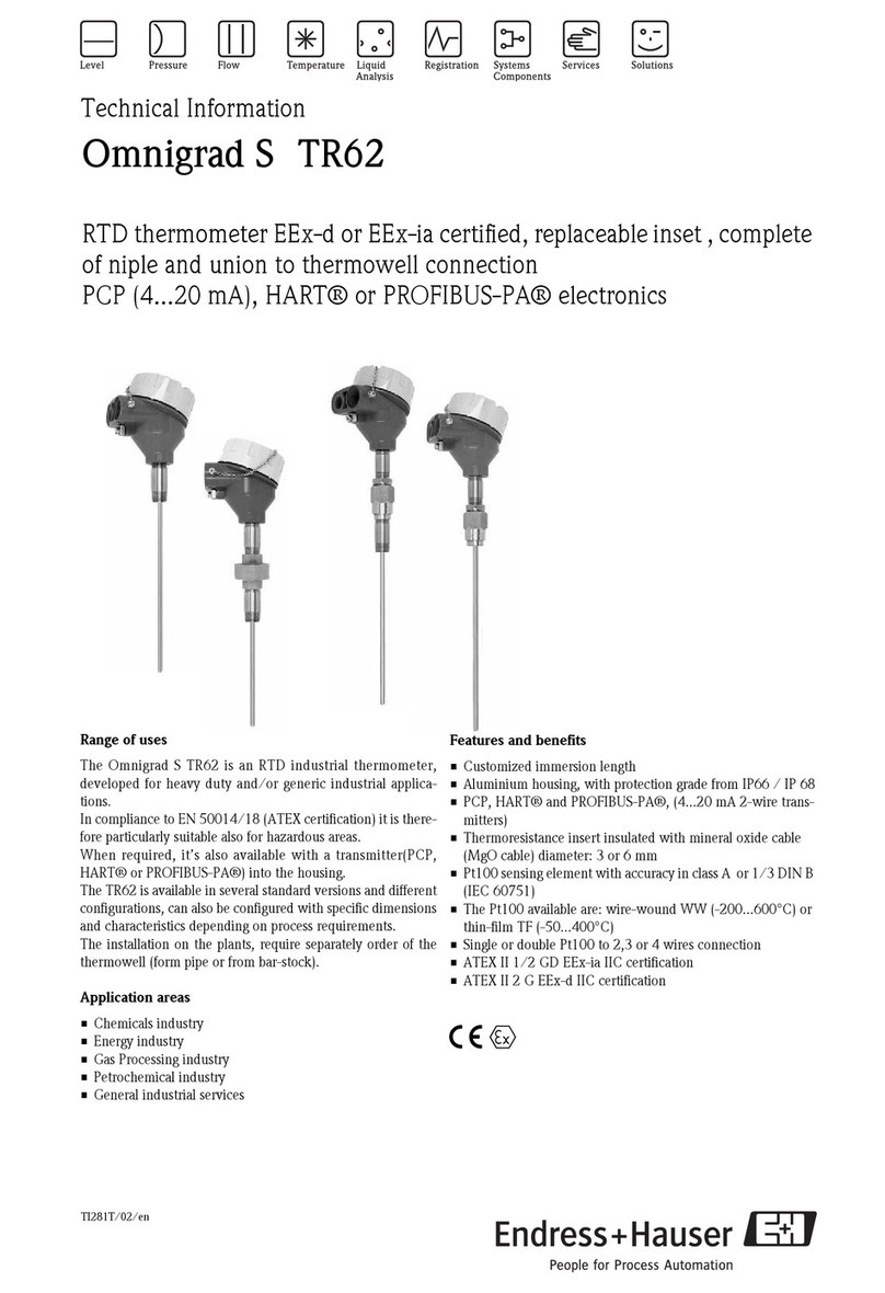
Endress+Hauser Omnigrad S TR62 Series Manual

Endress+Hauser
Endress+Hauser Omnigrad T TR25 Manual

Endress+Hauser
Endress+Hauser T 62 Series Installation instructions

Endress+Hauser
Endress+Hauser Omnigrad M TR13 Manual

Endress+Hauser
Endress+Hauser Prothermo NMT 539 User manual

Endress+Hauser
Endress+Hauser Omnigrad T TST310 Manual

Endress+Hauser
Endress+Hauser iTHERM TrustSens TM371 User manual

Endress+Hauser
Endress+Hauser Omnigrad TR1 Series Installation instructions