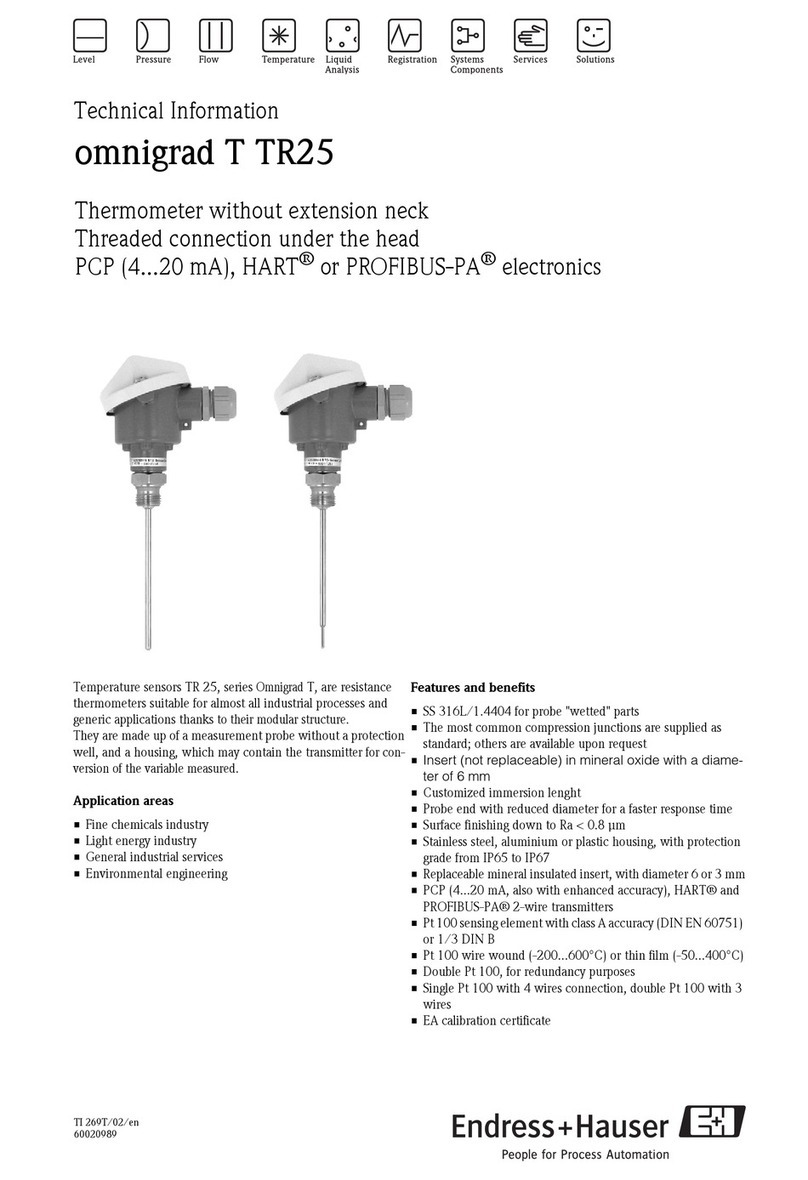
Endress+Hauser tmr31 User manual

Operating manual
Easytemp®TMR31, TMR35
BA215R/09/c4/03.08
71001719
de - Kompaktthermometer
en - Compact thermometer
fr - Capteur de température compact
it - Termometro compatto

2

3
; Kompaktthermometer Easytemp®TMR31, TMR35
Ka148-deutsch
Inhaltsverzeichnis
1 Sicherheitshinweise ........................................................................................................................ 3
2 Einbau............................................................................................................................................ 4
3 Verdrahtung auf einen Blick ............................................................................................................ 7
4 Inbetriebnahme .............................................................................................................................. 7
5 Bedienung ...................................................................................................................................... 8
6 Zubehör.......................................................................................................................................... 9
7 Rücksendung .................................................................................................................................. 9
8 Ergänzende Dokumentation.......................................................................................................... 10
1 Sicherheitshinweise
Bestimmungsge-
mäße Verwendung
Das Gerät ist ein Kompaktthermometer zur Erfassung und optionalen
Umformung von Temperatureingangssignalen für die industrielle Tempe-
raturmessung.
Der Hersteller haftet nicht für Schäden, die aus unsachgemäßer oder nicht
bestimmungsgemäßer Verwendung entstehen.
Montage, Inbetrieb-
nahme, Bedienung
Das Gerät darf nur von qualifiziertem und autorisiertem Fachpersonal (z.
B. Elektrofachkraft) unter strenger Beachtung dieser Anleitung, der ein-
schlägigen Normen, der gesetzlichen Vorschriften und der Zertifikate (je
nach Anwendung) eingebaut, angeschlossen und in Betrieb genommen
werden.
Das Fachpersonal muß diese Anleitung gelesen und verstanden haben und
die Anweisungen befolgen.
de
Ba215rde.fm Page 3 Monday, March 10, 2008 11:51 AM
4
Beschädigte Geräte dürfen nicht in Betrieb genommen werden und sind
als defekt zu kennzeichnen.
Betriebssicherheit Das Gerät ist nach dem Stand der Technik betriebssicher gebaut und
geprüft und hat das Werk in sicherheitstechnisch einwandfreiem Zustand
verlassen. Die einschlägigen Vorschriften und Euronormen sind berück-
sichtigt.
Beachten Sie die technischen Daten auf dem Typenschild!
Das Gerät darf nur von einem Netzteil mit energiebegrenztem Stromkreis
nach IEC 61010-1 gespeist werden: "SELV or Class 2 circuit".
Das Gerät ist aufgrund seines Aufbaus nicht reparierbar. Für eine spätere
Entsorgung beachten Sie bitte die örtlichen Vorschriften.
2 Einbau
Einbauhinweise Zulässige Umgebungstemperatur: -40 bis 85 °C (-40 bis 185 °F)
Prozesstemperaturgrenze:
– ohne Halsrohr: -50 bis 150 °C (-58 bis 302 °F)
– mit Halsrohr: -50 bis 200 °C (-58 bis 392 °F)
– ohne Transmitter: -50 bis 200 °C (-58 bis 392 °F)
Einschränkungen TMR31 in Abhängigkeit von der Umgebungstemperatur
(empfohlene Richtwerte):
de
max. Umgebungstemperatur max. Prozesstemperatur max. Prozesstemperatur mit Halsrohr
• bis 25 °C (77 °F)
• bis 40 °C (104 °F)
• bis 60 °C (140 °F)
• bis 85 °C (185 °F)
• 150 °C (302 °F)
• 135 °C (275 °F)
• 120 °C (248 °F)
• 100 °C (212 °F)
• 200 °C (392 °F)
• 180 °C (365 °F)
• 160 °C (320 °F)
• 133 °C (271 °F)
Ba215rde.fm Page 4 Monday, March 10, 2008 11:51 AM

5
Prozessdruckgrenze:
abhängig vom Prozessanschluss bis max. 100 bar (1450 PSI)
bei 20 °C (68 °F).
Einbauort
!Hinweis!
Mindesteinstecklänge Lmin = 40 mm (1.6 in)
TMR31 TMR35 (mit Prozessanschlussadapter)
• Pos. A: An Winkelstücken
• Pos. B: In kleineren Rohren, geneigt
• Pos. C: Senkrecht zur Strömungsrichtung
• L = Einstecklänge
Ba215rde.fm Page 5 Monday, March 10, 2008 11:51 AM
6
Einbau 1. Dichten Sie den Prozessanschluss (TMR31) mit Teflonband ab, bevor Sie
das Gerät einschrauben.
2. Stellen Sie sicher, dass die hygienischen Prozessanschlüsse (TMR35) und
die Anschlussadapter dem maximalen Prozessdruck standhalten.
"Achtung!
Bei Verwendung des Prozessanschlusses Prozessadapter G¾" muss der
Schweißprozess für den Einschweißadapter gemäß 3-A Anforderungen
durchgeführt werden. Die Schweißstelle muss nach Bedarf geschliffen
und poliert werden. Für weitere Informationen setzen Sie sich mit dem
Hersteller in Verbindung.
3. Bauen Sie das Gerät ein, bevor die Prozessanwendung gestartet wird.
4. Montieren Sie den M12-Stecker auf das Gerät und schließen Sie die
Spannungsversorgung entsprechend an (s. Kap. 3).
"Achtung!
Ziehen Sie den M12-Stecker nicht zu fest an, um Beschädigungen am
Gerät zu vermeiden.
Ba215rde.fm Page 6 Monday, March 10, 2008 11:51 AM

7
3 Verdrahtung auf einen Blick
Anschlussbelegung des 4-Leiter M12-Steckers für Ausgangssignal und Span-
nungsversorgung.
4 Inbetriebnahme
Nach Anlegen der Versorgungsspannung ist das Gerät im Messbetrieb.
• Pos. A: mit Messumformer, M12-Stecker, 4-polig
Pin 1: Spannungsversorgung 10 bis 35 V DC; 4 bis 20 mA (Kabelanschluss Adernfarbe braun = BN)
Pin 2: Anschluss PC-Konfigurationskabel - gekürzter Pin (Kabelanschluss Adernfarbe weiß = WH)
Pin 3: Spannungsversorgung 0 V DC; 4 bis 20 mA (Kabelanschluss Adernfarbe blau = BU)
Pin 4: Anschluss PC-Konfigurationskabel - gekürzter Pin (Kabelanschluss Adernfarbe schwarz = BK)
• Pos. B: ohne Messumformer, Pt100, 4-Leiter-Anschluss
Ba215rde.fm Page 7 Monday, March 10, 2008 11:51 AM
8
5 Bedienung
Die Konfiguration des Kompaktthermometers erfolgt unter Verwendung der
PC-Software ReadWin®2000, die im Konfigurationskit als Zubehör
(s. Kap. 6) erhältlich ist.
Ausführliche Informationen zur Konfiguration über ReadWin®2000 finden
Sie in der Online-Dokumentation der PC-Software.
Einstellbare Parameter
Standard-
einstellungen
• Messeinheit (°C/°F)
• Messbereichsgrenzen
-50 bis 150 °C (-58 bis 302 °F) ohne Halsrohr
-50 bis 200 °C (-58 bis 392 °F) mit Halsrohr
Erweiterte
Einstellungen
• Fehlerverhalten
• Ausgang (analog standard/invers)
• Filter (0 ... 8 s)
• Offset (-9,9 bis +9,9 K)
• Messstellenbezeichnung/TAG
Servicefunktionen • Simulation (ein/aus)
Ba215rde.fm Page 8 Monday, March 10, 2008 11:51 AM

9
6 Zubehör
Konfigurationskit (PC-Software ReadWin®2000 und Schnittstellenkabel
TTL/USB) für das Kompaktthermometer: Bestell-Code: TXU10-BA
ReadWin®2000 kann kostenlos direkt vom Internet unter folgender
Adresse geladen werden: www.endress.com/readwin
!Hinweis!
Ausführliche Informationen über weiteres Zubehör und Prozessanschlüsse
entnehmen Sie der Technischen Information (TI123R/09/de).
7 Rücksendung
Folgende Maßnahmen müssen ergriffen werden, bevor Sie ein Gerät an
Endress+Hauser zurücksenden:
Legen Sie dem Gerät in jedem Fall eine vollständig ausgefüllte “Erklärung
zur Kontamination” bei. Diese Erklärung befindet sich im Internet unter
www.endress.com/decontamination_form zum Download.
Entfernen Sie alle anhaftenden Messstoffreste. Dies ist besonders wichtig,
wenn der Messstoff gesundheitsgefährdend ist, z.B. brennbar, giftig,
ätzend, krebserregend, usw.
#Warnung!
Senden Sie keine Messgeräte zurück, wenn es Ihnen nicht mit letzter Sicher-
heit möglich ist, gesundheitsgefährdende Stoffe vollständig zu entfernen, z. B.
in Ritzen eingedrungene oder durch Kunststoff diffundierte Stoffe.
Ba215rde.fm Page 9 Monday, March 10, 2008 11:51 AM

10
8 Ergänzende Dokumentation
Weitere technische Daten:
Technische Information Easytemp®TMR31, TMR35 (TI123R/09/de)
PDF-Download unter: www.endress.com
Ba215rde.fm Page 10 Monday, March 10, 2008 11:51 AM
11
<Compact Thermometer Easytemp®TMR31, TMR35
Ka148-english
Table of contents
1 Safety instructions......................................................................................................................... 11
2 Installation ................................................................................................................................... 12
3 Wiring overview ........................................................................................................................... 16
4 Commissioning ............................................................................................................................ 16
5 Operation ..................................................................................................................................... 17
6 Accessories ................................................................................................................................... 17
7 Return .......................................................................................................................................... 18
8 Documentation............................................................................................................................. 18
1 Safety instructions
Designated use The device is a compact thermometer for the acquisition and optional
conversion of temperature input signals for industrial temperature
measurement.
The manufacturer is not liable for damage caused by improper or non-
designated use.
Installation,
commissioning,
operation
The device must only be installed, connected and commissioned by
qualified and authorized expert staff (e.g. electrical technicians) strictly
adhering to the instructions contained in this manual, the applicable
norms, legal regulations and certificates (depending on the application).
These experts must have read and understood this manual and follow the
instructions it contains.
en

12
Damaged devices must not be put into operation and they must be labeled
as defective.
Operational safety The device is safely built and tested according to state-of-the-art
technology and has left the factory in perfect condition as regards technical
safety. The applicable regulations and European standards have been taken
into account.
Please observe the technical data on the nameplate!
The device must only be powered by a power supply unit with a limited
energy electric circuit in accordance with IEC 61010-1: "SELV or Class 2
circuit".
Due to its design, the device is not repairable. When later disposing of the
device, please observe the local regulations.
2 Installation
Installation
instructions
Permitted ambient temperature range: -40 to 85 °C (-40 to 185 °F)
Process temperature limits:
– without extension neck: -50 to 150 °C (-58 to 302 °F)
– with extension neck: -50 to 200 °C (-58 to 392 °F)
– without transmitter: -50 to 200 °C (-58 to 392 °F)
en

13
Restrictions of TMR31 subject to the ambient temperature (recommended
guideline values):
Process pressure limits:
depending on the process connection, up to max. 100 bar (1450 PSI) at
20 °C (68 °F).
Max. ambient temperature Max. process temperature Max. process temperature with extension neck
• up to 25 °C (77 °F)
• up to 40 °C (104 °F)
• up to 60 °C (140 °F)
• up to 85 °C (185 °F)
• 150 °C (302 °F)
• 135 °C (275 °F)
• 120 °C (248 °F)
• 100 °C (212 °F)
• 200 °C (392 °F)
• 180 °C (365 °F)
• 160 °C (320 °F)
• 133 °C (271 °F)

14
Mounting location
!Note!
Minimum insertion length Lmin = 40 mm (1.6 in)
TMR31 TMR35 (with process connection adapter)
• Pos. A: On angle brackets
• Pos. B: In smaller pipes, inclined
• Pos. C: Perpendicular to the direction of flow
• L = Insertion length

15
Installation 1. Seal the process connection (TMR31) with Teflon tape before you screw
in the device.
2. Ensure that the hygienic process connections (TMR35) and the
connection adapters can withstand the maximum process pressure.
"Caution!
If the process connection process adaptor G¾" is used, the welding process
for installing the welding adaptor is conducted according to 3-A
requirements and ground and polished as necessary. Contact the
manufacturer for further information if required.
3. Install the device before the process application is started.
4. Fit the M12 plug onto the device and connect the power supply
accordingly (see chap. 3).
"Caution!
Do not tighten the M12 plug too much, in order to prevent damage to the
device.

16
3 Wiring overview
Pin assignment of the 4-wire M12 plug for output signal and power supply.
4 Commissioning
Once the supply voltage is applied, the device is in operation.
• Pos. A: with transmitter, M12 plug, 4-pin
Pin 1: power supply 10 to 35 V DC; 4 to 20 mA (cable connection, wire color brown = BN)
Pin 2: connection of PC configuration cable - shortened pin (cable connection, wire color white = WH)
Pin 3: power supply 0 V DC; 4 to 20 mA (cable connection, wire color blue = BU)
Pin 4: connection of PC configuration cable - shortened pin (cable connection, wire color black = BK)
• Pos. B: without transmitter, Pt100, 4-wire connection

17
5 Operation
The configuration of the compact thermometer is performed using the PC
software ReadWin®2000, which is available in the configuration kit as an
accessory (see page 17).
Detailed information about configuration using ReadWin®2000 can be found
in the online documentation of the PC software.
6 Accessories
Configuration kit (PC software ReadWin®2000 and interface cable TTL/
USB) for the compact thermometer: Order code: TXU10-BA
ReadWin®2000 can be downloaded free of charge on the Internet at the
following address: www.endress.com/readwin
Settable parameters
Standard settings • Measuring unit (°C/°F)
• Measuring range limits
-50 to 150 °C (-58 to 302 °F) without extension neck
-50 to 200 °C (-58 to 392 °F) with extension neck
Advanced settings • Fault condition reaction
• Output (analog standard/inverse)
• Filter (0 ... 8 s)
• Offset (-9.9 to +9.9 K)
• Measurement point identification/Tag
Service functions • Simulation (on/off)

18
!Note!
Detailed information about other accessories and process connections can be
found in the Technical Information (TI123R/09/en).
7 Return
The following procedures must be carried out before a device is returned to
Endress+Hauser:
Always enclose a fully completed “Declaration of Contamination” form
with the device. This declaration form can be downloaded from the
internet at www.endress.com/decontamination_form.
Remove all fluid residues. This is particularly important if the fluid is
hazardous to health, e.g. flammable, toxic, caustic, carcinogenic, etc.
#Warning!
Do not return a measuring device if you are not absolutely certain that all
traces of hazardous substances have been removed, e.g. substances which
have penetrated crevices or diffused through plastic.
8 Documentation
More technical data:
Technical Information Easytemp®TMR31, TMR35 (TI123R/09/en)
PDF download at: www.endress.com

19
=Capteur de température compact Easytemp®TMR31, TMR35
Ka148-deutsch
Sommaire
1 Conseils de sécurité ..................................................................................................................... 19
2 Montage ...................................................................................................................................... 20
3 Câblage en bref............................................................................................................................. 23
4 Mise en service............................................................................................................................. 23
5 Configuration............................................................................................................................... 24
6 Accessoires .................................................................................................................................. 25
7 Retour de matériel ........................................................................................................................ 25
8 Documentation complémentaire.................................................................................................... 26
1 Conseils de sécurité
Utilisation conforme L'appareil est un capteur de température compact destiné à la mesure et à
la conversion optimale de signaux d'entrée de température pour l'indus-
trie.
La garantie du fabricant ne couvre pas les dommages résultant d'une utili-
sation non conforme à l'objet.
Montage, mise en
service et configura-
tion
L'appareil ne doit être monté, raccordé et mis en service que par un per-
sonnel qualifié et autorisé (par ex. électrotechnicien), qui respectera stric-
tement le présent manuel, les normes en vigueur, les directives légales et
les certificats (selon l'application).
Le personnel spécialisé aura lu et compris le présent manuel et en suivra
les recommandations.
fr

20
Les appareils endommagés ne doivent pas être mis en service et sont à
marquer comme défectueux.
Sécurité de
fonctionnement
L'appareil a été construit selon les dernières évolutions techniques; il a été
testé et a quitté nos établissements dans un état technique parfait. Les
directives et normes européennes en vigueur ont été respectées.
Tenir compte des données techniques sur la plaque signalétique !
L'appareil ne doit être alimenté que par un circuit de courant limité en
énergie selon CEI 61010-1 : "SELV ou Class 2 circuit".
Du fait de sa construction l'appareil ne peut pas être réparé. Tenir compte
des directives locales en vigueur en cas de mise au rebut.
2 Montage
Conseils de
montage
Température ambiante admissible : -40 à 85 °C (-40 à 185 °F)
Limites de température du process :
–sans extension : -50 à 150 °C (-58 à 302 °F)
–avec extension : -50 à 200 °C (-58 à 392 °F)
–sans transmetteur : -50 à 200 °C (-58 à 392 °F)
Limitations TMR31 en fonction de la température ambiante
(valeurs indicatives) :
fr
Température ambiante max. Température de process max. Température de process. max. avec extension
• jusqu'à 25 °C (77 °F)
• jusqu'à 40 °C (104 °F)
• jusqu'à 60 °C (140 °F)
• jusqu'à 85 °C (185 °F)
• 150 °C (302 °F)
• 135 °C (275 °F)
• 120 °C (248 °F)
• 100 °C (212 °F)
• 200 °C (392 °F)
• 180 °C (365 °F)
• 160 °C (320 °F)
• 133 °C (271 °F)
Other manuals for tmr31
1
This manual suits for next models
1
Table of contents
Languages:
Other Endress+Hauser Thermometer manuals

Endress+Hauser
Endress+Hauser Omnigrad M TR13 Manual

Endress+Hauser
Endress+Hauser T13 Installation instructions

Endress+Hauser
Endress+Hauser Omnigrad TR1 Series Installation instructions

Endress+Hauser
Endress+Hauser iTHERM TrustSens TM372 User manual

Endress+Hauser
Endress+Hauser Omnigrad T TST310 Manual

Endress+Hauser
Endress+Hauser iTHERM TM411 Manual

Endress+Hauser
Endress+Hauser iTHERM CompactLine TM311 User manual

Endress+Hauser
Endress+Hauser Prothermo NMT 539 User manual

Endress+Hauser
Endress+Hauser tmr31 User manual

Endress+Hauser
Endress+Hauser Omnigrad S TR62 Series Manual