Energenics 007 User manual

1
www.energenics.com
1470 Don Street •Naples, Florida 34104 Telephone: (239) 643-1711
Fax: (239) 643-6081
Customer Service: (800) 944-1711
Installation & Operation Manual
For ENERGENICS 007 Control
In-Line Space Saver Lint Filters
Descriptions Page
Table of Contents 1
Description of Lint Filter Operation 2
Receiving and Installation 3
Important Installation Considerations 4
Warnings/Cautions 5
Dimensional Table 6
Dimensional Drawing 7
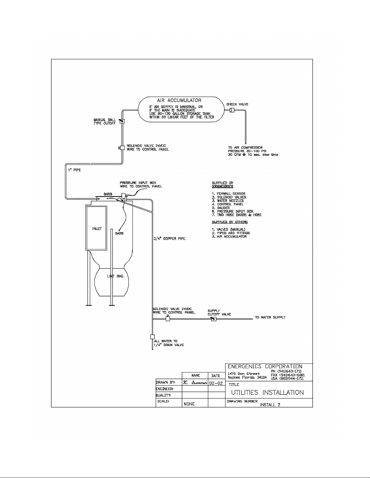
Utilities Installation 8
Sheet Metal Installation 9
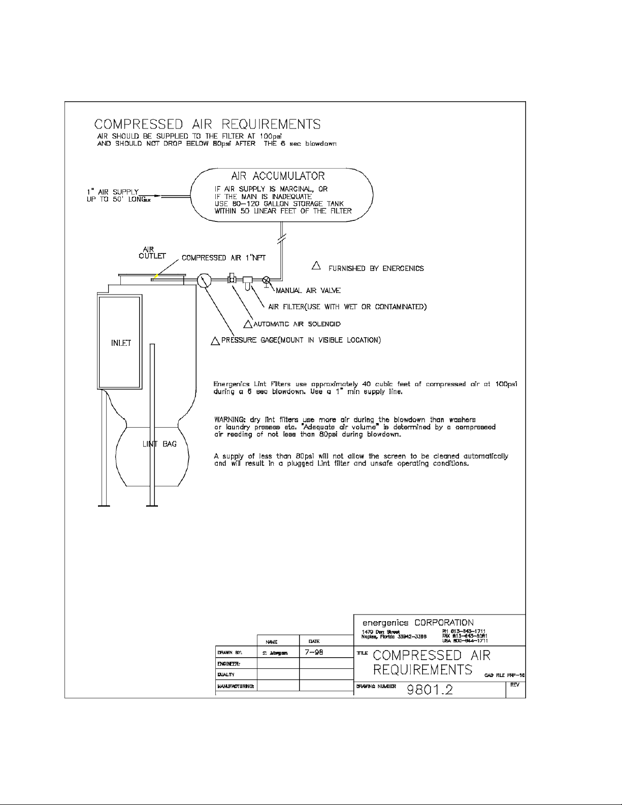
Compressed Air Requirements 10
Fire Suppression Water System (optional) 11
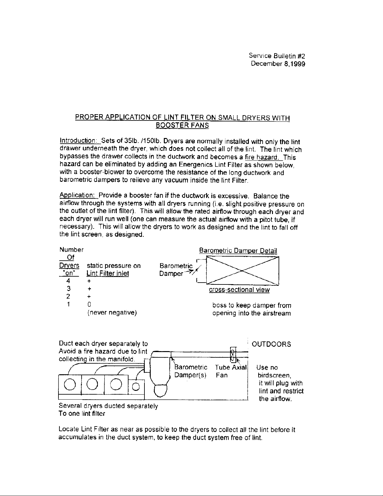
Proper Application with Booster Fans & Barometric Dampers 12
007 Control Installation Instructions:
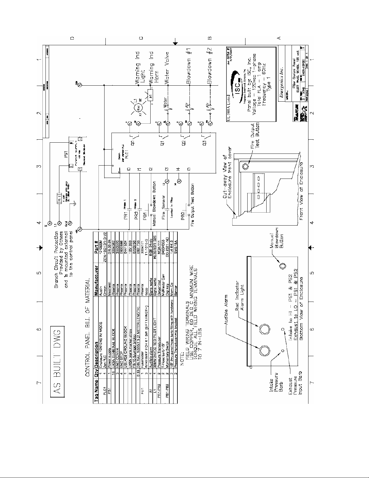
UL®Control Schematic & Wiring Diagram 13
Connection Requirement 9002.5 14
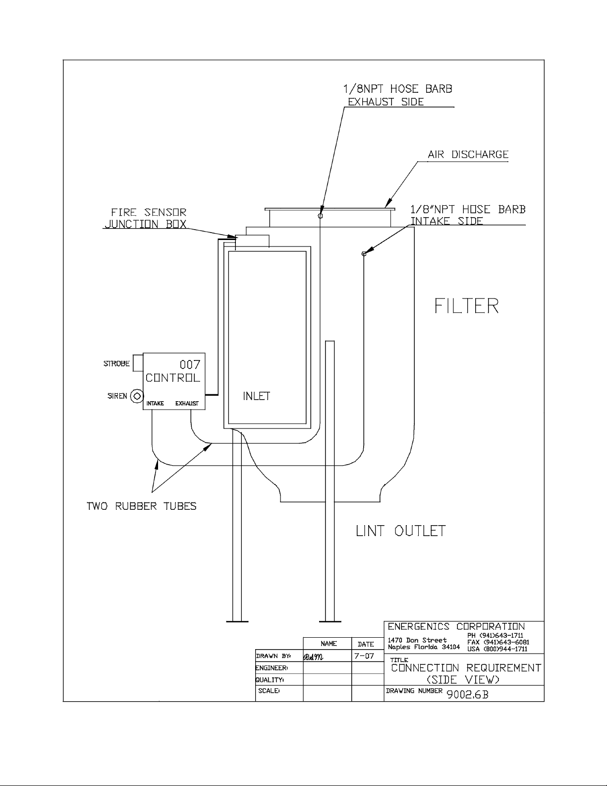
Connection Requirement (Side View) 9002.6 15
Maintenance Requirements 16

2
DESCRIPTION OF LINT FILTER OPERATION
Your new Energenics Lint Filter operated with a UL approved control represents
the most advanced features available in the laundry industry to date. The
following list the functions and mode of operation:
Blowdown (cleaning) –The Lint Filter will monitor the system backpressure and
automatically initiate the blowdown cycle. As the screen loads with lint the lint,
the back pressure will increase and will result in an automatic blowdown
(cleaning) when the backpressure reaches a set reference (default is .5” w.c.).
The lint filter will also blowdown every 30 minutes to insure complete screen
cleaning when dryers are turned off. The setting can be adjusted by the operator
by changing program values in the PLC. 70% of the lint will be removed from the
screen even though the dryer(s) may be operating. During the timed blowdown
with dryers off,100% of the lint will be removed from the screen. A manual
blowdown can also be done by depressing the button on the bottom of the Lint
Filter control. Note that automatic blowdown cannot occur within 3 minutes
of a prior blowdown. This is done to allow the compressed air supply to fully
recover.
Optional Excess Pressure Alarm –If for any reason the Lint Filter has not blown
down properly (i.e.: compressor turned off) the system will sense a higher
backpressure than normal. The excess light on the filter control and the siren
and the strobe light both activate. The Filter control will attempt to blowdown
every 3 minutes until the excess backpressure condition has terminated. If this
condition persist a manual inspection of the lint screen and observation of proper
blowdown must be done.
Optional Fire Control System –A normally open sensor located inside of the filter
at the top of the inlet will close at 360 degrees F. The control will open the water
solenoid, illuminate the strobe as well as energize the siren. The Alarm will be
active until 30 seconds after the temperature has dropped bellow 360 degrees F.
After 30 seconds the alarm will automatically reset. Inside the control box is a
Fire Control test button. Depress the button and the Fire Control will be activated
for 30 seconds. The function of the test button is to check the circuit. It does not
test the sensor itself. Using a propane torch to the sensor will test the complete
system.

3
Receiving and Installation
Before you sign the Bill of Lading:
1. Receiving-Inspect units inside and out for signs of damage
Verify all components are delivered per the Bill of Materials.
Report damage to the carrier IMMEDIATELY.
Note ALL damage on the Bill of Lading.
This is your responsibility and you must file all claims.
The filter is fully assembled and ready for installation. The
control, valves, and lint bag are in the cardboard box.
2. Installation-Follow instructions herein:
Determine the location with reference to minimum duct work from the dryer
and ease of access for inspection.
If using a lint drop pipe allow enough room for lint to travel down 4’ before the
first bend. Max bend angle is 30 degrees.
If using lint bag or container make sure adequate clearance is allowed.
Conduit or Sealtight between filter junction boxes should be ¾ inch.
Dependant on options ordered, not all outputs will have connected
components.
If the Fire ControlOption is NOT ordered the installer must supply a junction
box to connect the wires from the solenoid valve to the Control Box.
When mounting the filter overhead, mount the control below the filter where it
can be easily accessed.

4
Important Installation Considerations
All Energenics Lint Collectors can be mounted indoors or outdoors. If it is
mounted outdoors we recommend our Side Discharge or a field installed swept
radius elbow (Gooseneck). Do not use a conical cap on the filter exhaust
discharge. All solenoid valves should be located inside the building. Also, mount
the supplied air pressure gauge at the blowdown pipe on top of the filter.
All solenoids should be mounted as close to the filter as possible, but ALWAYS
inside the building. This will allow most of the air and water (if equipped with
optional Fire Control) piping to remain pressure charged for most efficient
operation.
All wiring should be a minimum of 18 gage for proper operation.
The Filter Control box should be located in a position to be easily seen and in
close proximity to personnel. In other words if the Filter Control is located
outdoors, 20 feet in the air or in another room away from the laundry personnel,
this would be the wrong location. Lint Filter controls should never be mounted
outdoors.
Since the Filter uses compressed air it is important that the air receiver (if
equipped) be located as close to the filter as possible. The longer the pipe runs
the more restrictive. You will need to increase the pipe diameter if the run is very
long (e.g.: 60 feet).
If the installation is a multi-dryer/multi-duct installation it may be necessary to use
backdraft dampers to prevent lint backflow into the ducts of turned off dryers.
Most dryers have them available as standard equipment or can be ordered to
add on.
After everything is mounted and utilities turned on press the manual blowdown
button located on the bottom of the Filter Control. The rotor on the inside the lint
filter should spin. Make sure that the air pressure at the filter starts out at 100
and ends at about 60 at the end of the blowdown cycle. If it is too low the rotor
won’t turn.
If the Filter is equipped with Fire Suppression,the test button is on the inside of
the Filter Control. It is on the inside to keep people from pushing the button as
they walk by. When the button is pushed the strobe and siren will go on along
with the water solenoid valve. The system operates until the button is no longer
depressed.

5
Warning and Caution
You have purchased the finest lint filter available for your facility. Please follow
these instructions to ensure a safe long life for your filter and facility.
FAILURE TO FOLLOW THESE INSTRUCTIONS CAN RESULT IN
AN UNSAFE OPERATING CONDITION, INCLUDING THE
POSSIBILITY OF FIRE.
DO NOT OPERATE ANY DRYER CONNNECTED TO THIS FILTER
WITHOUT BEING CERTAIN THE FILTER STARTUP HAS BEEN
COMPLETED AND THE FILTER IS IN OPERATING CONDITION.
Insure it is installed in compliance with local codes.
Step 1. Install the compressed air (Fire suppression plumbing if ordered), and
piping system(s) including solenoid valves. If the filter is in position,
make all final connections.
Step 2. Mount the 007 control in a visible location on a solid vibration free
surface and connect all components.
Step 3. Provide dedicated electrical service to the transformer and test all
systems.
Step 4. Install sheet metal and ducting.
START UP AND OPERATION INSTRUCTIONS
Inspect the filter installation. Is it complete? Review the entire installation
requirements prior to startup.
1. Verify the 007 control wiring.
2. Test the blow down cycle (push manual button on control).
Watch the pressure gauge. It should start at 100psi and should not drop below
80psi during the 6-10 second cycle.
The rotor should turn 6-12 times during blow down. The rotor propulsion is
adjustable by increasing the number of horizontal holes on the top horizontal
portion of the rotor end.
3. Review maintenance requirements and establish a regular PM schedule.
CAUTION -DO NOT OPERATE FILTER WITH BOOSTER
FAN WITHOUT BAROMETRIC DAMPER!!!!!!!!
(CONSULT PAGE 12)

6

7
8

9
10

11
12
13

14
15

16
Maintenance Requirements
The frequency of your maintenance requirements depends upon the number of hours of
operation and upon variances in your product output. For a single-shift operation,
without special problems, the frequency recommended below should suffice. You
should set your own schedule based on your experience.
1. WEEKLY
Visually inspect the filter inside and outside, its controls and their operation. At time of such
inspection, note and correct any discrepancies from normal operation.
2. MONTHLY
Check the static pressure. Disconnect the lower pressure hose, and then use a magnehelic
gauge, manometer, or U-tube to measure and record the resistance. This will show the pattern
of operation of your system. If pressure exceeds 1 inch W.C., insure the rotor is correctly
turning and cleaning the screen.
Watch the air pressure gauge on the filter. Record the drop in pressure during the blow down
cycle. A normal pressure is from 100psi at the start to 80psi after six seconds. The minimum
pressure is 80psi. Any less will not reliably clean the screen. If the pressure were to fall from
100psi to 40psi, the air supply is inadequate or obstructed.
3. QUARTERLY
On filters using fire protection control, carefully test the Fenwall fire sensor accessed through
the inspection door. First disconnect the initiator/solenoid leads from the panel and connect a
24 VDC bulb to initiator terminals in the control unit. Heat the Fenwall fire sensor with a
heat lamp or other convenient source. When the bulb in the control unit changes state,
remove heat source and allow Fenwall fire sensor to cool. Reset control unit. Test lamp must
change state and stay changed after system is reset. Do not reconnect initiator/solenoid leads
until all Fenwall fire sensors have cooled below set point as indicated by test lamp.
FILTER SCREEN MAINTENANCE
Chemicals present in the laundry uniforms, shop towels or other linen may eventually clog the
filter screen. When this occurs, try the following:
1. Spray with an engine degreaser like GUNK. Allow soaking per the instructions for
cleaning an auto engine. Spray clean with water.
2. Operate one dryer without a load to blow hot air through the filter to dry it.
3. Restart the dryer. Operation should be perfectly normal. It should not be necessary to
replace the screen unless it is punctured.
Table of contents
Other Energenics Laboratory Equipment manuals


