manuals.online logo
Brands
  1. Home
  2. •
  3. Brands
  4. •
  5. Energetic Lighting
  6. •
  7. Lighting Equipment
  8. •
  9. Energetic Lighting E1WPB Series User manual

Energetic Lighting E1WPB Series User manual

1
LED Full-Cutoff Wall Pack
Installation Instructions
Model # E1WPB series
Questions, problems, missing parts? Before returning to your retailer, call our customer
service department at 1-866-492-6566.
Item Number Purchase Date
ATTACH YOUR RECEIPT HERE
www.energeticlighting.com
LIGHTING
This equipment has been tested and found to comply with the limits for a Class B digital
device, pursuant to part 15 of the FCC Rules. These limits are designed to provide
reasonable protection against harmful interference in a residential installation. This
equipment generates, uses and can radiate radio frequency energy and, if not installed and
used in accordance with the instructions, may cause harmful interference to radio or
television reception, which can be determined by turning the equipment off and on. The
user is encouraged to try to correct the interference by one or more of the following
measures:
Reorient or relocate the receiving antenna.
Increase the separation between the equipment and the receiver.
Connect the equipment into an outlet on a circuit different from that to which the receiver is
connected.
Consult the dealer or an experienced radio/TV technician for help.
This Class B digital apparatus complies with Canadian ICES-003.
32
•
-
-
-
-
•
Please read and understand this entire manual before attempting to assemble, operate or
install the product. Failure to do so could lead to electric shock, fire or other injuries that
could be hazardous or even fatal.
Be sure the electricity to the wires you are working on is shut off. Either remove the fuse or
turn off the circuit breaker.
Changes or modifications not expressly approved by the party responsible for compliance
could void the user’s authority to operate the equipment.
This product must be installed in accordance with local, state and national electrical codes.
Installation work shall be completed by a licensed installer that is familiar with the
construction and operations of the product.
CAUTION:
The fixture body is one piece. Do not disassemble it.
This product can NOT be dimmed, do not installed in a dimming switch circuit.
NOTICE
This device complies with Part 15 of the FCC Rules. Operation is subject to the following
two conditions: (1) This device may not cause harmful interference, and (2) this device
must accept any interference received, including interference that may cause undesired
operation.
Before beginning assembly of product, make sure all parts are present. Compare parts with
package contents list and hardware contents list. If any part is missing or damaged, do not
attempt to assemble the product.
Estimated Assembly Time: 20 minutes.
Tools Required for Assembly (not included): Phillips screwdriver, flathead screwdriver, safety
glasses.
To ensure a safe and proper installation, an assistant should be available during the installation
to support the fixture assembly while work is performed during mounting and wiring of the
fixture. Before begining installation, ensure that power is disconnected to the supply wires.
•
•
•
•
•
•
•
1. Remove the retaining screw (C) from the bottom of
the fixture body (A) and set aside. Separate the back
plate (B) from the fixture body (A).
www.energeticlighting.com www.energeticlighting.com
Part Item Name Qty.
AFixture Body 1
BBack Plate (Preassembled to A) 1
CRetaining Screw (Preassembled to A) 1
PACKAGE CONTENTS
SAFETY INFORMATION
SAFETY INFORMATION
HARDWARE CONTENTS
PREPARATION
INSTALLATION INSTRUCTIONS
Fig. 1
AA
Wire Nuts
Qty. 3
Junction Box
Screws
Qty. 4
BB
B
B
C
C
1
2
A
A
4
This fixture is warranted to perform free from defects for five years. If it fails to do so, you may
return it with proof of purchase to 13445 12th St., Chino, CA 91710 for replacement.
Clean with a mild, non-abrasive glass cleaner and soft cloth. Do NOT use solvents or clean-
ers containing abrasive agents. When cleaning the fixture, make sure the power is turned
off, and any liquid spray should be applied to the cleaning cloth and not sprayed directly onto
the fixture itself.
www.energeticlighting.com
INSTALLATION INSTRUCTIONS INSTALLATION INSTRUCTIONS
CARE AND MAINTENANCE
TROUBLESHOOTING
WARRANTY
Problem Possible Solution Corrective Action
Fixture does not light.
Circuit breaker trips
when light is turned on.
1. Power is off.
2. Incorrect wire connection.
3. Defective wall switch.
Crossed wires or power
wire is grounded out.
Verify wires are correctly
connected.
1. Check circuit breaker
or wall switch.
2. Check wire splices.
3. Replace switch.
2. Prior to mounting the back plate to the mounting
surface, apply silicon sealant (not provided) around
the perimeter of the junction box to seal out water
from entering the wiring compartment. Align the back
plate (B) with the junction box so that the back plate is
flush against the mounting surface and the tabs are
located in the upward direction. Route the supply
wires from the junction box through the center
opening of the back plate (B).
Fig. 2
4. Tuck the wires and wire nuts into the junction box and
align the back plate (B) tabs with the support notches
on the mating face of the fixture body (A). Angle the
fixture body so that the top edge of the tabs enter the
notches first and once fully seated rotate the body
down until it sits flush against the back plate and
mounting surface. Ensure that the fixture is fully
supported by the back plate before releasing the
fixture from your hands.
Fig. 4
AA
3. Apply more silicon sealant around the mating edges
of the body to the mounting surface and back plate to
seal out the elements from the wiring campartment.
Hold the fixture up to the mounted back plate (B) and
connect the supply wires to the fixture wires -- black
to black, white to white, and green to copper/bare.
WARNING: If there is no ground supply wire, stop
installation and consult a qualified electrician.
Once wire connections are made, secure each with a
wire nut (AA).
Fig. 3
5
Printed in China
www.energeticlighting.com
5. Reinstall the retaining screw (C) back into the bottom
of the fixture body (A) and check to ensure that the
fixture body is locked in place before completing the
installation.
Fig. 5
Seal with
silicone
sealant
Seal with
silicone
sealant
A
C
B
B
BB
Back Plate Tabs up
A

Other Energetic Lighting Lighting Equipment manuals

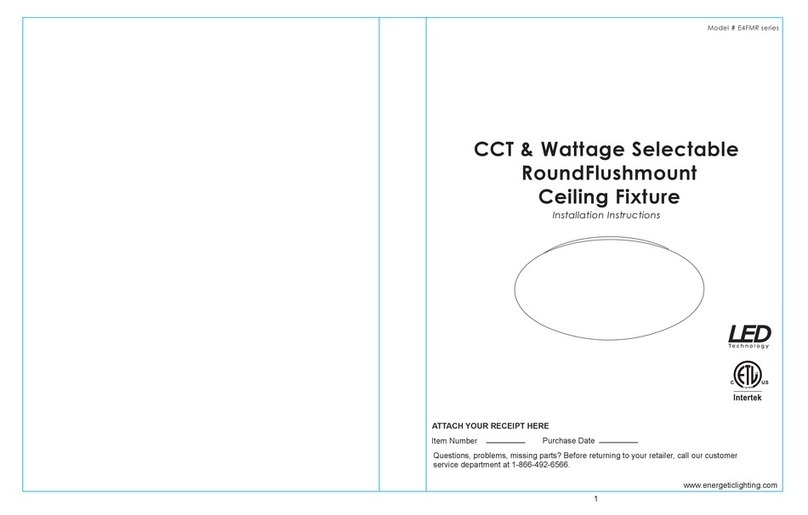
Energetic Lighting E4FMR Series User manual

Energetic Lighting

Energetic Lighting E4FMR Series User manual

Energetic Lighting E1WPA Series User manual

Energetic Lighting

Energetic Lighting E1WPA Series User manual

Energetic Lighting E1ALB30 User manual

Energetic Lighting

Energetic Lighting E1ALB30 User manual

Energetic Lighting E1ALB Series User manual

Energetic Lighting

Energetic Lighting E1ALB Series User manual

Energetic Lighting ELYRTD Series User manual

Energetic Lighting

Energetic Lighting ELYRTD Series User manual

Energetic Lighting E2FMA Series User manual

Energetic Lighting

Energetic Lighting E2FMA Series User manual

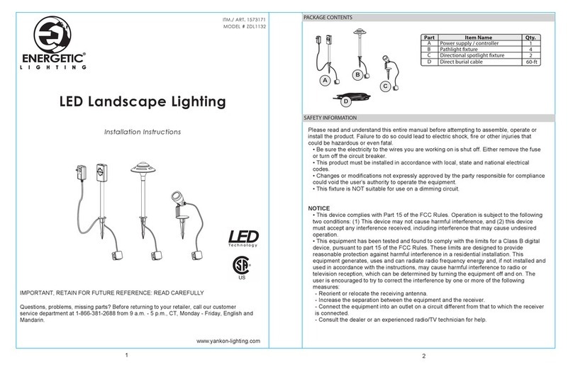
Energetic Lighting ZDL1132 User manual

Energetic Lighting

Energetic Lighting ZDL1132 User manual

Energetic Lighting E2WPA Series User manual

Energetic Lighting

Energetic Lighting E2WPA Series User manual

Energetic Lighting E1PL Series User manual

Energetic Lighting

Energetic Lighting E1PL Series User manual

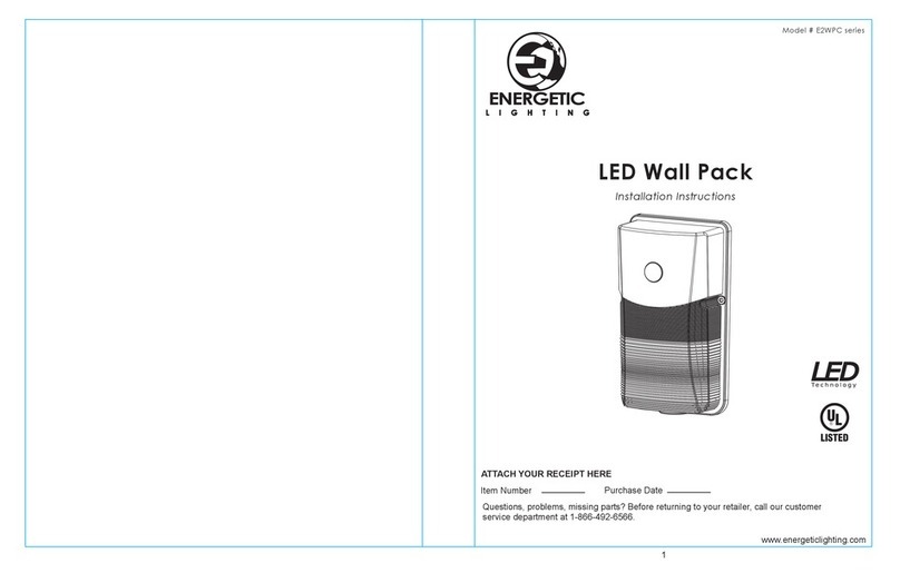
Energetic Lighting E2WPC Series User manual

Energetic Lighting

Energetic Lighting E2WPC Series User manual

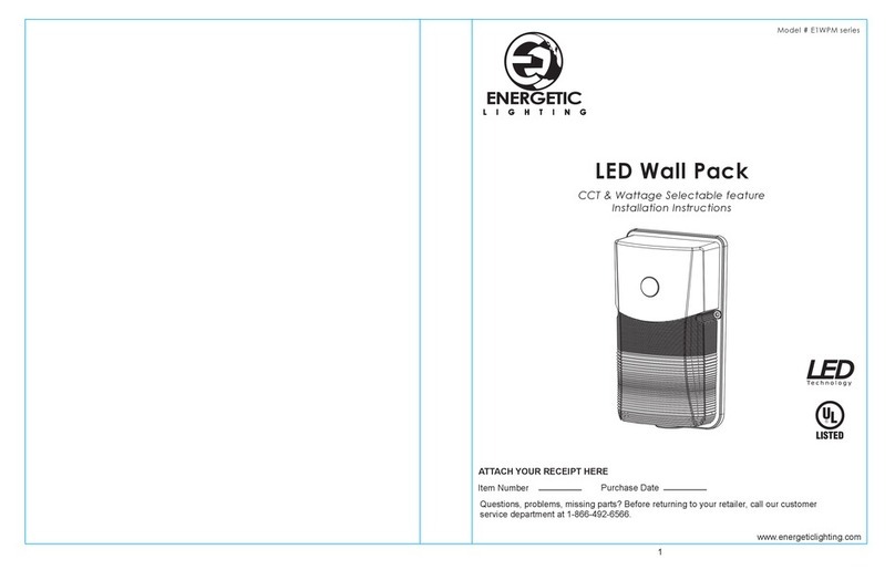
Energetic Lighting E1WPM Series User manual

Energetic Lighting

Energetic Lighting E1WPM Series User manual

Popular Lighting Equipment manuals by other brands

Loop-Loc Ultra Loc III Solid installation guide

Loop-Loc

Loop-Loc Ultra Loc III Solid installation guide

Cameo MOVO BEAM 200 user manual

Cameo

Cameo MOVO BEAM 200 user manual

MELINERA 279621 Operation and safety notes

MELINERA

MELINERA 279621 Operation and safety notes

Utilitech CMG-NYC-M3 installation instructions

Utilitech

Utilitech CMG-NYC-M3 installation instructions

Sagitter MOVING WASH 575 user manual

Sagitter

Sagitter MOVING WASH 575 user manual

SLV GIMBLE PRO operating manual

SLV

SLV GIMBLE PRO operating manual

JONATHAN Y JYL4007A instructions

JONATHAN Y

JONATHAN Y JYL4007A instructions

Robin Robin Cyclone user manual

Robin

Robin Robin Cyclone user manual

Lightolier LSBW-2 Specification sheet

Lightolier

Lightolier LSBW-2 Specification sheet

Williams-Sonoma Hayes Assembly instructions

Williams-Sonoma

Williams-Sonoma Hayes Assembly instructions

CLS MIKA Series manual

CLS

CLS MIKA Series manual

Coemar FX PROJECTOR user manual

Coemar

Coemar FX PROJECTOR user manual

JCM Technologies MICRO-FLASH Assembly and use instructions

JCM Technologies

JCM Technologies MICRO-FLASH Assembly and use instructions

PLG SIRIO PR user manual

PLG

PLG SIRIO PR user manual

Stairville DMX Joker V2 PRO NET quick start guide

Stairville

Stairville DMX Joker V2 PRO NET quick start guide

Elation UV WASH User instructions

Elation

Elation UV WASH User instructions

PROEL PLLAS115X2TWO RAYS user manual

PROEL

PROEL PLLAS115X2TWO RAYS user manual

Bresser PT PRO Series instruction manual

Bresser

Bresser PT PRO Series instruction manual

manuals.online logo
manuals.online logoBrands
  • About & Mission
  • Contact us
  • Privacy Policy
  • Terms and Conditions

Copyright 2025 Manuals.Online. All Rights Reserved.