manuals.online logo
Brands
  1. Home
  2. •
  3. Brands
  4. •
  5. Energetic Lighting
  6. •
  7. Lighting Equipment
  8. •
  9. Energetic Lighting E2WPC Series User manual

Energetic Lighting E2WPC Series User manual

1
LED Wall Pack
Installation Instructions
Model # E2WPC series
Questions, problems, missing parts? Before returning to your retailer, call our customer
service department at 1-866-492-6566.
Item Number Purchase Date
ATTACH YOUR RECEIPT HERE
www.energeticlighting.com
LIGHTING
This equipment has been tested and found to comply with the limits for a Class B digital
device, pursuant to part 15 of the FCC Rules. These limits are designed to provide
reasonable protection against harmful interference in a residential installation. This
equipment generates, uses and can radiate radio frequency energy and, if not installed and
used in accordance with the instructions, may cause harmful interference to radio or
television reception, which can be determined by turning the equipment off and on. The
user is encouraged to try to correct the interference by one or more of the following
measures:
Reorient or relocate the receiving antenna.
Increase the separation between the equipment and the receiver.
Connect the equipment into an outlet on a circuit different from that to which the receiver is
connected.
Consult the dealer or an experienced radio/TV technician for help.
This Class B digital apparatus complies with Canadian ICES-003.
32
•
-
-
-
-
•
Please read and understand this entire manual before attempting to assemble, operate or
install the product. Failure to do so could lead to electric shock, fire or other injuries that
could be hazardous or even fatal.
• Be sure the electricity to the wires you are working on is shut off. Either remove the fuse or
turn off the circuit breaker.
• Changes or modifications not expressly approved by the party responsible for compliance
could void the user’s authority to operate the equipment.
• This product must be installed in accordance with the applicable installation code by a
person familiar with the construction and operation of the product and the hazards involved.
CAUTION:
• This product can be dimmed using a 0-10v dimming system only, DO NOT use on circuit
with phase-cut triac type dimmer switches.
• Suitable for wet locations.
• Wall mount only.
NOTICE
• This device complies with Part 15 of the FCC Rules. Operation is subject to the following
two conditions: (1) This device may not cause harmful interference, and (2) this device must
accept any interference received, including interference that may cause undesired operation.
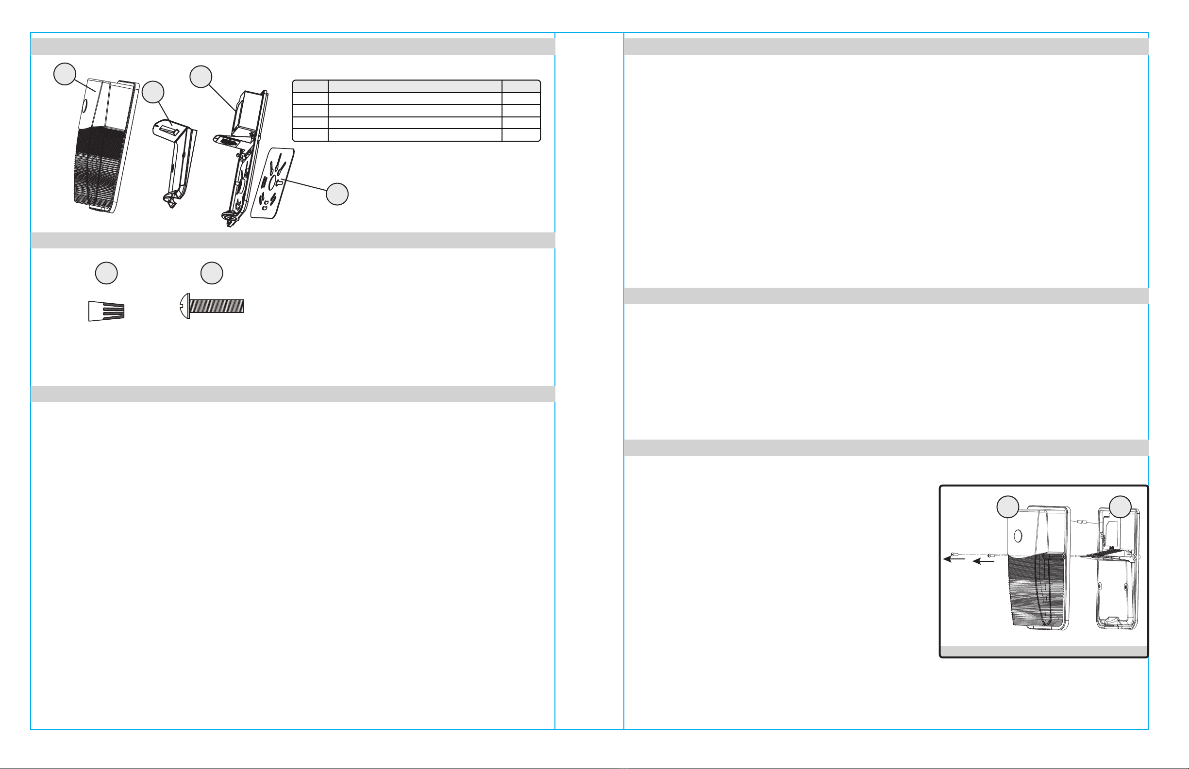
Before beginning assembly of product, make sure all parts are present. Compare parts with
package contents list and hardware contents list. If any part is missing or damaged, do not
attempt to assemble the product.
Estimated Assembly Time: 20 minutes.
Tools Required for Assembly (not included): Phillips screwdriver, flathead screwdriver, safety
glasses, power drill and bits.
To ensure a safe and proper installation, ensure that power is disconnected to the supply wires.
1. Remove the two screws on both sides of the fixture to
separate the front lens cover (A) and back plate (C).
www.energeticlighting.com www.energeticlighting.com
Part Item Name Qty.
ALens Front Cover 1
BReector 1
CBack Plate 1
DSilicone Gasket 1
PACKAGE CONTENTS
SAFETY INFORMATION
SAFETY INFORMATION
HARDWARE CONTENTS
PREPARATION
INSTALLATION INSTRUCTIONS
Fig. 1
AA
Wire Nuts
(Qty. 2 preassembled)
Qty. 5
B
C
D
A
CA
Junction Box
Screws
Qty. 4
BB
4
www.energeticlighting.com www.energeticlighting.com
INSTALLATION INSTRUCTIONS INSTALLATION INSTRUCTIONS
2. Disconnect the photocell wire connector and set aside
the lens front cover (A).
Fig. 2
5
3. Remove the three (3) screws in front of the reflector
(B) and set the screws and reflector aside.
Fig. 3
5. Hold up the fixture back plate (C) to the junction box
(not provided) and determine which set of slots line
up with the mounting screw pattern provided by the
junction box. For proper wet location install, ensure
that silicone gasket (D) is installed between back
plate (C) and mounting surface.
Ensure that power is shut off and
connect the supply
wires to the fixture wires -- black to black, white to
white, and green to copper/bare.
WARNING: If there is no ground supply wire, stop
installation and consult a qualified electrician.
Once wire connections are made, secure each with a
wire nut (AA).
Dimming Connection: If fixture is to be connected to
a dimming system, connect the purple and gray leads
to its corresponding 0-10v dimming supply leads.
Otherwise, leaving the fixture 0-10v dimming leads
open will enable the fixture to run at 100% lumen
output.
Fig. 5
6. Secure the fixture to the junction box using the
necessary junction box screws (BB) provided to
ensure proper mounting and seal around the junction
box.
Fig. 6
7. Retrieve reflector (B) and the thre screws previously
removed in step #3, and re-install the reflector (B)
onto the back plate (C).
Fig. 7
B
C
4. For proper installation in a wet location environment,
peel off each of the adhesive protective layers from
the silicone gasket (D) and line up the slot pattern to
the back plate (C) to create a seal when installed onto
the junction box in the next step.
Fig. 4
C
AA
C
C
BB
C
B
D
D
Peel o adhesive
cover layers
D
This fixture is warranted to perform free from defects for five years. If it fails to do so, you may
return it with proof of purchase to 13445 12th St., Chino, CA 91710 for replacement.
Clean with a mild, non-abrasive glass cleaner and soft cloth. Do NOT use solvents or clean-
ers containing abrasive agents. When cleaning the fixture, make sure the power is turned
off, and any liquid spray should be applied to the cleaning cloth and not sprayed directly onto
the fixture itself.
INSTALLATION INSTRUCTIONS
CARE AND MAINTENANCE
TROUBLESHOOTING
WARRANTY
Problem Possible Solution Corrective Action
Fixture does not light.
Circuit breaker trips
when light is turned on.
1. Power is off.
2. Incorrect wire connection.
3. Defective wall switch.
Crossed wires or power
wire is grounded out.
Verify wires are correctly
connected.
1. Check circuit breaker
or wall switch.
2. Check wire splices.
3. Replace switch.
6
Printed in China
www.energeticlighting.com
8. Replace the lens front cover (A) using the original 2
screws previously removed in step #1 to complete the
installation.
Fig. 8
CA

Other Energetic Lighting Lighting Equipment manuals

Energetic Lighting E1WPB Series User manual

Energetic Lighting

Energetic Lighting E1WPB Series User manual

Energetic Lighting E1WPM Series User manual

Energetic Lighting

Energetic Lighting E1WPM Series User manual

Energetic Lighting E1WPA Series User manual

Energetic Lighting

Energetic Lighting E1WPA Series User manual

Energetic Lighting ZDL1132 User manual

Energetic Lighting

Energetic Lighting ZDL1132 User manual

Energetic Lighting E1ALB Series User manual

Energetic Lighting

Energetic Lighting E1ALB Series User manual

Energetic Lighting E1ALB30 User manual

Energetic Lighting

Energetic Lighting E1ALB30 User manual

Energetic Lighting E4FMR Series User manual

Energetic Lighting

Energetic Lighting E4FMR Series User manual

Energetic Lighting ELYRTD Series User manual

Energetic Lighting

Energetic Lighting ELYRTD Series User manual

Energetic Lighting E2FMA Series User manual

Energetic Lighting

Energetic Lighting E2FMA Series User manual

Energetic Lighting E1PL Series User manual

Energetic Lighting

Energetic Lighting E1PL Series User manual

Energetic Lighting E2WPA Series User manual

Energetic Lighting

Energetic Lighting E2WPA Series User manual

Popular Lighting Equipment manuals by other brands

PT W2261 owner's manual

PT

PT W2261 owner's manual

FONESTAR BAR-73L instruction manual

FONESTAR

FONESTAR BAR-73L instruction manual

iSolution Xperior 700A Beam user guide

iSolution

iSolution Xperior 700A Beam user guide

Cameo OCTAFLY user manual

Cameo

Cameo OCTAFLY user manual

FINNSUB Short 750 user manual

FINNSUB

FINNSUB Short 750 user manual

Generay RGB Series user manual

Generay

Generay RGB Series user manual

BITEHARDER SHSL12V instructions

BITEHARDER

BITEHARDER SHSL12V instructions

Epoch Helios 980 operating instructions

Epoch

Epoch Helios 980 operating instructions

Griven PARADE D-RGB instruction manual

Griven

Griven PARADE D-RGB instruction manual

Vision & Control LDLF30x420-R633/24V/-a installation guide

Vision & Control

Vision & Control LDLF30x420-R633/24V/-a installation guide

THORLABS DC3100 Series Operation manual

THORLABS

THORLABS DC3100 Series Operation manual

Philips Hue 1822511 quick guide

Philips

Philips Hue 1822511 quick guide

Martin MAC 575 Krypton user manual

Martin

Martin MAC 575 Krypton user manual

Bresser BR-D1200BL instruction manual

Bresser

Bresser BR-D1200BL instruction manual

Original BTC DAVEY LIGHTING 7202 instruction manual

Original BTC

Original BTC DAVEY LIGHTING 7202 instruction manual

Excelitas Technologies XLED1 quick start guide

Excelitas Technologies

Excelitas Technologies XLED1 quick start guide

Larson Electronics VPLHL-15WLED-PC-GR30 instruction manual

Larson Electronics

Larson Electronics VPLHL-15WLED-PC-GR30 instruction manual

ACME DIABOLO 500 user manual

ACME

ACME DIABOLO 500 user manual

manuals.online logo
manuals.online logoBrands
  • About & Mission
  • Contact us
  • Privacy Policy
  • Terms and Conditions

Copyright 2025 Manuals.Online. All Rights Reserved.