manuals.online logo
Brands
  1. Home
  2. •
  3. Brands
  4. •
  5. ENFORCER
  6. •
  7. Power Supply
  8. •
  9. ENFORCER EVP-224D2-P4Q User manual

ENFORCER EVP-224D2-P4Q User manual

BEFORE CONNECTING TO CCTV CAMERAS OR DEVICES:
• Check the DIP switch setting to ensure correct voltage (6VDC, 12VDC, or 24VDC).
• With power turned on, check the wires connected to each terminal pair to ensure correct voltage.
EVP-224D4-P9QShown
•
Enclosure:
•
Heavy-duty steel case to protect the power connections
•
Removable steel cover for easy access
•
Ventilation holes to prevent heat build-up
•
Dimensions - 10” x 7.75” x 3.5” (254 x 196 x 89 mm)
[12.15" x 12.25" x 3.6" (308 x 311 x 91 mm) for
EVP-224D6P16Q]
•
Knock-out on the cover for optional cam lock
Specifications:
•
Adjustable VDC outputs:
•
Output voltage adjustable with potentiometer to
compensate for voltage drop.
•
Each individually fused (PTC**-type fuses)
•
Output fuses rated 1.1 Amps @ 250VAC
•
Individual red status indicator LED for each output
•
Main power switch to turn on/off power to outputs
•
Power:
•
Input:240VAC; Output: 6/12/24VDC
•
Main fuse rated 5.0 Amps @ 250VAC ( 3Amps. for
EVP-224D2-P4Q)
•
Spare fuse included
**Positive Temperature Coefficient
Installation Manual
ENFORCER ®
EVP-224D2-P4Q
(4 Outputs@ 6/12/24VDC, 2 Amps*)
EVP-224D4-P9Q
(9 Outputs@ 6/12/24VDC, 4 Amps*)
EVP-224D6P16Q
(16 Outputs @ 6/12/24VDC, 6 Amps*)
DC-Power Supplies for CCTV Cameras and Accessories
* Total max. supply current at 12VDC, each channel output is fused at 1.1 Amp.
Knock-out for
optional cam lock
Ventilation
Holes
FIG. 1: Knockouts
for running cables
Cable & Power
Knock-outs
What it is:
This ENFORCER CCTV power supply centralizes the CCTV system's power
input, power transformer, DC regulator, and independently-fused power
outputs in one heavy-duty, easy-to-install enclosure.
Note before installation:
•DOUBLE-CHECK VOLTAGE SETTINGS BEFORE CONNECTING THE CAMERAS.
•Indoor use only - Do not mount where exposed to rain or moisture.
•For professional installation only.
•Installation must conform to all local codes.
Installation:
1. Find a good location. Mount the enclosure out of sight and protected from
moisture, but where an authorized service person can have access.
NOTE: Make sure the space where the enclosure is to be mounted has
adequate ventilation. Otherwise, heat buildup inside the enclosure could
damage the electronic parts or cause the PTC fuses to trip needlessly.
2. Locate the enclosure mounting holes. Using the enclosure as a template,*
mark the location of one of the two upper screws on the wall with a pencil.
Fasten one 5/32"x 1" (4 x 26mm) screw (not included) until the gap
between the wall and the screw head is approximately 1/4" (6mm).
Hang the enclosure on this screw and adjust the proper angle of the
enclosure. Repeat with the second screw. Then mark up and securely
fasten the enclosure with all four screws.
*Or mark up a paper template from the enclosure and drill after taping the
template in correct position.
3. Determine how the main power line and CCTV camera cables will be run --
The enclosure has knock-outs on the side, top, bottom, and rear panels for
running cables. Punch the appropriate knock-outs. See Fig. 1.
NOTE:
If cables are run out of the side, top, or bottom panels,
protect with
an electrical conduit of not more than 1" outside diameter. Wires running
inside the electrical conduit must not be too tight.
4. To connect the main power cord to the small white terminal block, follow
the wire color indicated on the "NEA" label that is placed beside the
terminal block (i.e., white wire on top, green wire to the middle, and black
wire to the bottom of the terminal block, see Fig. 2).
Use the provided nut and cable clamp to fasten the power cord onto the
metal enclosure in the location shown on Fig. 2 if necessary. A plastic
snap bushing is also provided for the power cord hole.
Note: Products with model number that ends with "Q" or have a green “Q” sticker represents RoHS compliant products.
CCTV DC Power Supply Installation Manual
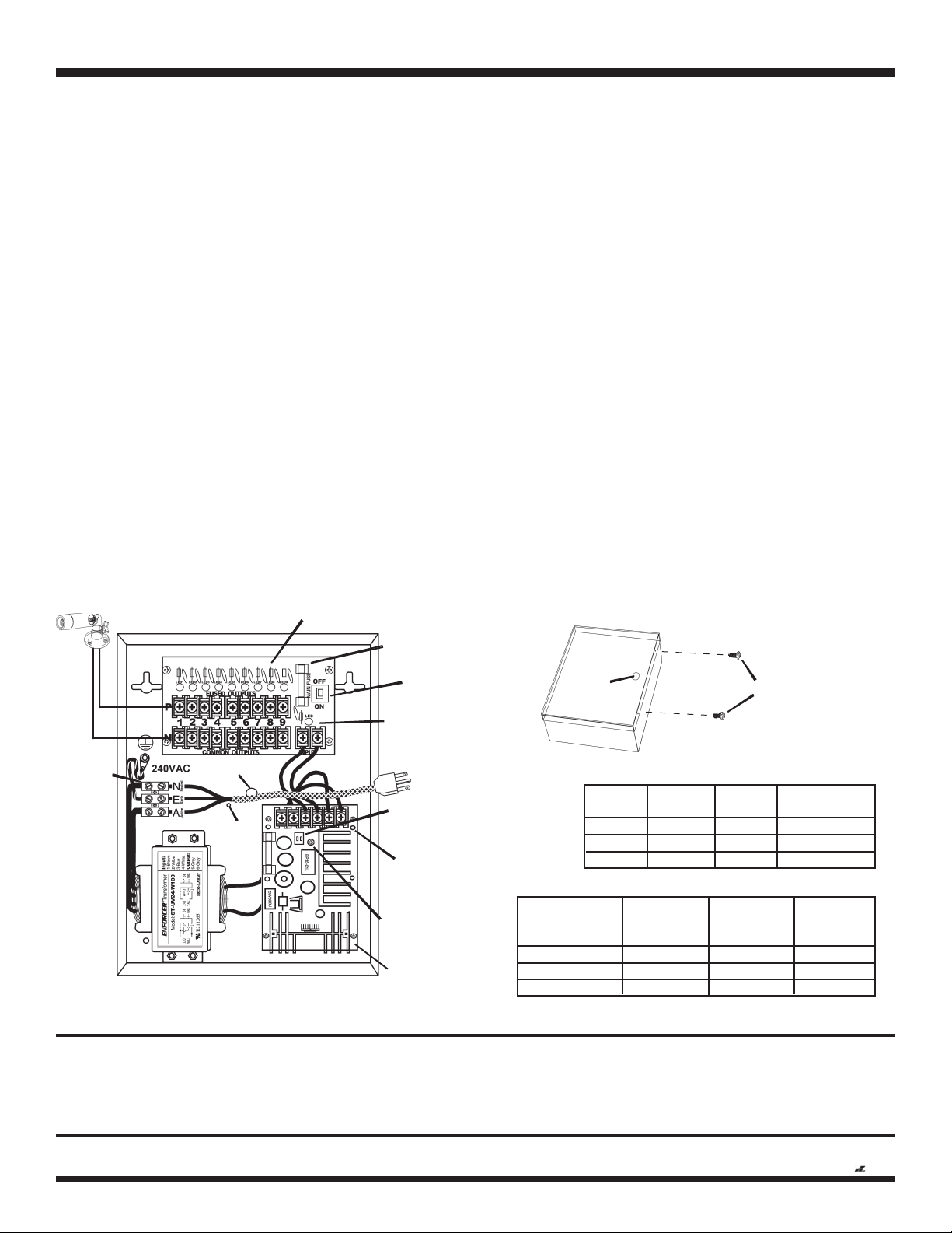
FIG. 2: Power Connections
EVP-224D4-P9QShown
Main
Switch
AC
Terminal
Block
Example: Output 1, 12VDC
ENFORCER
Main Fuse
Potentiometer
to Adjust DC
Voltage range
Dip Switch for
volt. selector
6/12/24VDC
173-001 PCB
ST-2406-5AQ PCB
Green LED
(Power Indicator)
Green LED
(Power Indicator)
Power cord
hole
For cable
clamp
use
FIG. 3: Securing the Enclosure:
Close the cover, then secure with included machine screws or optional cam lock.
Cam Lock
(optional)
Machine
Screws
(included)
EVP-224D2-P4Q
EVP-224D4-P9Q
EVP-224D6P16Q
Max. supply
current at
6VDC
2 Amp.
4 Amp.
6 Amp.
Max. supply
current at
12VDC
2 Amp.
4 Amp.
6 Amp.
Max. supply
current at
24VDC
1 Amp.
2 Amp.
3 Amp.
Table 2: Max. supply current chart
Model
Table 1: DC Voltage Output Dip Switch Settings
Voltage
6V
12V
24V
Dip SW1
ON
OFF
OFF
Dip SW2
OFF
OFF
ON
5.9~8.9
12.4~14.7
27.6~30
Voltage range
@ no load
WARRANTY: This SECO-LARM product is warranted against defects in material and workmanship while used in normal service for a period of one (1) year from the date of sale
to the original consumer customer. SECO-LARM’s obligation is limited to the repair or replacement of any defective part if the unit is returned, transportation prepaid, to SECO-LARM.
This Warranty is void if damage is caused by or attributed to acts of God, physical or electrical misuse or abuse, neglect, repair, or alteration, improper or abnormal usage, or faulty
installation, or if for any other reason SECO-LARM determines that such equipment is not operating properly as a result of causes other than defects in material and workmanship.
The sole obligation of SECO-LARM, and the purchaser’s exclusive remedy, shall be limited to replacement or repair only, at SECO-LARM’s option. In no event shall SECO-LARM be liable
for any special, collateral, incidental, or consequential personal or property damages of any kind to the purchaser or anyone else.
SECO-LARMSECO-LARM
SECO-LARMSECO-LARM
SECO-LARM®U.S.A., Inc.,U.S.A., Inc.,
U.S.A., Inc.,U.S.A., Inc.,
U.S.A., Inc., 16842 Millikan Avenue, Irvine, CA 92606
Tel: 800-662-0800 / 949-261-2999 Fax: 949-261-7326
Website: www.seco-larm.com
E-mail: sales
@
seco-larm.com
The SECO-LARM
®
policy is one of continual development and improvement. For that reason, SECO-LARM reserves the right to change specifications without notice. SECO-LARM is not responsible for misprints.
Copyright 2008 SECO-LARM U.S.A., Inc. All rights reserved.
MiEvpDc240_07C.pmd
Order Part #764-003-5%
PITSW1
5. Connect the power input wires of the CCTV cameras or accessories to the
PCB marked 173-001 (see Fig. 2). Observe correct polarity. The terminals
marked “P” are for positive wires, and “N” are for negative wires. Each
output consists of one “P” terminal and one “N” terminal.
Run wire pairs from the terminals through or along the wall to where the
CCTV cameras and/or accessories are mounted.
NOTE: Use minimum 18-gauge wires to minimize voltage drop.
NOTE:
Test each wire pair's voltage before connecting to cameras.
6. Turn the main switch ON. The green LED on the 173-001 PCB will light to
show that power is present. The red LEDs on the printed circuit board will
light to show each terminal pair is working correctly.
7. Test the voltage output at the end of each wire pair to see if there is any
significant voltage drop. The voltage output for all wire pairs should be
about the same unless a voltage drop occurred on a certain wire pair.
When running wires from the DC power supply, voltage drop can occur for
one of three reasons:
a. The wire is too thin. Use minimum 18-gauge wire.
b. The wire has run a long distance. If a wire pair is showing significant
voltage drop compared to the others, either shorten the length of the
voltage drop affected wire pair, or lengthen the other wire pairs to
have a similar voltage output reading on all wire pairs.
c. A large number of CCTV cameras and/or accessories connected to the
173-001 PCB is causing excessive power drain across all the outputs.
8.
Adjust the voltage output if needed - If the voltage output reading at the end
of the wire pair where it is connected to the camera or accessory
falls
below the minimum voltage required, use a screwdriver to carefully turn
the potentiometer located on the ST-2406 PCB to the right. (See Fig. 2 and
Table 1.) This will increase the total voltage output from the 173-001 PCB
to compensate for the voltage drop.
NOTE: Adjusting the potentiometer affects the voltage output of all the
wire pairs. Using a voltage output in excess of the specified voltage level
of a camera may cause damage.
9. After all adjustments, turn the main switch OFF.
10. Connect all the wire pairs to their respective CCTV cameras or
accessories.
Double-check the specified operating voltage of each before
connecting it to the device.
NOTE:
a. Connect a maximum of four devices (EVP-224D2-P4Q), nine devices
(EVP-224D4-P9Q), or 16 devices (EVP-224D6P16Q).
b. The CCTV cameras and accessories connected to the printed circuit
board must all operate on the same voltage (6VDC, 12VDC, or 24VDC).
c. The power supply is preset at 12VDC output. For 6VDC or 24VDC
operation, adjust the DIP switch (see Fig. 2 and Table 1).
d. Maximum total current connected to all terminals must not exceed the
power supply's total current capacity (2 Amp for EVP-224D2-P4Q,
4 Amp for EVP-224D4-P9Q, and 6 Amp for EVP-224D6P16Q).
11. Turn the main switch ON.
12. Close the steel door of the enclosure and secure it with either the provided
machine screws or an optional cam lock (see fig. 3).

This manual suits for next models

2

Other ENFORCER Power Supply manuals

ENFORCER PS-U0406-PULQ User manual

ENFORCER

ENFORCER PS-U0406-PULQ User manual

ENFORCER SECO-LARM SLI PC-U0405-PULQ User manual

ENFORCER

ENFORCER SECO-LARM SLI PC-U0405-PULQ User manual

ENFORCER PA-U0405-NULQ User manual

ENFORCER

ENFORCER PA-U0405-NULQ User manual

ENFORCER EB-P501-01Q User manual

ENFORCER

ENFORCER EB-P501-01Q User manual

ENFORCER ST-1206-1.5AQ User manual

ENFORCER

ENFORCER ST-1206-1.5AQ User manual

ENFORCER ENFORCER ST Series User manual

ENFORCER

ENFORCER ENFORCER ST Series User manual

ENFORCER SECO-LARM SLI ST-2406-3AEQ User manual

ENFORCER

ENFORCER SECO-LARM SLI ST-2406-3AEQ User manual

ENFORCER SB-P1012-26Q User manual

ENFORCER

ENFORCER SB-P1012-26Q User manual

ENFORCER EVP-1SA4P4UL User manual

ENFORCER

ENFORCER EVP-1SA4P4UL User manual

ENFORCER ENFORCER PH-A3224-PUQ User manual

ENFORCER

ENFORCER ENFORCER PH-A3224-PUQ User manual

ENFORCER PH-U1820-PULQ User manual

ENFORCER

ENFORCER PH-U1820-PULQ User manual

ENFORCER EVP-1SD2P4UL User manual

ENFORCER

ENFORCER EVP-1SD2P4UL User manual

ENFORCER ST-Series User manual

ENFORCER

ENFORCER ST-Series User manual

ENFORCER EAP-5D1Q User manual

ENFORCER

ENFORCER EAP-5D1Q User manual

ENFORCER PA-U0405-NULQ User manual

ENFORCER

ENFORCER PA-U0405-NULQ User manual

ENFORCER ST Series User manual

ENFORCER

ENFORCER ST Series User manual

ENFORCER PC-L1620-PQ User manual

ENFORCER

ENFORCER PC-L1620-PQ User manual

Popular Power Supply manuals by other brands

Videotec IRHPS instruction manual

Videotec

Videotec IRHPS instruction manual

Pulsar PSBEN 5012D manual

Pulsar

Pulsar PSBEN 5012D manual

Sureguard 160 manual

Sureguard

Sureguard 160 manual

MYERS MP Series operating manual

MYERS

MYERS MP Series operating manual

CDVI BS60 installation manual

CDVI

CDVI BS60 installation manual

M-system M5DYH2 instruction manual

M-system

M-system M5DYH2 instruction manual

RPC 50P00P user manual

RPC

RPC 50P00P user manual

Rockwell Automation 1606-XLERED instruction manual

Rockwell Automation

Rockwell Automation 1606-XLERED instruction manual

HP E3630A operating manual

HP

HP E3630A operating manual

Pulsar PSD15040 manual

Pulsar

Pulsar PSD15040 manual

Bosch LTC 5404/60 installation instructions

Bosch

Bosch LTC 5404/60 installation instructions

Keithley SourceMeter 2470 user manual

Keithley

Keithley SourceMeter 2470 user manual

RCF FORUM FPS9600 user manual

RCF

RCF FORUM FPS9600 user manual

Pulsar AWZ 820-PSU-S-12V/L-3.5A/9/FTA-TR-MC quick start guide

Pulsar

Pulsar AWZ 820-PSU-S-12V/L-3.5A/9/FTA-TR-MC quick start guide

Akyga AK-ND-61 user manual

Akyga

Akyga AK-ND-61 user manual

PS Audio PerfectWave Power Plant 5 Owner reference guide

PS Audio

PS Audio PerfectWave Power Plant 5 Owner reference guide

OCZ OCZGXS850 manual

OCZ

OCZ OCZGXS850 manual

Hameg HM7042-5 manual

Hameg

Hameg HM7042-5 manual

manuals.online logo
manuals.online logoBrands
  • About & Mission
  • Contact us
  • Privacy Policy
  • Terms and Conditions

Copyright 2025 Manuals.Online. All Rights Reserved.