manuals.online logo
Brands
  1. Home
  2. •
  3. Brands
  4. •
  5. ENFORCER
  6. •
  7. Power Supply
  8. •
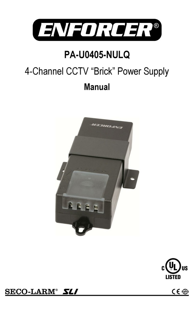
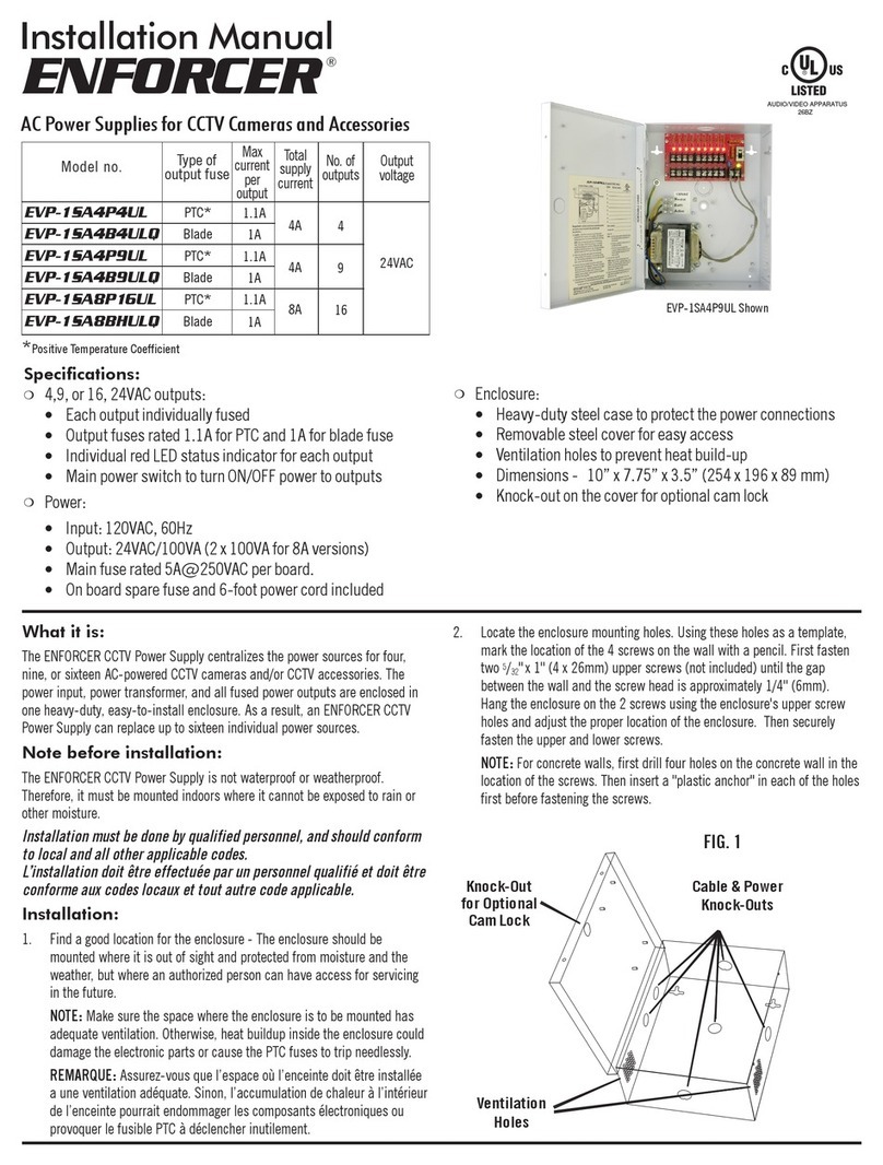
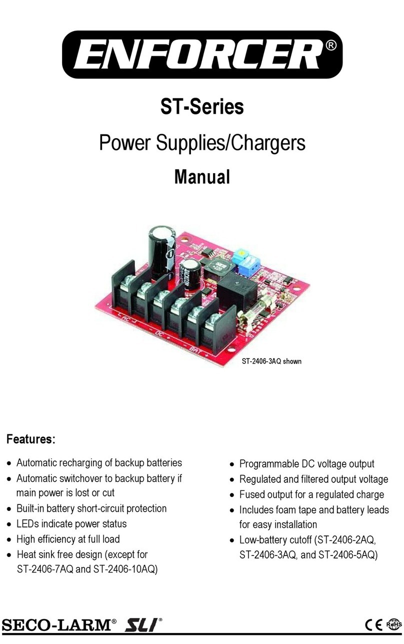
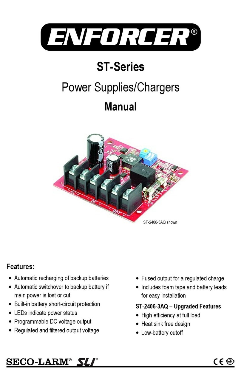
  9. ENFORCER PS-U0406-PULQ User manual

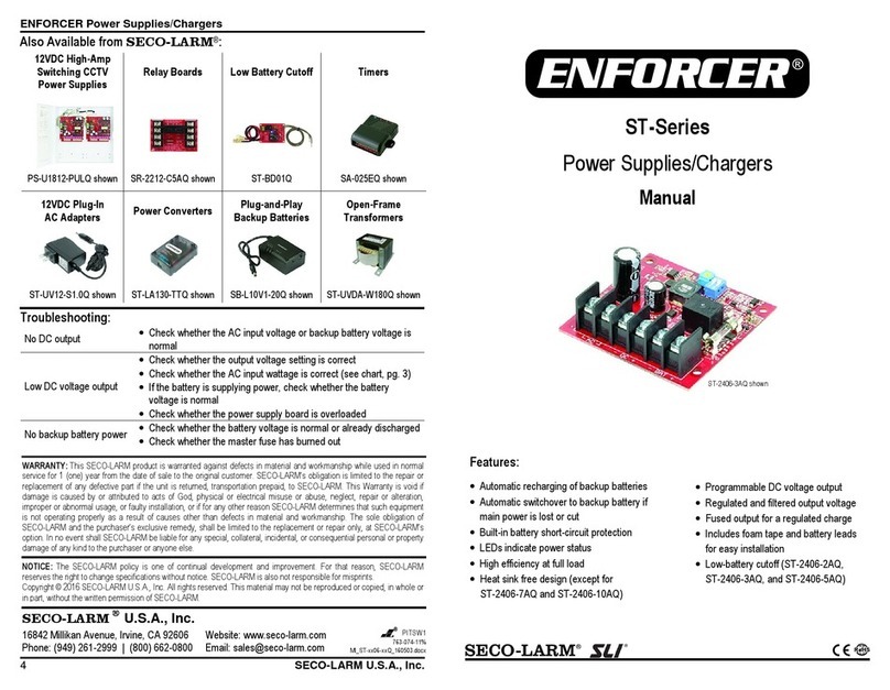
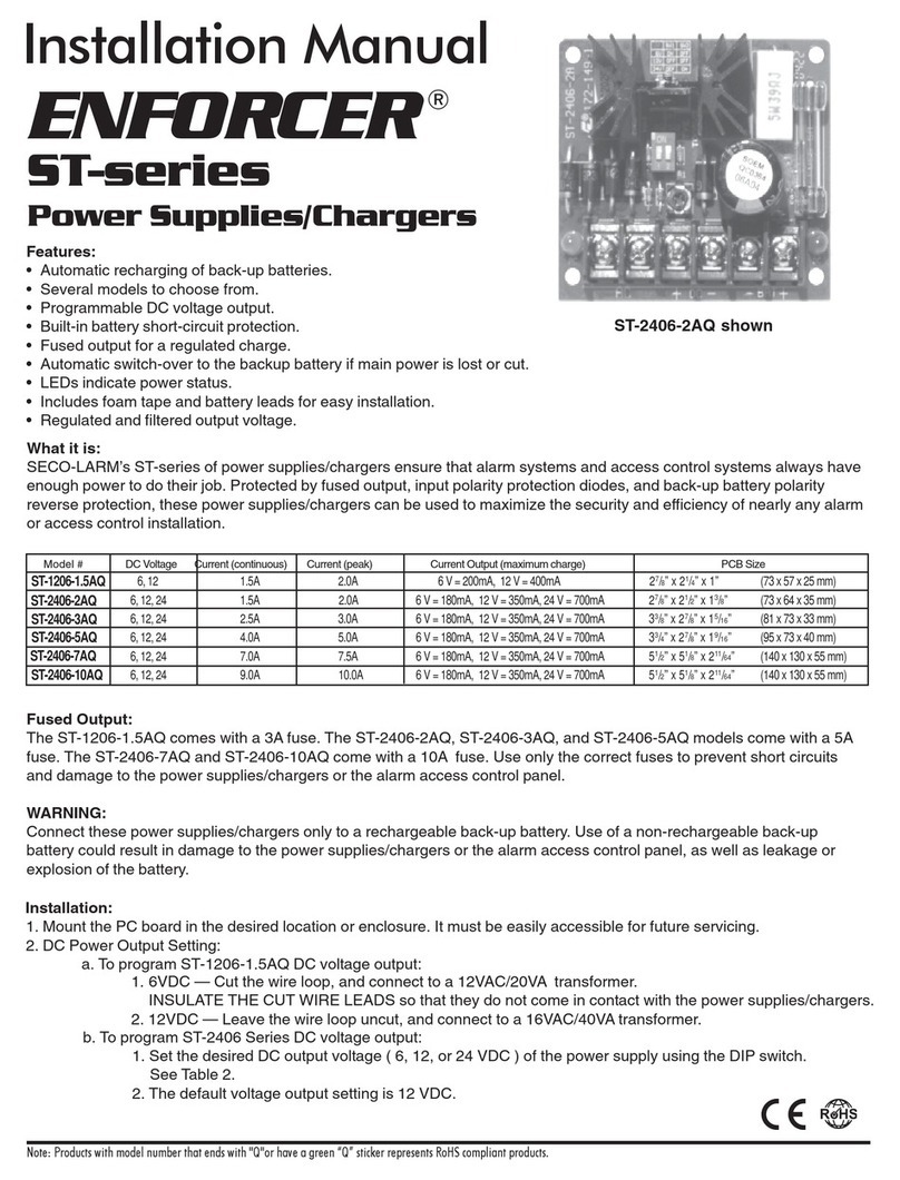
ENFORCER PS-U0406-PULQ User manual

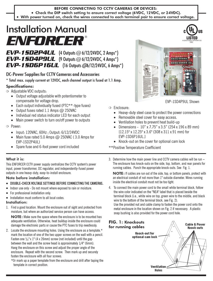
ENFORCER DC Switching CCTV Power Supply
4 SECO-LARM U.S.A., Inc
7. If voltage drop is large, adjust the output
voltage trimpot as shown in Figure 7.
NOTE / REMARQUE: The output voltage
trimpot changes voltage for all outputs.
Test all outputs to ensure voltage does not
exceed device specifications. Le
potentiomètre de tension des sorties
change la tension de toutes les sorties.
érifiez toutes les sorties pour assurer que
la tension ne dépasse pas les
spécifications de l’appareil.
Also Available from SECO-LARM:
CCTV
Power Su lies
PS-D1610-BUQ
CCTV Cameras
E -2726-NFGQ
DVRs
DR-1 Series
Baluns
E T-PB1Q
DC Connectors
CA-161T / CA-151R
Voltage Converters & Boosters
ST-HB105-TTQ
WARRANTY: This SECO-LARM product is warranted against defects in material and workmanship
while used in normal service for a period of one (1) year from the date of sale to the original consumer
customer. SECO-LARM’s obligation is limited to the repair or replacement of any defective part if the
unit is returned, transportation prepaid, to SECO-LARM. This Warranty is void if damage is caused by
or attributed to acts of God, physical or electrical misuse or abuse, neglect, repair, or alteration,
improper or abnormal usage, or faulty installation, or if for any other reason SECO-LARM determines
that such equipment is not operating properly as a result of causes other than defects in material and
workmanship. The sole obligation of SECO-LARM, and the purchaser’s exclusive remedy, shall be
limited to replacement or repair only, at SECO-LARM’s option. In no event shall SECO-LARM be
liable for any special, collateral, incidental, or consequential personal or property damages of any kind
to the purchaser or anyone else.
NOTICE: The information and specifications printed in this manual are current at the time of
publication. However, the SECO-LARM policy is one of continual development and improvement. For
this reason, SECO-LARM reserves the right to change specifications without notice. SECO-LARM is
also not responsible for misprints or typographical errors.
Copyright © 2014 SECO-LARM U.S.A., Inc. All rights reserved. This material may not be reproduced
or copied, in whole or in part, without the written permission of SECO-LARM.
SECO-LARM
®
U.S.A., Inc.
16842 Millikan Avenue, Irvine, CA 92606 Website: www.seco-larm.com
Tel: 800-662-0800 / 949-261-2999 Fax: 949-261-7326 E-mail: sales@seco-larm.com
MiPS
-
Uxxxx
-
PULQ
_1
312
.docx
Order part # 764-507-3%
PI
T
SW1
Figure 7 – Adjusting output voltage
12VDC Switching CCTV Power Su ly
Manual
Model
Number
Number
of
Out uts
Total
Su ly
Current
Max.
Current
er Out ut
PS
-
U
04
06
-
PU
L
Q
1
PS-U0406-PTQ 4 6A 2.5A
2
PS
-
U
09
06
-
PU
L
Q
1
PS-U0906-PTQ 9 6A 2.5A
2
PS
-
U
1806
-
PU
L
Q
1
PS-U1806-PTQ 18 6A 2.5A
2
PS
-
U
1812
-
PU
L
Q
1
PS-U1812-PTQ 18 12A 2.5A
2
PS
-
U36
12
-
PULQ
1
PS-U3612-PTQ 36 12A 2.5A
2
1
UL approved models and includes power cable with NEMA 5—15 plug connector.
2
Positive Temperature Coefficient (PTC) output fuse rating
PS
-
U0906
-
PU
L
Q
shown
Note: Products with model numbers that end with “Q” or that have a round
green “Q” sticker are RoHS compliant.
Audio/ ideo Apparatus
26BZ
ENFORCER DC Switching CCTV Power Supply
2 SECO-LARM U.S.A., Inc
Features:
•
Universal
100
~2
4
0 AC input.
•New lightweight, cost-effective design.
•Improved efficiency.
•Adjustable output to reduce voltage drop.
•
Outputs protected with 2.5A PTC
1
fuses.
•Individual output status LEDs.
•Heavy-duty steel case with removable cover.
•Built-in short circuit and overheat protection.
Parts List:
S ecifications:
PS-U0406-PULQ
PS-U0406-PTQ4
PS-U0906-PULQ
PS-U0906-PTQ4
PS-U1806-PULQ
PS-U1806-PTQ4
PS-U1812-PULQ
PS-U1812-PTQ4
PS-U3612-PULQ
PS-U3612-PTQ4
Outputs
4
9
18
18
36
Total supply current
6A
12A
Max
.
current
/
output
2.5A
Output fuse
PTC
1
Output voltage
12.6~13.5 DC
Input fuse
Micro fuse 3.
1
5A@250 AC
Input voltage
100
~2
4
0 AC (
47
~6
3
Hz)
Dimensions 10”x7
3
/
4
”x3
5
/
8
” (254x196x92 mm)
12
1
/
8
”
x12
1
/
4
”
x3
5
/
8
”
(308x311x92 mm)
Weight
(Approx.)
4
-
lb
7
-
oz
(2.
01
kg)
7
-
lb 1
0
-
oz (
3
.
4
5kg)
Overview:
Installation Notes / Notes d’installation:
•ALWAYS TEST OUTPUT VOLTAGE BEFORE CONNECTING DEVICES. TOUJOURS,
VÉRIFIEZ LA TENSION DE SORTIE AVANT DE CONNECTER L’APPAREIL.
•Indoor use only. Do not mount the unit where it may be exposed to weather or high humidity.
Utilisé à l’intérieur seulement. N’installez pas l’appareil là où il peut être exposé aux
intempéries ou à une humidité élevée.
•For professional installation only. Pour installation professionnelle seulement.
•Installation must conform to all local laws and building codes. L’installation doit se conformer à
toutes les lois locales et code du bâtiment.
Installation:
1. Find a suitable location to install the power supply. The power supply should be installed out of
sight, and in a place protected from weather and high humidity. The power supply must have
adequate ventilation. Insufficient ventilation may cause overheating and damage could result.
1Positive Temperature Coefficient. 2PULQ models only. 34 pcs for 18-output models, 8 pcs for 36-output models.
4PULQ and PTQ models are identical except PULQ models are UL approved and include a NEMA 5—15 plug power cable.
PCB from PS-U0906-PULQ shown
Main Power Switch
Power Output Terminals
Output
Indicator
LEDs
Power Input
Terminal
Output oltage
Trimpot
Power supply
............
x1
Plastic bushing .......... x1
Enclosure screws
......
x
2
Cable clamp
..............
x1
Cable clamp nut ........ x2
Manual
......................
x
1
Power cable
2
.............
x1
Cable tie3 ................... x2
ENFORCER DC Switching CCTV Power Supply
SECO-LARM U.S.A., Inc 3
2. Remove one or more of the power
cable knock-outs depending on how
connections will be made. Knock-outs
are shown in Figure 1 to the right. If
desired, use an optional bushing,
grommet or another sleeve to protect
wires passing through the hole(s).
3. If desired, a cam lock (not included) can
be installed in the knock-out located in
the middle right of the cover of the unit.
4. Screw the power supply on to the wall
or other mounting surface using four
5
/
32
”x1” (4x26 mm) screws and plastic
anchors (not included). First, screw in
the top two screws and hang the power
supply. Then screw in the bottom two
screws to fully secure the unit in place.
5. PS-Uxx06 series: Connect the main
power cable
1
to the PCB’s power input
terminal as shown in Figure 3. Connect
the green ground wire to the enclosure
ground pin using the included nut as
shown in Figure 4.
PS-Uxx12 series: Connect the main
power cable
1
to the empty terminals of
the white terminal block as shown in the
connection legend inside the power
supply housing and the Figure 5 diagram.
IMPORTANT: The power cable
1
must be
secured with the included white plastic
cable clamp and nut to the housing. If
using the rear power cable port, install
the included plastic bushing on the
cable port to protect the cable from
abrasion.
Le câble1 d’alimentation doit être assuré
au boîtier avec l’écrou et le collier de
serrage en plastique blanc inclus. Si
vous utilisez le port d’alimentation
arrière, installez la traversée de
plastique incluse sur le port de câble
pour protéger le câble contre abrasion.
6. Connect cameras and other devices to
the power outputs, while observing
correct polarity as shown in Figure 6. To
minimize voltage drop, use 18-gauge or
larger wire.
WARNING / AVERTISSEMENT: Always
test output voltage before connecting
devices to the power supply. Toujours,
vérifiez la tension de sortie avant de
connecter l’appareil à l’alimentation.
(Continued on page 4)
1
Power cable included with PULQ models only.
Figure 1 – Knock-outs
Cam Lock Knock-out
Power Cable
Knock-outs
entilation Holes
Figure 2 – Mounting
Upper Mounting Holes
Lower Mounting Holes
Figure 5 – Main po er cable
(PS-Uxx12 series
)
A
Black wire
(Active)
E
Green wire
(Earth)
N
White wire (Neutral)
Factory
re-wired
connections
Figure 6 – Connecting po er outputs
Negative ( )
Positive ( )
Figure 3 – Main po er cable
(PS-Uxx06 series)
Black wire
(Active)
A
White wire (Neutral)
N
Figure 4 – Connecting po er cable
(PS-Uxx06 series)
Power input terminal
Positive (+) wire (black)
Negative (-) wire (white)
Cable clamp
Ground wire (green)
Ground
pin
Plastic snap bushing

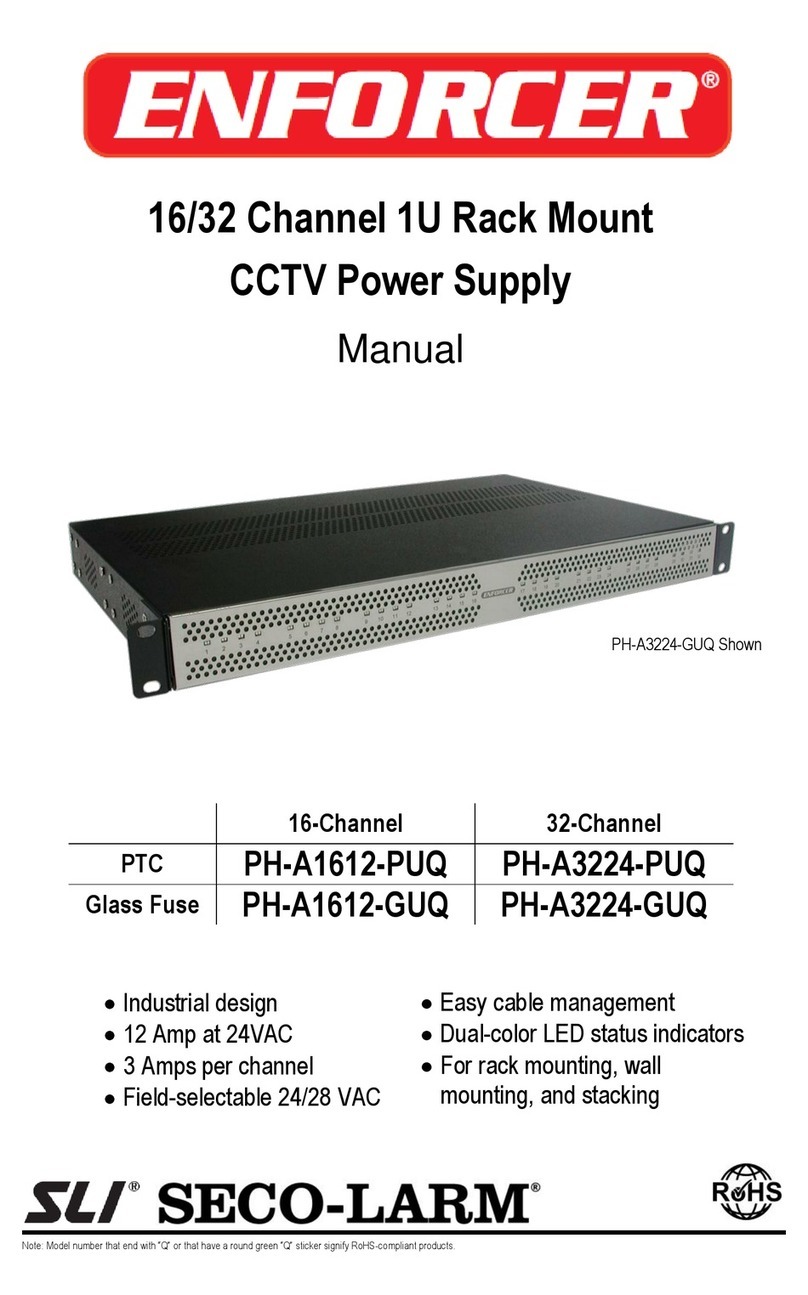
This manual suits for next models

9

Other ENFORCER Power Supply manuals

ENFORCER PA-U0405-NULQ User manual

ENFORCER

ENFORCER PA-U0405-NULQ User manual

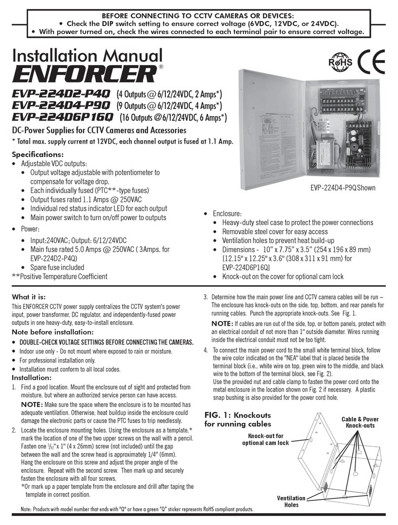
ENFORCER EVP-224D2-P4Q User manual

ENFORCER

ENFORCER EVP-224D2-P4Q User manual

ENFORCER SB-P1012-26Q User manual

ENFORCER

ENFORCER SB-P1012-26Q User manual

ENFORCER ENFORCER ST Series User manual

ENFORCER

ENFORCER ENFORCER ST Series User manual

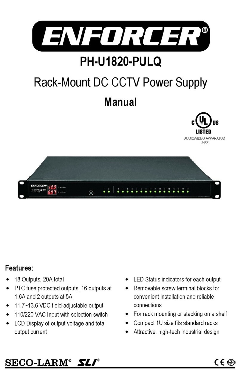
ENFORCER PH-U1820-PULQ User manual

ENFORCER

ENFORCER PH-U1820-PULQ User manual

ENFORCER ST Series User manual

ENFORCER

ENFORCER ST Series User manual

ENFORCER EB-P501-01Q User manual

ENFORCER

ENFORCER EB-P501-01Q User manual

ENFORCER EVP-1SD2P4UL User manual

ENFORCER

ENFORCER EVP-1SD2P4UL User manual

ENFORCER EVP-1SA4P4UL User manual

ENFORCER

ENFORCER EVP-1SA4P4UL User manual

ENFORCER ENFORCER PH-A3224-PUQ User manual

ENFORCER

ENFORCER ENFORCER PH-A3224-PUQ User manual

ENFORCER PA-U0405-NULQ User manual

ENFORCER

ENFORCER PA-U0405-NULQ User manual

ENFORCER PC-L1620-PQ User manual

ENFORCER

ENFORCER PC-L1620-PQ User manual

ENFORCER SECO-LARM SLI PC-U0405-PULQ User manual

ENFORCER

ENFORCER SECO-LARM SLI PC-U0405-PULQ User manual

ENFORCER EAP-5D1Q User manual

ENFORCER

ENFORCER EAP-5D1Q User manual

ENFORCER SECO-LARM SLI ST-2406-3AEQ User manual

ENFORCER

ENFORCER SECO-LARM SLI ST-2406-3AEQ User manual

ENFORCER ST-Series User manual

ENFORCER

ENFORCER ST-Series User manual

ENFORCER ST-1206-1.5AQ User manual

ENFORCER

ENFORCER ST-1206-1.5AQ User manual

Popular Power Supply manuals by other brands

ScienceTech 500-75ST user manual

ScienceTech

ScienceTech 500-75ST user manual

TTI TSX Series instruction manual

TTI

TTI TSX Series instruction manual

Keysight U8001A User's and service guide

Keysight

Keysight U8001A User's and service guide

Amrel PPS-1326 manual

Amrel

Amrel PPS-1326 manual

Monster Power Reference PowerCenter HTS2600 owner's manual

Monster Power

Monster Power Reference PowerCenter HTS2600 owner's manual

alfatronix PR65R Operating & assembly instructions

alfatronix

alfatronix PR65R Operating & assembly instructions

Broadata Communications Link Bridge LBC-24PI user manual

Broadata Communications

Broadata Communications Link Bridge LBC-24PI user manual

GW Instek GPP-3650 user manual

GW Instek

GW Instek GPP-3650 user manual

NI PXIe-1075 user guide

NI

NI PXIe-1075 user guide

Musical Fidelity TRIPLE-X170 Instructions for use

Musical Fidelity

Musical Fidelity TRIPLE-X170 Instructions for use

Fuji Electric FA5502P Application note

Fuji Electric

Fuji Electric FA5502P Application note

Sorensen QSA Series instruction manual

Sorensen

Sorensen QSA Series instruction manual

Puls DIMENSION CS5.243 manual

Puls

Puls DIMENSION CS5.243 manual

SFC Energy EFOY Pro Series quick start guide

SFC Energy

SFC Energy EFOY Pro Series quick start guide

Peak PKC0AN owner's manual

Peak

Peak PKC0AN owner's manual

Simu 9014738 instructions

Simu

Simu 9014738 instructions

McIntosh D-101 brochure

McIntosh

McIntosh D-101 brochure

Puls Dimension QS3 Series instruction manual

Puls

Puls Dimension QS3 Series instruction manual

manuals.online logo
manuals.online logoBrands
  • About & Mission
  • Contact us
  • Privacy Policy
  • Terms and Conditions

Copyright 2025 Manuals.Online. All Rights Reserved.