4
Fig. 4.1. Timing Relationships for Input and Output
Pulses.
pulses, but only the positive signal lobe will be
analyzed. When coaxial cables longer than about 4
ft are connected to the Model 550A input, cable
terminationmaybenecessarytopreventreflections
from corrupting the signal to be analyzed. In this
situation, terminate the cable in its characteristic
impedanceat the Model 550A input connector. The
input operating range is from +20 mV to +10 V, and
is compatible with NIMlinearand biased amplifiers.
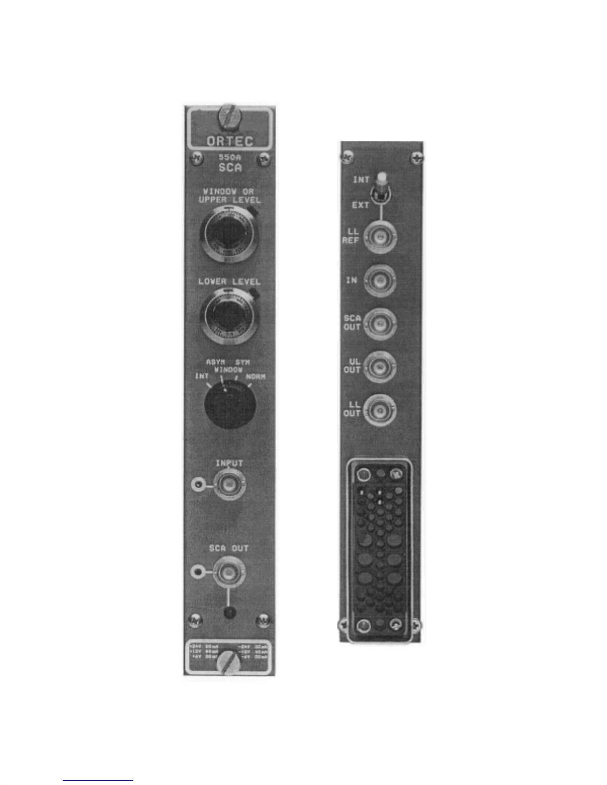
3.3. OUTPUT CONNECTIONS
The logic output pulses generated by the Model
550A are available from both front- and rear-panel
BNC connectors for convenience when installing
the Model 550A in a system. When the Model 550A
is used in the NORMAL or WINDOW modes, a
pulse from the SCA output means that the input
signal amplitude is large enough to trigger the
lower-level discriminator but not large enough to
trigger the upper-level or window discriminator.
When the Model 550A is in the INTEGRAL mode,
an SCA output pulse means that the input signal
amplitude is large enough to trigger the lower-level
discriminator.
Separate logic outputs are available on the rear
panel to indicate the time at which the leading edge
of theinput signal triggeredthelevel discriminators.
These outputs can be used to monitor the
discriminator levels during adjustment, counted in
external scalers, to provide subgroup routing in a
multichannel analyzer, or for other applications as
desired.
Each logic output is a NIM-standard slow-positive
pulse that is compatible with all ORTEC
instruments. The impedance of each output is
sufficiently low to drive as many as ten 1000
S
inputs in parallel.
3.4. LOWER LEVEL REFERENCE INPUT
If the toggle switch on the rear panel of the Model
550A is set to EXT, the front-panel Lower Level
control is disabled and the reference level for the
lower-level discriminator must be supplied through
the adjacent LL REF connector. An input of 0 to -10
V through this connector corresponds directly to a
range of 0 to +10 V for the lower-level discriminator
threshold. It a signal is connected to the LL REF
connector when the INT/EXT switch is in the INT
position, the signal through the connector is
ignored.
4. OPERATING INSTRUCTIONS
After the Model 550A has been installed in a
system according to the installation information in
Section 3, the operating mode can be selected and
the discriminator thresholds can be adjusted as
required for each application.
Figure 4.1 illustrates the timing relationships that
will be effective in the Model 550A for each of two
possible input pulse conditions. One is a pulse that
exceeds the lower-level threshold without
exceeding the upper level, and the other is a pulse
that exceeds both thresholds. If the front-panel
rotary switch selectsthe INTEGRAL mode, an SCA
output pulse is generated when the trailing edge of
each input pulse crosses the lower-level threshold.
If the NORMAL, SYMMETRIC WINDOW, or