S1D13U11 Display Controller
S5U13U11 Evaluation Board User Manual (Rev. 1.1) EPSON 7
Chapter 3 Installation and Configuration
The S5U13U11 evaluation board incorporates jumpers and 0 ohm resistors which allow it to be used in a variety of
different configurations.
3.1 Configuration Jumpers
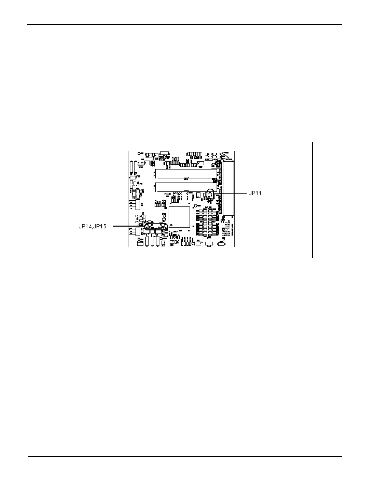
The S5U13U11 has 15 jumpers which configure various board settings. The jumper positions for each function are
shown below. JP5, JP6, JP7, JP8, JP9, JP10, JP11, JP14 and JP15 are solder bridges to reduce power noise. To
change the jumper position remove the solder.
JP1 - Current Measurement of the S5U13U11 Evaluation Board
JP1 can be used to measure the current consumption of the S5U13U11 power supply.
When the jumper is at position 1-2, normal operation is selected.
When no jumper is installed, the current consumption for power supply can be measured by connecting an ammeter
between pins 1 and 2 of the jumper.
Jumper Function Position 1-2 Position 2-3 No Jumper
JP1 Board current measurement Normal —Current measurement
JP2 Board power supply VBUS 5V input External DC5V —
JP3 VBUS input signal VBUS 5V input External DC5V —
JP4 Power-on reset source VBUS 5V input External DC5V —
JP5 COREVDD current measurement Normal —Current measurement
JP6 PLLVDD current measurement Normal —Current measurement
JP7 PIOVDD current measurement Normal —Current measurement
JP8 USBVDD current measurement Normal —Current measurement
JP9 MIOVDD current measurement Normal —Current measurement
JP10 Touch screen power 5V 3.3V (Position 1-3) —
JP11 External 3.3V current measurement Normal —Current measurement
JP12 LED Backlight 12V power control ON —OFF
JP13 Ortustech panel control ON/OFF control Always ON —
JP14 3.3V regulator current measurement Normal —Current measurement
JP15 1.8V regulator current measurement Normal —Current measurement
= Default setting