ERGODYNE 3197 User manual

INTRODUCTION
Before first use of the Ergodyne Full Body Harness, this
manual must be read and understood in its entirety by the
user of the Ergodyne Full Body Harness and consumed
as part of a fall protection training program as required
by the Occupational Health and Safety Administration
(OSHA) or any state/local regulatory agencies. All product
labels must also be read and understood. This instruction
manual must be retained for reference by the user. All
product labels must remain intact and not be altered
during use. Only the equipment manufacturer, or persons
or entities authorized in writing by the manufacturer, may
make repairs to the equipment.
WARNING! SAVE THESE INSTRUCTIONS. THE
ERGODYNE FULL BODY HARNESS MUST NOT BE
USED BY ANYONE WHO HAS NOT READ,
UNDERSTOOD AND FOLLOWED ALL INSTRUCTIONS
AND INSPECTION PROCEDURES CONTAINED IN THIS
INSTRUCTION MANUAL. FAILURE TO OBSERVE
THESE WARNINGS, INSTRUCTIONS AND INSPECTION
PROCEDURES COULD LEAD TO SERIOUS INJURY OR
DEATH. TRAINING AND INSTRUCTION REVIEW
SHOULD BE REPEATED AT REGULAR INTERVALS
BY THE USER AND THEIR EMPLOYER.
THE A-B-C RULE
To be complete, a personal fall protection system must
include at least one piece of equipment from each of
the A-B-C components (for an example, see fig. 1A and
1B). Some personal fall protections systems may include
more than one piece of equipment in each component.
Choosing the proper equipment depends on the jobsite
and the application. A Competent Person, as defined by
OSHA, must make these equipment decisions.
A personal fall protection system is more than just
a combination of equipment. To function properly,
the system must be custom designed for the specific
application, environment and worksite requirements.
Follow the A-B-C Rule when assembling personal fall
protection system. The system must contain all the
following components: (A) anchorage, (B) body wear
and (C) connecting device.
Anchorage (A) OSHA defines anchorage as “a secure
point of attachment for lifelines, lanyards or deceleration
devices”. Choosing the proper anchorage is determined
by the type of fall protection needed (fall arrest, or fall
arrest combined with positioning, suspension and/or
retrieval functions). The anchorage must be identified and
evaluated by a Competent Person, as defined by OSHA, at
the jobsite before the appropriate personal fall protection
equipment can be selected. Typical anchorages could be
an I-beam or other structural members.
Body Wear (B) The second component of a personal
fall protection system is body wear such as a full body
harness. To select the right harness for the jobsite
requirements, a Competent Person, as defined by OSHA,
must determine the type of fall protection needed (such
as fall arrest, or fall arrest combined with positioning,
suspension and/or retrieval capabilities). Whenever there
is a risk of a fall, fall arrest protection must be used.
OSHA prohibits the use of a body belt for fall arrest.
ERGODYNE®3197
FULL BODY HARNESS
WWW.ERGODYNE.COM // 800 225 8238
USER INFORMATION
DATE OF FIRST USE
SERIAL #
TRAINER
USER
FALL ARREST - FIG. 1A TRAVEL RESTRAINT - FIG. 1B
Rev. 07/21 A
1390528
(A) ANCHORAGE
(A) ANCHORAGE
(B) BODY WEAR
(B) BODY WEAR
(C) CONNECTOR
(C) CONNECTOR

2
Connecting Device (C) The third component of
personal fall protection system is the connecting device.
Examples include lanyards, rope grabs and deceleration
devices. As with anchorages and body wear, choosing
a proper connecting device is dictated by other system
components and jobsite requirements. Only use
connecting devices equipped with locking snap hooks.
OSHA prohibits the use of connecting devices without
locking snap hooks in any fall protection system.
CLASSIFICATION OF WORKERS
It is important to be familiar with OSHA’s 29 CFR 1926.32
definitions for workers. These definitions are applied
below to workers who work near fall hazards, may
be exposed to fall hazards or have responsibility for
determining the appropriate elements of an employer’s
fall safety program. These definitions are referenced
throughout this instruction manual.
Qualified Person: “Qualified” means one who, by
possession of a recognized degree, certificate or
professional standing, or who by extensive knowledge,
training and experience, has successfully demonstrated
their ability to solve or resolve problems relating to the
subject matter, the work or the project. In this case,
a person considered meeting the criteria above and
considered proficient in planning and reviewing the
conformity of fall protection and rescue systems.
Competent Person: “Competent person” means one who
is capable of identifying existing and predictable hazards
in the surroundings or working conditions which are
unsanitary, hazardous or dangerous to employees, and
who has authorization to take prompt corrective measures
to eliminate them. In this case, a person assigned by the
employer to oversee and be responsible for all aspects
of the employer’s fall safety program. This person’s
responsibility includes but is not limited to the fall safety
program’s regulation, management and application. This
person is proficient in identifying existing and predictable
fall hazards and has the authority to stop work in order
to eliminate hazards.
Authorized Person: “Authorized person” means a person
approved or assigned by the employer to perform a
specific type of duty or duties or to be at a specific
location or locations at the jobsite. In this case, a person
authorized to work near or be exposed to potential or
existing fall hazards.
APPLICABLE SAFETY STANDARDS
AND REGULATIONS
When used in accordance with these instructions, this
product meets or exceeds all applicable ANSI Z359.11-
2014 standards and regulations for fall protection. It
is important to note that applicable standards and
regulations depend on the type of work being done
and additional state and local standards and regulations
may apply. To ensure this equipment is appropriate
for a specific application, consult a Qualified Person as
well as relevant state and local regulatory agencies for
more information on personal fall arrest systems and
associated components.
WARNING! IT IS THE EMPLOYER’S RESPONSIBILITY
TO ENSURE THAT A QUALIFIED OR COMPETENT
PERSON SUPERVISES THE JOBSITE TO ENSURE
ALL EQUIPMENT, PRACTICES AND ACTIVITY
COMPLIES WITH ALL APPLICABLE SAFETY
STANDARDS AND REGULATIONS.
PROPER METHOD OF USE OF EQUIPMENT
OSHA defines multiple types of personal fall protection
systems, but the Ergodyne Full Body Harness is
appropriate for use in very specific applications.
The precise definitions of these applications from
OSHA CFR 1910.140(b)* are listed below:
Personal Fall Arrest: Personal fall
arrest system means a system used
to arrest an employee in a fall from a
walking-working surface. It consists
of a body harness, anchorage and
connector. The means of connection
may include a lanyard, deceleration
device, lifeline or a suitable
combination of these. The Ergodyne
Full Body Harness is designed for
use in personal fall arrest
applications.
Travel Restraint: Travel restraint
system means a combination of an
anchorage, anchorage connector,
lanyard (or other means of
connection) and body support that
an employer uses to eliminate the
possibility of an employee going
over the edge of a walking-working
surface. The Ergodyne Full Body
Harness is designed for use in travel
restraint applications.
WARNING! THE ERGODYNE FULL BODY HARNESS
MAY BE USED ONLY IN PERSONAL FALL ARREST
AND TRAVEL RESTRAINT SYSTEMS. USE OF
THE ERGODYNE FULL BODY HARNESS IN ANY
OTHER TYPE OF FALL PROTECTION SYSTEMS
COULD RESULT IN SERIOUS INJURY OR DEATH.
A QUALIFIED OR COMPETENT PERSON MUST MAKE
A DETERMINATION REGARDING COMPATIBILITY OF
THE ERGODYNE FULL BODY HARNESS WITH THE
PARTICULAR APPLICATION.
WARNING! WHEN USING THE ERGODYNE FULL
BODY HARNESS IN ACTIVE TRAVEL RESTRAINT
APPLICATIONS, IT IS CRITICAL TO USE A FALL
RESTRAINT LANYARD THAT LIMITS TRAVEL IN
SUCH A MANNER THAT THE USER IS NOT EXPOSED
TO A FALL HAZARD. USING THE INCORRECT LENGTH
LANYARD COULD RESULT IN SERIOUS INJURY OR
DEATH. A TRAVEL RESTRAINT SYSTEM MUST ALLOW
A PERSON TO APPROACH THE EDGE BUT ELIMINATE
THE POSSIBILITY OF FALLING.
LIMITATIONS OF EQUIPMENT
GENERAL LIMITATIONS
Fall protection systems must be designed by a Qualified
Person and must be installed and used by an Authorized
Person under the supervision of a Competent Person.
The Ergodyne Full Body Harness must not be used for
any application other than that for which it has been
designed and certified.
Using improper combinations of components, sub-
systems or both may aect or interfere with the safe
function of the components, sub-systems or both. To
minimize the potential for accidental disengagement
and help ensure safe function, a Competent Person must
ensure compatibility of all components of the personal
fall protection system.

3
Do not use the Ergodyne Full Body Harness near sharp
edges and abrasive surfaces.
Do not use the Ergodyne Full Body Harness around
moving machinery or electrical hazards.
Do not expose the Ergodyne Full Body Harness or PPE
to UV light to avoid UV degradation.
The Ergodyne Full Body Harness must be protected from
slag, hot sparks, open flames or other heat sources.
Do not expose the Ergodyne Full Body Harness to
chemicals or other substances which may have a harmful
eect on the materials from which it is made. If unsure of
chemical or substance compatibility with the Ergodyne
Full Body Harness, please contact Ergodyne for further
instruction.
Proper precautions should always be taken to remove any
obstructions, debris or other recognized hazards from the
work area that could cause injuries or interfere with the
operation of the personal fall protection system.
The Authorized Person shall have a rescue plan and the
means at hand to implement it when using this equipment.
The Ergodyne Full Body Harness must be inspected prior
to each use according to the instructions contained in
this instruction manual. All equipment should also be
inspected by a Qualified Person on a regular basis.
The Ergodyne Full Body Harness must not be altered
in any way. Alterations could lead to serious injury or
death. If any alterations are made to the harness, it must
be immediately removed from service, destroyed and
discarded to prevent future use.
Consult a doctor if there is any reason to doubt a user’s
ability to withstand and safely absorb fall arrest forces.
Age, fitness and health conditions can seriously aect the
worker should a fall occur. Pregnant women and minors
should not use this equipment.
If inspection of the Ergodyne Full Body Harness reveals
any damage, deformities, unusual wear or deterioration,
it must immediately be retired from service.
WARNING! IN BOTH PERSONAL FALL ARREST
AND TRAVEL RESTRAINT APPLICATIONS, THE
WEIGHT CAPACITY RANGE OF THE ERGODYNE
FULL BODY HARNESS IS 130-310 LBS—INCLUDING
ALL CLOTHING, TOOLS AND EQUIPMENT. USE OF
THE ERGODYNE FULL BODY HARNESS OUTSIDE
THIS WEIGHT CAPACITY RANGE COULD RESULT
IN SERIOUS INJURY OR DEATH.
WARNING! ANY ERGODYNE FULL BODY HARNESS
SUBJECTED TO A FALL MUST BE IMMEDIATELY
REMOVED FROM SERVICE AND DESTROYED TO
PREVENT FUTURE USE.
FALL CLEARANCE LIMITATIONS
WARNING! USE OF THIS HARNESS WITH A 6FT SHOCK
ABSORBING LANYARD REQUIRES A MINIMUM 18 ½FT
OF CLEARANCE BETWEEN THE ANCHOR POINT AND
THE GROUND OR ANY EQUIPMENT BELOW. USING
THIS HARNESS IN COMBINATION WITH A 6FT SHOCK-
ABSORBING LANYARD WITHOUT SUFFICIENT TOTAL
FALL CLEARANCE COULD RESULT IN SERIOUS
INJURY OR DEATH.
Total Fall Clearance (TFC): There must be sucient total
fall clearance distance below the anchor point to arrest
a fall before the user strikes the ground, equipment or
obstruction. If the available distance from the anchor
point to ground, equipment or obstruction is not greater
than the total fall clearance distance, a personal fall arrest
system is not appropriate. In these cases, a fall restraint
system may be used instead. In all cases, a Qualified or
Competent person should evaluate the application and
make a final determination on the system to be used.
Total fall clearance distance calculations are based on
several factors:
Lanyard length (LL): The length of the shock-
absorbing lanyard.
Anchor Point: The location to which the shock-absorbing
lanyard of the personal fall arrest system is connected.
Dorsal D-Ring: The attachment point on the back of the
full body harness being worn by the worker to which the
shock-absorbing lanyard of the personal fall arrest system
is connected.
Free Fall Distance (FFD): The distance you fall before
the personal fall arrest system begins to slow you down.
According to OSHA 29 CFR 1910.140(d)(2)(ii), personal
fall arrest systems must be “rigged in such a manner that
the employee cannot free fall more than 6 feet (1.8 m)
or contact a lower level.” This distance is based on the
length of the lanyard, the vertical distance between the
anchor point of the personal fall arrest system and the
dorsal D-ring on the full body harness where the lanyard
attaches, and the position of the anchor point above or
below the full body harness dorsal D-ring. An anchor
point positioned above the full body harness dorsal D-ring
will decrease free fall distance while an anchor point
positioned below the full body harness dorsal D-ring
will increase free fall distance.
CALCULATING FREE FALL DISTANCE (FFD):
When the Anchor Point Location (APL) is at the same
height as the Dorsal D-ring Location (DDL) on the
worker’s full body harness, the Free Fall Distance is equal
to the length of the shock-absorbing lanyard connecting
the worker’s full body harness to the anchor point.
ANCHOR POINT LOCATION (APL) AT SAME HEIGHT
AS DORSAL D-RING (DDL): LANYARD LENGTH (LL)
= FFD
(Fig. 2) shows an Anchor Point Location (APL) that is at
the same height as the Dorsal D-Ring Location (DDL) and
a 6FT shock-absorbing lanyard is being employed. In this
case, the Free Fall Distance (FFD) is equal to the length of
the lanyard, 6FT.
When the Anchor Point Location (APL) is above the
Dorsal D-ring Location (DDL) on the worker’s full
body harness, the Free Fall Distance is calculated by
subtracting the distance between the vertical location
of the dorsal D-ring and the anchor point from the length
of the shock-absorbing lanyard.
APL ABOVE DDL: LL – (APL – DDL) = FFD
FIG. 2
6FT LANYARD

4
(Fig. 3) shows an Anchor Point Location (APL) that is
9FT above the surface that the average height worker is
standing on. Since an average height worker’s full body
harness Dorsal D-Ring Location (DDL) is 5FT above the
surface he or she is standing on, there is a 4FT dierence
between the APL and DDL (9FT – 5FT = 4FT). With a
lanyard length of 6FT, the Free Fall Distance (FFD) =
6FT – 4FT = 2FT
When the Anchor Point Location (APL) is below the
Dorsal D-ring Location (DDL) on the worker’s full body
harness, the Free Fall Distance is calculated by adding
the distance between the vertical location of the dorsal
D-ring and the anchor point to the length of the
shock-absorbing lanyard.
APL BELOW DDL: LL + (DDL – APL) = FFD
(Fig. 4) shows an Anchor Point Location (APL) below the
worker’s Dorsal D-Ring Location (DDL), on the surface
that the average height worker is standing on. Since an
average height worker’s full body harness DDL is 5FT
above the surface he or she is standing on, there is a 5FT
dierence between the APL and DDL (5FT – 0FT = 5FT).
With a lanyard length of 6FT, the Free Fall Distance (FFD)
= 6FT + 5FT = 11FT. In this example, the Free Fall Distance
would exceed the maximum 6FT allowed by OSHA and
a dierent personal fall arrest system configuration must
be used.
WARNING! AT NO TIME MAY FREE FALL DISTANCE
EXCEED 6 FEET ACCORDING TO OSHA 29 CFR
1910.140(D)(2)(II).
Deceleration Distance (DD): The distance it takes for the
personal energy absorber to stop a fall once engaged.
According to OSHA 29 CFR 1926.502(d)(16)(iv), this
distance may not be longer than 3FT 6IN. Deceleration
distance may vary when arresting a fall, so it is important
to read and understand the specifications of the shock-
absorbing lanyard being used.
Dorsal D-ring Height (DDH): The dorsal D-ring height is
measured as the distance between the dorsal D-ring and
the sole of the worker’s shoe while the harness is worn by
the worker. Typically standardized as 5FT for workers 6FT
tall. Workers shorter than 6FT will also be protected using
the 5FT standard, but it is necessary to adjust the dorsal
D-ring height for workers taller than 6FT.
Dorsal D-ring Shift (DDS): Typically 1FT, this is the
distance the dorsal D-ring moves as the harness shifts
when supporting the worker’s full weight. As the personal
fall arrest system pulls upward, the harness can shift so
the D-ring location moves higher on the worker than
before the fall.
Safety Factor (SF): Typically 3FT, this is the additional
length added to the total fall clearance formula to ensure
there is enough distance between the worker and the
ground, equipment or obstruction in the event of a fall.
The Total Fall Clearance distance is calculated by adding
Lanyard Length, Deceleration Distance, Dorsal D-Ring
Height, Dorsal D-Ring Shift and Safety Factor values
together and subtracting Anchor Setback when present:
CALCULATING TOTAL FALL CLEARANCE (TFC)
FROM ANCHOR POINT:
LANYARD LENGTH(LL) + DECELERATION
DISTANCE(DD) + DORSAL D-RING SHIFT(DDS)
+ DORSAL D-RING HEIGHT(DDH) + SAFETY
FACTOR(SF) = TFC
(Fig. 5) below shows the calculation of Total Fall Clearance
(TFC) for an average height worker with a Dorsal D-ring
Height (DDH) of 5FT using a 6FT shock-absorbing lanyard
attached to an anchor point 4FT above the dorsal D-ring
on his/her full body harness. In this example, the Free Fall
Distance (FFD) is 6FT - 4FT = 2FT. Adding everything
together, Total Fall Clearance = 6FT(LL) + 3 ½FT(DD) +
1FT(DDS) + 5FT(DDH) + 3FT(SF) = 18 ½FT
WARNING! SWING FALLS: BEFORE USING THE
ERGODYNE FULL BODY HARNESS, BE SURE TO
ELIMINATE OR MINIMIZE ANY HAZARD OF A SWING
FALL. SWING FALLS OCCUR WHEN THE ANCHOR
POINT IS NOT DIRECTLY ABOVE OR BELOW THE
LOCATION OF THE FALL. ALWAYS WORK AS CLOSE
TO IN LINE WITH THE ANCHOR POINT AS POSSIBLE.
SWING FALLS SIGNIFICANTLY INCREASE THE
LIKELIHOOD OF SERIOUS INJURY OR DEATH IN
THE EVENT OF A FALL.
FIG. 3
FIG. 4
FIG. 5
6FT LANYARD
6FT LANYARD
6FT LANYARD
APL 4FT
ABOVE
DDL
DDL 5FT
ABOVE
APL
6FT LANYARD
LENGTH
18.5FT
TFC
3.5FT DD
1FT DDS
3FT SF
5FT DDH
BEFORE FALL AFTER FALL
APL 4FT
ABOVE DDL
2FT FFD

5
COMPATIBLE CONNECTIONS
Compatibility of Components: Unless otherwise noted,
Ergodyne safety equipment is designed for use with
Ergodyne approved components and subsystems only.
Substitutions or replacements made with non-approved
components or subsystems may jeopardize compatibility
of equipment and may aect safety and reliability of the
complete system, potentially resulting in severe injury or
death.
Compatibility of Connectors: Connectors are considered
compatible with connecting elements when they
have been designed to work together such that their
shapes and sizes never cause any gate mechanisms to
inadvertently open, regardless of how the connectors
become oriented while in use. Connectors (snap hooks,
carabiners and D-rings) must be capable of supporting
at least 5,000lbs (22 kN) and must be compatible with
the anchor point and other system components.
Never use equipment that is not compatible. Non-
compatible connectors may unintentionally disengage and
prevent fall arrest resulting in serious injury or death in the
event of a fall. Self-locking snap hooks and carabiners are
required by ANSI Z359 and OSHA and all connectors must
be compatible in size, shape and strength.
Making Connections: Use only self-locking snap
hooks and carabiners with this equipment. Only use
connectors that are suitable to each application. Ensure
all connections are compatible in size, shape and strength.
Do not use incompatible equipment.
Snap hooks and carabiners are designed to be used only
as specified in each product’s user instructions, ensuring
the connector gate is closed and locked to a D-ring or
anchor point as shown in (fig. 6) below:
While in use, the snap hook must be free to align with the
applied load as intended, regardless of the size or shape
of the mating connector. Inability of the snap hook to align
with the applied load may result in gate loading or a
roll-out disconnection.
Inappropriate Connections: See (fig. 7-13) below for
examples of inappropriate connections. Snap hooks
and carabiners should never be connected: To a D-ring
to which another connector is attached (fig. 7). In any
manner that results in a load on the locking gate (fig.
8). In a false engagement, where features that protrude
from the snap hook or carabiner catch on the anchor and
without visual confirmation seem to be fully engaged to
the anchor point (fig. 9). To each other (fig. 10 and 11).
Directly to webbing or shock-absorbing or rope lanyard
or tie-back (unless the manufacturer’s instructions for
both the lanyard and connector specifically allow such
a connection) (fig. 12). To any object which is shaped or
dimensioned such that the snap hook or carabiner will
not close and lock, or that roll-out could occur, or to an
anchorage object in any manner that prevents the gate
from fully closing and locking (fig. 13).
WARNING! FALL ARREST ANCHORAGE MUST BE
INDEPENDENT OF WORKER SUPPORT AND BE
ABLE TO SUPPORT A MINIMUM OF 5,000LBS
PER ATTACHED WORKER.
WARNING! ALL SYSTEM COMPONENTS MUST MEET
GOVERNMENT STANDARDS FOR INTENDED JOBSITE
USE AS DETERMINED BY A COMPETENT PERSON,
AS DEFINED BY OSHA.
WARNING! THE ATTACHMENT OF ANOTHER OBJECT
TO ANY D-RING MAY PREVENT OR FALSELY
INDICATE SNAP-HOOK ENGAGEMENT.
FIG. 6
FIG. 7
FIG. 10 FIG. 11 FIG. 12
FIG. 13
FIG. 8 FIG. 9

6
HARNESS COMPONENTS
Please see (fig. 14 and 15) below for identification of
specific components of the Ergodyne Full Body Harness:
1. Shoulder Straps
2. Chest Straps
3. Chest Strap Pass-Through Buckle and Adjuster
4. Lanyard Parking Element
NOT FOR FALL ARREST!
5. Strap Keepers
6. Torso Adjusters
7. Pass-Through Buckles and Adjusters
8. Thigh Straps
9. Dorsal D-ring
10. Back Plate
11. Fall Arrest Indicator Labels
12. Instruction and ID Labels
13. Warning and Instruction Labels
14. Standards Label and Inspection Log
15. Sub-Pelvic Strap
Description of Product: The Ergodyne Full Body Harness
is designed and tested to comply with applicable OSHA
and ANSI standards for fall protection equipment. When
used as a component in a personal fall arrest system or
personal restraint system, the Ergodyne Full Body Harness
provides users with a full body harness system designed
to allow the body to help absorb the impacts of a fall
should one occur.
Age, fitness and health conditions can seriously aect the
worker should a fall occur. Consult a doctor if there is any
reason to doubt a user’s ability to withstand and safely
absorb fall arrest forces or perform set-up of equipment.
Pregnant women and minors must not use this equipment.
Physical harm may still occur even if fall safety equipment
functions correctly. Sustained post-fall suspension may
result in serious injury or death. Use trauma relief straps
to reduce the eects of suspension trauma.
NEVER use fall protection equipment of any kind to hang,
lift, support or hoist tools or equipment unless explicitly
certified for such use.
WARNING! EQUIPMENT SUBJECTED TO THE FORCES
OF A FALL ARREST MUST BE IMMEDIATELY
REMOVED FROM SERVICE, DESTROYED, AND
DISCARDED.
SPECIFICATIONS
Materials: 100% polyester webbing and thread, forged
steel Dorsal D-ring, stamped steel pass-through buckles
and adjusters, plastic back plate and lanyard parking
elements, elastic strap keepers.
INSPECTION & INSPECTION LOG
BEFORE EVERY USE, the Ergodyne Full Body Harness
must be inspected for structural deficiencies including
but not limited to corrosion, deformation, pits, burrs,
rough surfaces, sharp edges, cracking, rust, paint buildup,
excessive heating, alteration, broken stitching, fraying
and missing or illegible labels. If any defects or damage
are found, IMMEDIATELY REMOVE THE HARNESS FROM
SERVICE. If the harness has been exposed to the forces of
a fall arrest, IMMEDIATELY REMOVE THE HARNESS FROM
SERVICE. Exposure to a fall arrest will be indicated to the
fall arrest indicator labels shown in (fig. 2) of the Harness
Components section of this user instruction manual.
During inspection, consider all applications and hazards
the Ergodyne Full Body Harness has been subjected to.
A Competent Person other than the user must inspect
the Ergodyne Full Body Harness at least once every 6
months. The frequency of formal inspections should
be based on conditions of use or exposure. Competent
Person inspections MUST be recorded on the full body
harness inspection grid label shown in (fig. 15) of the
“Harness Components” section of this user instruction
manual. The Competent Person must sign their initials
in the box corresponding to the month and year the
inspection took place.
Ensure that applicable work area is free of all damage,
including, but not limited to, debris, rot, rust, decay,
cracking and hazardous materials. Ensure that selected
work area will support the application-specific minimum
loads set forth in this instruction manual. Work area
MUST be stable.
Webbing and Stitches: Grasp the webbing with your
hands 6 inches (152mm) to 8 inches (203mm) apart.
Bend the webbing in an inverted “U” as shown in (fig.
16). The surface tension resulting makes damaged fibers
or cuts easier to detect. Follow this procedure the entire
length of the webbing, inspecting both sides of each
strap. Watch for frayed edges, broken fibers, pulled
stitches, cuts, burns and chemical damage.
Inspect all stitches for any unusual wear, frayed or
cut fibers or broken stitching. Watch for frayed edges,
broken fibers, abrasion, pulled or missing stitches, cuts,
burns and chemical damage.
FIG. 16
FIG. 14
FIG. 15
1
3
210
44
5
9
15
12
13
14
6
11
7
8

7
Dorsal D-Ring and Back Plate: Check D-rings for
deformation, cracks, breaks, rust or corrosion and rough
or sharp edges. Check that the D-ring pivots freely as
shown in (fig. 17). Inspect for any unusual wear, frayed
or cut fibers or broken stitching on or near the D-ring
attachments. The back plate should also be inspected
for cracks, excessive wear or other signs of damage.
Buckles and Adjusters: Inspect each buckle and adjuster
for distortion. The outer bars and center bars must be
straight as shown in (fig. 18). Pay special attention to
corners and attachment points at the center bar. Buckles
and adjusters should have no corrosion, deformation, pits,
burrs, rough surfaces, sharp edges, cracking or rust.
Fall Arrest Indicators: Inspect each of the fall arrest
indicators located just below the dorsal D-ring for signs
that the full body harness has been subjected to the
forces of a fall arrest. The fall arrest indicator labels are
designed to display an “OK” prior to fall arrest (fig. 19A)
and tear to expose a warning once a fall arrest has
occurred (fig. 19B). If the fall arrest indicator label
has been deployed as shown in (fig. 19B),
IMMEDIATELY REMOVE HARNESS FROM SERVICE,
DESTROY AND DISCARD.
WARNING! IF THE ERGODYNE FULL BODY HARNESS
FAILS ANY ASPECT OF THE INSPECTION PROCESS,
IMMEDIATELY REMOVE FROM SERVICE.
ADJUSTMENT OF THE FULL
BODY HARNESS
WARNING! ALL EQUIPMENT USED IN COMBINATION
WITH THE ERGODYNE FULL BODY HARNESS AS PART
OF A PERSONAL FALL ARREST SYSTEM MUST BE
SELECTED AND DEEMED COMPATIBLE WITH BY A
COMPETENT PERSON. BE SURE TO ALWAYS
FOLLOW ALL INSTRUCTIONS FOR ANY EQUIPMENT
USED IN COMBINATION WITH THE ERGODYNE FULL
BODY HARNESS AS PART OF A PERSONAL FALL
ARREST SYSTEM.
WARNING! NEVER ATTACH A CONNECTOR TO ANY
LOCATION OTHER THAN THE DORSAL D-RING.
WHEN CONNECTING TO THE DORSAL D-RING, THE
CONNECTOR’S GATE MUST BE SELF-CLOSING
AND SELF-LOCKING AND MUST WITHSTAND
MINIMUM LOAD OF 3,600LBS. ALL EXCESS STRAP
WEBBING MUST BE STORED IN HARNESS WEBBING
KEEPERS. THE LANYARD PARKING SPOTS ON THE
CHEST STRAP MAY ONLY BE USED TO PARK THE
LANYARD’S ANCHOR POINT CONNECTOR WHEN ON
THE GROUND PRIOR TO GOING TO HEIGHT.
Pass Through Buckles: To connect the pass-through
buckles, angle the male buckle so it is positioned to pass
up and through female buckle (fig. 20). Fully insert male
buckle and then pull lightly so that it lies flat on top of
female buckle (fig. 21).
Friction Adjusters: Friction adjusters enable strap
lengths to be adjusted to ensure proper fit of the full
body harness. With the webbing fed through the buckle,
slide the buckle down on the strap to tighten or slide the
buckle up on the strap to loosen (fig. 22).
Dorsal D-Ring: Adjust the dorsal D-ring by sliding the
back plate up or down on the webbing straps (fig. 23).
The dorsal D-ring must rest between the middle of the
shoulder blades.
Chest Strap: Adjust the height of the chest strap by
sliding the lanyard parking spot plates up or down on the
shoulder straps (fig. 24). Connect chest strap and position
in mid chest area 6” to 8” below the trachea but not below
the sternum. Tighten across the chest using the pass-
through buckle and adjuster to keep shoulder straps taut.
FIG. 17
FIG. 18 FIG. 20
FIG. 22
FIG. 24
FIG. 23
FIG. 21
FIG. 19A FIG. 19B

8
Strap Keepers: Bundle any excess webbing and secure
it under the elastic strap keepers found on the chest,
shoulder and thigh straps (fig. 25).
WARNING! DORSAL D-RING, CHEST STRAP,
SHOULDER STRAPS AND LEG STRAPS MUST BE
FITTED FOR EACH USER. IMPROPER ADJUSTMENT
AND FIT COULD RESULT IN SERIOUS INJURY OR
DEATH
DONNING THE ERGODYNE
FULL BODY HARNESS
Full body harnesses are the only form of body wear to be
used for fall protection or fall arrest. Proper harness fit is
critical throughout the entire course of the work being
performed near any fall hazard. Do not allow harness
to become loose or slack during use. The following
procedure describes how to properly “don” (put on)
a harness. Please note: Some steps of donning the
harness may require assistance from another person. It is
recommended that, after donning the harness, another
person with knowledge of the safe and correct use of
the harness inspect to ensure the harness is being worn
correctly. The location of the chest, leg and sub-pelvic
straps are critical to the optimal performance of a full
body harness during a fall arrest. An improperly adjusted
or ill-fitting harness could fail during a fall, resulting in
serious injury or death.
Step 1: Fully inspect harness according to
specifications of this instruction manual.
If the full body harness successfully
passes inspection, hold up at D-ring and
ensure all straps are not twisted and all
buckles are unfastened (fig. 26).
Step 2: Place harness shoulder straps
over shoulders. Ensure dorsal D-ring faces
out and is adjusted to rest between the
middle of the shoulder blades (fig. 27).
Step 3: Connect thigh straps around
thighs and ensure the webbing is not
twisted (fig. 28).
Step 4: Adjust chest strap height to lower
chest level, approximately 6-8” from the
top of shoulders and trachea. Connect
chest strap and ensure the webbing is not
twisted (fig. 29).
Step 5: Adjust leg and shoulder straps so
they fit snugly but still allow for full range
of movement. Adjust the chest strap to
keep the shoulder straps taught. Thigh
straps should never dangle or hang loose.
Fold any extra strap and tuck it into the
strap keepers on the shoulder, thigh and
chest straps (fig. 30).
WARNING! IT IS EXTREMELY IMPORTANT THAT THE
FULL BODY HARNESS FITS CORRECTLY AND IS
PROPERLY ADJUSTED. PROPER CONNECTION OF
ALL BUCKLES AND FIT OF THIGH, SHOULDER AND
CHEST STRAPS IS ESSENTIAL. AN IMPROPERLY
ADJUSTED OR ILL-FITTING HARNESS COULD FAIL
DURING A FALL, RESULTING IN SERIOUS INJURY
OR DEATH.
WARNING! NEVER ALTER OR MODIFY A HARNESS.
ALWAYS SELECT A HARNESS THAT FITS PROPERLY
WITHOUT MODIFICATION.
WARNING! ON ALL HARNESS STRAPS WITH
FRICTION-STYLE BUCKLES, THE STRAP END
MUST EXTEND A MINIMUM OF 3IN (76MM)
BEYOND THE BUCKLE.
WARNING! ALWAYS CHECK VISUALLY TO ENSURE
THAT BUCKLES ARE FULLY CLOSED BEFORE USE.
CLEANING, MAINTENANCE & STORAGE
Cleaning: Cleaning after use is important for maintaining
the safety and longevity of the Ergodyne Full Body
Harness. Spot clean and rinse the harness with plain water
and a mild soap solution to remove all dirt, corrosives
and contaminants from the harness before and after each
use. Water used for wash and rinse must not exceed 160
degrees Fahrenheit. Wipe o hardware with a clean, dry
cloth. NEVER clean the Ergodyne Full Body Harness with
any corrosive substance.
Maintenance: If the Ergodyne Full Body Harness fails
inspection in any way, immediately remove it from service
and contact Ergodyne to inquire about its return or repair.
Additional maintenance and servicing procedures beyond
spot cleaning with plain water and a mild soap solution
must be completed by a factory authorized service center.
Authorization must be in writing from Ergodyne. Do not
attempt to disassemble the unit.
Storage: Store and transport the Ergodyne Full Body
Harness in a cool, dry, clean environment out of direct
sunlight. Avoid areas where chemical vapors may exist.
Thoroughly inspect the harness after extended storage.
ANNEX A: NORMATIVE
ANSI/ASSE Z359 Requirements for Proper Use and
Maintenance of Full Body Harnesses
(Note: These are general requirements and information
provided by ANSI/ASSE Z359, the Manufacturer of this
equipment may impose more stringent restrictions
on the use of the products they manufacture, see the
Manufacturer’s instructions.)
1. It is essential that the users of this type of equipment
receive proper training and instruction, including
detailed procedures for the safe use of such
equipment in their work application. ANSI/ASSE
Z359.2, Minimum Requirements for a Comprehensive
Managed Fall Protection Program, establishes
guidelines and requirements for an employer’s
FIG. 25
FIG. 26
FIG. 27
FIG. 28
FIG. 29
FIG. 30

9
managed fall protection program, including policies,
duties and training; fall protection procedures;
eliminating and controlling fall hazards; rescue
procedures; incident investigations; and evaluating
program eectiveness.
2. Correct fit of a Full Body Harness is essential to
proper performance. Users must be trained to
select the size and maintain the fit of their Full Body
Harness.
3. Users must follow manufacturer’s instructions for
proper fit and sizing, paying particular attention
to ensure that buckles are connected and aligned
correctly, leg straps and shoulder straps are kept snug
at all times, chest straps are located in the middle
chest area and leg straps are positioned and snug to
avoid contact with the genitalia should a fall occur.
4. Full Body Harnesses which meet ANSI/ASSE Z359.11
are intended to be used with other components of a
Personal Fall Arrest system that limit maximum arrest
forces to 1800 pounds (8 kN) or less.
5. Suspension intolerance, also called suspension trauma
or orthostatic intolerance, is a serious condition that
can be controlled with good harness design, prompt
rescue and post fall suspension relief devices.
A conscious user may deploy a suspension relief
device allowing the user to remove tension from
around the legs, freeing blood flow, which can delay
the onset of suspension intolerance. An attachment
element extender is not intended to be attached
directly to an anchorage or anchorage connector
for fall arrest. An energy absorber must be used to
limit maximum arrest forces to 1800 pounds (8 kN).
The length of the attachment element extender
may aect free fall distances and free fall clearance
calculations.
6. Full Body Harness (FBH) Stretch, the amount the
FBH component of a personal fall arrest system will
stretch and deform during a fall, can contribute to
the overall elongation of the system in stopping a fall.
It is important to include the increase in fall distance
created by FBH Stretch, as well as the FBH connector
length, the settling of the user’s body in the FBH and
all other contributing factors when calculating total
clearance required for a particular fall arrest system.
7. When not in use, unused lanyard legs that are still
attached to a Full Body Harness D-ring should not
be attached to a work positioning element or any
other structural element on the Full Body Harness
unless deemed acceptable by the competent person
and manufacturer of the lanyard. This is especially
important when using some types of “Y” style
lanyards, as some load may be transmitted to the
user through the unused lanyard leg if it is not able
to release from the harness. The lanyard parking
attachment is generally located in the sternal area to
help reduce tripping and entanglement hazards.
8. Loose ends of straps can get caught in machinery
or cause accidental disengagement of an adjuster.
All Full Body Harnesses shall include keepers or
other components which serve to control the
loose ends of straps.
9. Due to the nature of soft loop connections, it is
recommended that soft loop attachments only be
used to connect with other soft loops or carabiners.
Snap hooks should not be used unless approved for
the application by the manufacturer.
Sections 11-17 provide additional information concerning
the location and use of various attachments that may be
provided on this FBH.
10. Dorsal – The dorsal attachment element shall be
used as the primary fall arrest attachment, unless
the application allows the use of an alternate
attachment. The dorsal attachment may also be
used for travel restraint or rescue. When supported
by the dorsal attachment during a fall, the design of
the Full Body Harness shall direct load through the
shoulder straps supporting the user, and around the
thighs. Supporting the user, post fall, by the dorsal
attachment will result in an upright body position
with a slight lean to the front with some slight
pressure to the lower chest. Considerations should
be made when choosing a sliding versus fixed dorsal
attachment element. Sliding dorsal attachments are
generally easier to adjust to dierent user sizes, and
allow a more vertical rest position post fall, but can
increase FBH Stretch.
11. Sternal – The sternal attachment may be used as
an alternative fall arrest attachment in applications
where the dorsal attachment is determined to be
inappropriate by a competent person, and where
there is no chance to fall in a direction other than feet
first. Accepted practical uses for a sternal attachment
include, but are not limited to, ladder climbing with
a guided type fall arrester, ladder climbing with an
overhead self-retracting lifeline for fall arrest, work
positioning and rope access. The sternal attachment
may also be used for travel restraint or rescue. When
supported by the sternal attachment during a fall,
the design of the Full Body Harness shall direct load
through the shoulder straps supporting the user, and
around the thighs. Supporting the user, post fall, by
the sternal attachment will result in roughly a sitting
or cradled body position with weight concentrated
on the thighs, buttocks and lower back. Supporting
the user during work positioning by this sternal
attachment will result in an approximate upright
body position. If the sternal attachment is used for
fall arrest, the competent person evaluating the
application should take measures to ensure that a fall
can only occur feet first. This may include limiting the
allowable free fall distance. It may be possible for a
sternal attachment incorporated into an adjustable
style chest strap to cause the chest strap to slide up
and possibly choke the user during a fall, extraction,
suspension, etc. The competent person should
consider Full Body Harness models with a fixed
sternal attachment for these applications.
12. Frontal – The frontal attachment serves as a ladder
climbing connection for guided type fall arresters
where there is no chance to fall in a direction other
than feet first, or may be used for work positioning.
Supporting the user, post fall or during work
positioning, by the frontal attachment will result in a
sitting body position, with the upper torso upright,
with weight concentrated on the thighs and buttocks.
When supported by the frontal attachment the design
of the Full Body Harness shall direct load directly
around the thighs and under the buttocks by means
of the sub-pelvic strap. If the frontal attachment is
used for fall arrest, the competent person evaluating
the application should take measures to ensure that a
fall can only occur feet first. This may include limiting
the allowable free fall distance.
13. Shoulder – The shoulder attachment elements shall
be used as a pair, and are an acceptable attachment
for rescue and entry/retrieval. The shoulder
attachment elements shall not be used for fall arrest.
It is recommended that the shoulder attachment
elements be used in conjunction with a yoke which
incorporates a spreader element to keep the Full
Body Harness shoulder straps separate.

10
14. Waist, Rear – The waist, rear attachment shall be
used solely for travel restraint. The waist, rear
attachment element shall not be used for fall arrest.
Under no circumstances is it acceptable to use the
waist, rear attachment for purposes other than travel
restraint. The waist, rear attachment shall only be
subjected to minimal loading through the waist of
the user, and shall never be used to support the
full weight of the user.
15. Hip – The hip attachment elements shall be used as
a pair, and shall be used solely for work positioning.
The hip attachment elements shall not be used for
fall arrest. Hip attachments are often used for work
positioning by arborists, utility workers climbing poles
and construction workers tying rebar and climbing on
form walls. Users are cautioned against using the hip
attachment elements (or any other rigid point on the
Full Body Harness) to store the unused end of a fall
arrest lanyard, as this may cause a tripping hazard, or,
in the case multiple leg lanyards, could cause adverse
loading to the Full Body Harness and the wearer
through the unused portion of the lanyard.
16. Suspension seat – The suspension seat attachment
elements shall be used as a pair, and shall be used
solely for work positioning. The suspension seat
attachment elements shall not be used for fall
arrest. Suspension seat attachments are often used
for prolonged work activities where the user is
suspended, allowing the user to sit on the suspension
seat formed between the two attachment elements.
An example of this use would be window washers
on large buildings.
USER INSPECTION, MAINTENANCE AND
STORAGE OF EQUIPMENT
Users of personal fall arrest systems shall, at a minimum,
comply with all manufacturer instructions regarding the
inspection, maintenance and storage of the equipment.
The user’s organization shall retain the manufacturer’s
instructions and make them readily available to all users.
See ANSI/ASSE Z359.2, Minimum Requirements for
a Comprehensive Managed Fall Protection Program,
regarding user inspection, maintenance and storage
of equipment.
1. In addition to the inspection requirements set forth
in the manufacturer’s instructions, the equipment
shall be inspected by the user before each use and,
additionally, by a competent person, other than the
user, at interval of no more than one year for:
• Absence or illegibility of markings.
• Absence of any elements aecting the equipment
form, fit or function.
• Evidence of defects in, or damage to, hardware
elements including cracks, sharp edges, deformation,
corrosion, chemical attack, excessive heating,
alteration and excessive wear.
• Evidence of defects in or damage to strap or ropes
including fraying, unsplicing, unlaying, kinking,
knotting, roping, broken or pulled stitches, excessive
elongation, chemical attack, excessive soiling,
abrasion, alteration, needed or excessive lubrication,
excessive aging and excessive wear.
2. Inspection criteria for the equipment shall be
set by the user’s organization. Such criteria for
the equipment shall equal or exceed the criteria
established by this standard or the manufacturer’s
instructions, whichever is greater.
3. When inspection reveals defects in, damage to,
or inadequate maintenance of equipment, the
equipment shall be permanently removed from
service or undergo adequate corrective maintenance,
by the original equipment manufacturer or their
designate, before return to service.
MAINTENANCE AND STORAGE
1. Maintenance and storage of equipment shall be
conducted by the user’s organization in accordance
with the manufacturer’s instructions. Unique issues,
which may arise due to conditions of use, shall be
addressed with the manufacturer.
2. Equipment which is in need of, or scheduled for,
maintenance shall be tagged as unusable and
removed from service.
3. Equipment shall be stored in a manner as to
preclude damage from environmental factors
such as temperature, light, UV, excessive
moisture, oil, chemicals and their vapors or
other degrading elements.
WARNING! USERS OF PERSONAL FALL ARREST
SYSTEMS SHALL, AT A MINIMUM, COMPLY WITH
THE MANUFACTURER’S INSTRUCTIONS REGARDING
THE INSPECTION, MAINTENTANCE AND STORAGE OF
THE EQUIPMENT. THE USER’S ORGANIZATION SHALL
RETAIN THE MAUFACTURER’S INSTRUCTIONS AND
MAKE THEM READILY AVAILABLE TO ALL USERS.
SEE ANNEX A AND ANSI/ASSP Z359.2, MINIMUM
REQUIREMENTS FOR A COMPREHENSIVE MANAGED
FALL PROTECTION PROGRAM, REGARDING USER
INSPECTION, MAINTENANCE, AND STORAGE OF
EQUIPMENT.
WARNINGS
Read, understand and follow all information contained
on warning tags, labels and literature furnished with
all Ergodyne fall protection equipment. The use of
occupational protective equipment without the proper
instructional materials and training could result in serious
injury or death. Ergodyne will answer questions on any
piece of Ergodyne fall protection equipment free of
charge. Call Ergodyne at 1-800-225-8238.
For use by properly trained users only.
Employer — instruct employee as to proper use and
warnings before use of equipment.
Use only locking snap hooks. The use of connecting
devices without locking snap hooks in any fall protection
system is strictly prohibited by OSHA.
Fall protection equipment must only be used for the
specific purpose for which it is designed and intended.
Full body harnesses must be destroyed if subjected to
impact loading.
Always visually check that: 1) each snap hook freely
engages D-ring or anchorage, 2) the snap hook keeper
(gate) is completely closed with each use. Never rely
solely on the feel or sound of a snap hook engaging.
Before each use check that: 1) unit is free of burns, cuts,
abrasions, kinks, knots, broken strands and excessive wear,
2) D-rings and buckles, are not distorted or cracked, are
free of burrs, clean and functioning properly, 4) check that
deployment indicator warning labels are not uncovered
(the uncovering of this label indicates that a severe impact
force has occurred), 6) Remove from service, destroy
and discard unit if it does not pass this inspection and
replace it immediately.

11
Make sure each snap hook is positioned so that its keeper
(gate) is never load bearing.
NOT for recreational or sporting use.
Snap hooks attached onto D-ring must have less than 3/4”
throat opening. Never attach ladder or rebar hooks onto
harness D-ring.
Only attach connecting devices that meet government
standards to D-rings.
Always attach snap hook to proper anchorage for the
intended use or the proper D-ring of harness.
For fall arrest, use the dorsal D-ring located on center
back of harness.
Never disable locking keeper on hook, punch holes in or
alter a connecting device in any way.
Never join snap hooks together. They are NOT meant to
be used that way, and could twist apart.
Never attach multiple snap hooks onto a D-ring.
Fall-arrest anchorages must support a minimum of
5,000lbs per attached worker and must be independent
of worker support.
When used for fall arrest, OSHA requires that harness
impact force in a fall NOT exceed 1,800lbs. Minimize
connecting-device slack or use a deceleration unit to
limit force.
Rig to avoid contact with structures below in a fall.
When used for fall arrest, free-fall distance must not
exceed 6 feet.
In travel restraint applications, rig restraint so that no free
fall is possible.
For fall arrest, always keep anchorage above the center
back fall arrest D-ring and allow as little slack in the
lanyard as possible. If climbing above the anchorage,
attach to a new anchorage higher up.
Understand and follow all regulations, warnings and safe
work practices pertaining to the job you are performing
and to the equipment or machinery you are using or
working near.
It is imperative that a Qualified Person select fall
protection system components to fit the specific job
requirements. Incorrect component choices can cause
serious injury or death.
Double check the intended function of any Ergodyne
Full Body Harness before using it. Proper fall protection
system applications are identified in this instruction
manual and are printed clearly on the labels included with
each product. Misuse of a full body harness or any other
piece of fall protection equipment can result in serious
injury or death.
Ergodyne strongly recommends that Ergodyne
components NOT be interchanged with other
components made by other manufacturers, because
Ergodyne cannot guarantee that other manufacturers’
components are free of defects in materials or
workmanship.
Do not alter the equipment.
Do not misuse the equipment.
Do not use combinations of components or sub-systems,
or both, which may aect or interfere with the safe
function of each other.
Do not expose the equipment to chemicals, heat, flames
or other environmental conditions which may produce a
harmful eect. Consult the manufacturer in case of doubt.
Do not use the equipment around moving machinery and
electrical hazards.
Do not use the equipment near sharp edges or
abrasive surfaces.
Exposure to light can lead to UV degradation. Store
and transport the equipment in a cool, dry, clean
environment out of direct sunlight.
LABELS

12
INTRODUCCIÓN
Antes de usar el arnés de cuerpo completo de Ergodyne
por primera vez, es necesario que el usuario lea y
comprenda este manual en su totalidad, y lo incorpore
en su programa de capacitación sobre protección contra
caídas, de acuerdo con la Administración de Seguridad
y Salud Ocupacional (OSHA, por sus siglas en inglés)
o las agencias regulatorias estatales/locales. También
es necesario que lea y comprenda las etiquetas de los
productos. Le recomendamos al usuario que guarde
este manual para referencia futura. Las etiquetas de los
productos deben permanecer intactas y no se deben
alterar durante el uso. Solo el fabricante del equipo, o
las personas o entidades que el fabricante autorice por
escrito, pueden reparar el equipo.
¡ADVERTENCIA! GUARDE ESTAS INSTRUCCIONES.
EL ARNÉS DE CUERPO COMPLETO DE ERGODYNE NO
DEBE SER UTILIZADO POR NINGUNA PERSONA QUE
NO HAYA LEÍDO, COMPRENDIDO NI SEGUIDO TODAS
LAS INSTRUCCIONES Y LOS PROCEDIMIENTOS
DE INSPECCIÓN INCLUIDOS EN ESTE MANUAL DE
INSTRUCCIONES. NO SEGUIR ESTAS ADVERTENCIAS,
INSTRUCCIONES Y PROCEDIMIENTOS DE
INSPECCIÓN PODRÍA DAR COMO RESULTADO
LESIONES GRAVES O LA MUERTE. EL USUARIO Y
EL EMPLEADOR DEBEN REPETIR LA CAPACITACIÓN
Y LA REVISIÓN DE LAS INSTRUCCIONES A
INTERVALOS REGULARES.
LA REGLA A-B-C
Para que un sistema personal de protección contra
caídas esté completo, debe incluir al menos un equipo
de cada uno de los componentes A, B o C (consulte
las Fig. 1A Y 1B para ver un ejemplo). Algunos sistemas
personales de protección contra caídas podrían incluir
más de un equipo de cada componente. La elección
del equipo adecuado depende del lugar de trabajo y la
aplicación. Estas decisiones sobre el equipo deben estar
a cargo de una persona competente (de acuerdo a cómo
la define la OSHA).
Los sistemas personales de protección contra caídas son
más que combinaciones de equipos. Para que funcione
correctamente, el sistema debe estar diseñado a medida
para una aplicación, entorno y requisitos específicos del
lugar de trabajo. Siga la regla A-B-C cuando instale un
sistema personal de protección contra caídas. El sistema
debe tener los siguientes componentes: (A) anchorage
(anclaje), (B) body wear (sujeción del cuerpo) y (C)
connecting device (dispositivo de conexión).
De acuerdo con la OSHA, el componente (A) anchorage
(anclaje) es “un punto seguro de fijación de líneas de vida,
cordones de seguridad o dispositivos de desaceleración”.
Para seleccionar el anclaje correcto, se deben tener en
cuenta el tipo de protección contra caídas necesaria
(sistema de detención de caídas, o sistema de detención
de caídas combinado con funciones de posicionamiento,
suspensión y/o recuperación). La persona competente
(de acuerdo a cómo la define la OSHA) debe identificar
y evaluar el anclaje en el lugar de trabajo antes de
seleccionar el equipo adecuado de protección contra
caídas. Los anclajes comunes suelen ser una viga con
forma de “I” u otros elementos estructurales.
ARNÉS DE CUERPO COMPLETO
3197 DE ERGODYNE®
WWW.ERGODYNE.COM // 800 225 8238
INFORMACIÓN PARA EL USUARIO
FECHA DEL PRINER USO
NUMERO DE SERIE
CAPACITADOR
USUARIO
DETENCIÓN DE CAÍDAS - FIG. 1A RECORRIDO LIMITADO - FIG. 1B
(A) ANCLAJE
(A) ANCLAJE
(B) SUJECIÓN
DEL CUERPO
(B) SUJECIÓN
DEL CUERPO
(C) DISPOSITIVO
DE CONEXIÓN
(C) DISPOSITIVO
DE CONEXIÓN

13
El segundo componente del sistema personal de
protección contra caídas es (B) body wear (sujeción del
cuerpo), como un arnés de cuerpo completo. A fin de
seleccionar el arnés correcto que cumpla los requisitos
del lugar de trabajo, una persona competente (de acuerdo
a cómo la define la OSHA), debe decidir cuál es el tipo
de protección contra caídas necesaria (como un sistema
de detención de caídas, o un sistema de detención de
caídas combinado con capacidades de posicionamiento,
suspensión y/o recuperación). Se debe utilizar un sistema
de detención de caídas siempre que exista el riesgo de
caer. La OSHA prohíbe el uso de correas de cuerpo como
dispositivos de detención de caídas.
El tercer componente del sistema personal de protección
contra caídas es (C) connecting device (dispositivo de
conexión). Algunos ejemplos son cordones de seguridad,
amarres de cuerdas y dispositivos de desaceleración.
Al igual que con los anclajes y la sujeción del cuerpo,
la elección del dispositivo más adecuado de conexión
depende de los demás componentes del sistema y
los requisitos del lugar de trabajo. Utilice únicamente
los dispositivos de conexión que estén equipados con
mosquetones. La OSHA prohíbe utilizar dispositivos de
conexión sin mosquetones de cierre en los sistemas de
protección contra caídas.
CLASIFICACIÓN DE LOS TRABAJADORES
Es importante que conozca las definiciones relacionadas
con los trabajadores que figuran en la norma 1926.32 del
Código de Regulaciones Federales (CFR, por sus siglas
en inglés) 29 de la OSHA. A continuación, se utilizan
estas definiciones en el caso de los empleados que
trabajan cerca de lugares que representan peligros de
caída, podrían estar expuestos a peligros de caída o son
responsables de decidir cuáles son los elementos más
adecuados para el programa de protección contra caídas
de un empleador. A lo largo de este manual se hace
referencia a estas definiciones.
Persona calificada: “calificada” se refiere a aquella
persona que, por poseer un título reconocido, un
certificado de nivel profesional, o por su amplio
conocimiento, capacitación y experiencia, ha demostrado
certeramente la capacidad de resolver o solucionar
problemas relacionados con la materia, el trabajo o
el proyecto. En este caso, se trataría de una persona
que cumpla los anteriores criterios y se le considere
competente en la planificación y revisión del cumplimiento
de los sistemas de protección contra caídas y rescate.
Persona competente: “persona competente” se refiere a
la persona que es capaz de identificar peligros actuales
y previsibles en el entorno, o condiciones de trabajo que
son insalubres, riesgosas o peligrosas para los empleados,
y que además está autorizada para tomar medidas
correctivas oportunas, a fin de eliminarlas. En este caso,
se trata de una persona que el empleador designa para
que se encargue de supervisar y responder por todos
los aspectos del programa de protección contra caídas.
Dentro de las responsabilidades de esta persona están la
regulación, la gestión y la implementación del programa
de protección contra caídas, entre otras. Esta persona
es capaz de identificar peligros de caída actuales y
previsibles, y tiene la autoridad para detener las labores,
a fin de eliminarlos.
Persona autorizada: “persona autorizada” se refiere a
alguien a quien el empleador autorizó o le asignó la tarea
específica de estar presente en puntos determinados del
lugar de trabajo. En este caso, se trata de una persona que
ha sido autorizada a estar cerca o expuesta a peligros de
caída posibles o reales.
NORMAS Y REGULACIONES DE
SEGURIDAD APLICABLES
Si el producto se utiliza en combinación con estas
instrucciones, cumple o supera todas las normas y
regulaciones de ANSI Z359.11-2014 aplicables para la
protección contra caídas. Cabe resaltar que las normas
y regulaciones aplicables dependen del tipo de trabajo
que se realiza, y que se podrían aplicar otras normas y
regulaciones estatales y locales. Si quiere estar seguro
si este equipo es apto para una aplicación determinada,
consulte a una persona calificada, o a las agencias
regulatorias estatales y locales correspondientes, para
obtener más información sobre los sistemas personales
de detención de caídas y sus componentes.
¡ADVERTENCIA! ES RESPONSABILIDAD DEL
EMPLEADOR ASEGURARSE DE QUE UNA PERSONA
CALIFICADA O COMPETENTE SUPERVISE EL
LUGAR DE TRABAJO Y GARANTIZA QUE TODOS LOS
EQUIPOS, LAS PRÁCTICAS Y LAS ACTIVIDADES
CUMPLAN CON LAS NORMAS Y REGULACIONES
APLICABLES SOBRE SEGURIDAD.
MODO DE USO CORRECTO DEL EQUIPO
La OSHA define varios tipos de sistemas personales de
protección contra caídas, y el arnés de cuerpo completo
de Ergodyne es apto para usarlo en aplicaciones muy
específicas. A continuación, podrá leer las definiciones
exactas de estas aplicaciones extraídas del CFR
1910.140(b)* de la OSHA:
Sistema personal de detención de
caídas: un sistema personal de
detención de caídas es aquel que se
usa para detener la caída de un
empleado desde una superficie de
tránsito o de trabajo. Está compuesto
por un arnés de cuerpo completo, un
anclaje y un conector. El método de
conexión puede ser un cordón de
seguridad, un dispositivo de
desaceleración, una línea de vida o
una combinación adecuada de estos.
El arnés de cuerpo completo de
Ergodyne está diseñado para usarlo
en aplicaciones personales de
detención de caídas.
Sistemas de recorrido limitado: un
sistema de recorrido limitado es una
combinación de un anclaje, un
conector del anclaje, un cordón de
seguridad (u otro método de
conexión) y un soporte corporal que
los empleadores implementan para
eliminar la posibilidad de que un
empleado caiga del borde de una
superficie de tránsito o de trabajo.
El arnés de cuerpo completo de
Ergodyne está diseñado para usarlo
en aplicaciones personales de
recorrido limitado.

14
¡ADVERTENCIA! EL ARNÉS DE CUERPO COMPLETO
DE ERGODYNE ÚNICAMENTE SE PUEDE USAR
EN SISTEMAS PERSONALES DE DETENCIÓN DE
CAÍDAS Y DE RECORRIDO LIMITADO. USARLO EN
CUALQUIER OTRO SISTEMA DE PROTECCIÓN CONTRA
CAÍDAS PODRÍA DAR COMO RESULTADO LESIONES
GRAVES O LA MUERTE. UNA PERSONA CALIFICADA
O COMPETENTE DEBE DECIDIR SI EL ARNÉS DE
CUERPO COMPLETO DE ERGODYNE ES COMPATIBLE
CON LA APLICACIÓN ESPECÍFICA.
¡ADVERTENCIA! CUANDO UTILICE EL ARNÉS
DE CUERPO COMPLETO DE ERGODYNE EN
APLICACIONES ACTIVAS DE RECORRIDO LIMITADO,
ES MUY IMPORTANTE QUE UTILICE UN CORDÓN
DE SEGURIDAD PARA DETENCIÓN DE CAÍDAS
QUE LIMITE EL RECORRIDO DE FORMA QUE EL
USUARIO NO QUEDE EXPUESTO A UN PELIGRO
DE CAÍDA. USAR EL CORDÓN DE SEGURIDAD CON
LA LONGITUD INCORRECTA PODRÍA DAR COMO
RESULTADO LESIONES GRAVES O LA MUERTE. EL
SISTEMA DE RECORRIDO LIMITADO DEBE PERMITIR
QUE LA PERSONA SE ACERQUE AL BORDE PERO
ELIMINANDO LA POSIBILIDAD DE QUE SE CAIGA.
LIMITACIONES DEL EQUIPO
LIMITACIONES GENERALES
Una persona calificada debe ser quien diseñe los sistemas
de protección contra caídas, y una persona autorizada
debe instalarlos y utilizarlos bajo la supervisión de una
persona competente.
El arnés de cuerpo completo de Ergodyne no se debe
utilizar en ninguna aplicación distinta a aquella para la
cual fue diseñado y certificado.
Utilizar combinaciones incorrectas de componentes,
subsistemas o ambos podría afectar o interferir con su
función de seguridad. Una persona competente debe
garantizar la compatibilidad de todos los componentes
del sistema personal de protección contra caídas para
minimizar la probabilidad de que se desenganche
accidentalmente y garantizar su funcionamiento seguro.
No utilice el arnés de cuerpo completo de Ergodyne cerca
de bordes afilados ni de superficies abrasivas.
No utilice el arnés de cuerpo completo de Ergodyne cerca
de maquinaria en movimiento o peligros eléctricos.
No exponga el arnés de cuerpo completo de Ergodyne ni
el EPP a la luz ultravioleta, a fin de evitar la degradación
que causa este tipo de luz.
Es necesario proteger el arnés de cuerpo completo de
Ergodyne de la escoria, las chispas a altas temperaturas,
las llamas abiertas o cualquier otra fuente de calor.
No exponga el arnés de cuerpo completo de Ergodyne
a sustancias químicas u otras sustancias que puedan
degradar sus materiales. Si no está seguro de la
compatibilidad entre una sustancia química o de otro tipo
y el arnés de cuerpo completo de Ergodyne, comuníquese
con Ergodyne para recibir instrucciones adicionales.
Siempre siga las precauciones adecuadas para retirar del
lugar de trabajo las obstrucciones, los escombros y demás
peligros reconocidos que podrían dar como resultado
lesiones o interferir con el funcionamiento del sistema
personal de protección contra caídas.
La persona autorizada debe tener preparados un plan de
rescate y los medios para ponerlo en práctica cuando se
utilice este equipo.
De acuerdo con las instrucciones que figuran en este
manual de instrucciones, es necesario inspeccionar el
arnés de cuerpo completo de Ergodyne antes de cada
uso. Además, la persona calificada debe inspeccionar
frecuentemente todos los equipos.
No altere de ninguna manera el arnés de cuerpo completo
de Ergodyne. Las alteraciones podrían dar como resultado
lesiones graves o la muerte. Si el arnés tiene alguna
alteración, se debe interrumpir inmediatamente su uso,
destruir y desechar, a fin de prevenir su uso en el futuro.
Consulte a un médico si tiene sospechas de la capacidad
de un usuario de soportar y absorber de forma segura
las fuerzas de detención de una caída. En caso de una
caída, los factores como la edad, el estado físico y las
condiciones de salud podrían afectar gravemente al
trabajador. Las mujeres embarazadas y los menores de
edad no deben utilizar este equipo.
Si durante la inspección del arnés de cuerpo completo de
Ergodyne se detectan daños, deformidades, desgastes o
deterioros inusuales, se debe interrumpir inmediatamente
su uso.
¡ADVERTENCIA! EN LAS APLICACIONES
PERSONALES DE DETENCIÓN DE CAÍDAS Y DE
RECORRIDO LIMITADO, EL RANGO DE CAPACIDAD
DE PESO DEL ARNÉS DE CUERPO COMPLETO DE
ERGODYNE ES DE 130-310 LB, INCLUYENDO ROPA,
HERRAMIENTAS Y EQUIPOS. SOBREPASAR LA
CAPACIDAD DE PESO DEL ARNÉS PODRÍA DAR COMO
RESULTADO LESIONES GRAVES O LA MUERTE.
¡ADVERTENCIA! DEBE INTERRUMPIR
INMEDIATAMENTE EL USO DE UN ARNÉS DE CUERPO
COMPLETO DE ERGODYNE QUE SE HAYA UTILIZADO
EN UNA CAÍDA, Y DEBE DESTRUIRLO PARA EVITAR
QUE SE UTILICE EN EL FUTURO.
LIMITACIONES EN LA DISTANCIA
EN CASO DE CAÍDA
¡ADVERTENCIA! PARA UTILIZAR ESTE ARNÉS CON
UN CORDÓN DE SEGURIDAD DE 6’ CON CAPACIDAD
DE ABSORBER IMPACTOS, SE NECESITA UNA
ALTURA MÍNIMA DE 18 1/2’ ENTRE EL PUNTO DE
ANCLAJE Y EL SUELO O CUALQUIER EQUIPO
DEBAJO DE DICHO PUNTO. UTILIZAR ESTE ARNÉS
EN COMBINACIÓN CON UN CORDÓN DE SEGURIDAD
DE 6’ CON CAPACIDAD DE ABSORBER IMPACTOS
SIN CONTAR CON LA DISTANCIA TOTAL EN CASO DE
CAÍDA SUFICIENTE PODRÍA DAR COMO RESULTADO
LESIONES GRAVES O LA MUERTE.
Distancia total en caso de caída: la distancia total en caso
de caída (TFC, por sus siglas en inglés) debajo del punto
de anclaje debe ser suficiente para detener una caída
antes de que el usuario impacte contra el suelo, el equipo
o una obstrucción. Si la distancia que existe desde el
punto de anclaje hasta el suelo, el equipo o la obstrucción
no es mayor que la distancia total en caso de caída, el
sistema personal de detención de caídas no es apropiado.
En ese caso, se debe usar un sistema de restricción de
caídas. En cualquier caso, una persona calificada o una
persona competente debe evaluar la aplicación y tomar
la decisión final sobre el sistema que se utilizará.
El cálculo de la distancia total en caso de caída se
basa en varios factores:
Longitud del cordón de seguridad: la longitud del cordón
de seguridad (LL, por sus siglas en inglés) que absorbe
los impactos.

15
Punto de anclaje: el lugar al cual está conectado el
cordón de seguridad con capacidad de absorber impactos
del sistema personal de detención de caídas.
Anillo en D dorsal: el punto de fijación en la parte
posterior del arnés de cuerpo completo que usa el
trabajador al cual se conecta el cordón de seguridad
con capacidad de absorber impactos del sistema
personal de detención de caídas.
Distancia de caída libre (FFD, por sus siglas en inglés):
la distancia de la que cae una persona antes de que el
sistema personal de detención de caídas comience a
desacelerarla. De acuerdo con la norma 1910.140(d)(2)
(ii) del CFR 29 de la OSHA, los sistemas personales de
detención de caídas deben estar “estructurados de tal
manera que el empleado no pueda caer más de 6’ (1,8 m)
o hacer contacto con un nivel inferior”. Esta distancia se
basa en la longitud del cordón de seguridad, la distancia
vertical entre el punto de anclaje del sistema personal
de detención de caídas y el anillo en D dorsal del arnés
de cuerpo completo donde se conecta el cordón de
seguridad, y la posición del punto de anclaje arriba
o debajo del anillo en D dorsal del arnés de cuerpo
completo. Si el punto de anclaje está por encima del anillo
en D dorsal del arnés de cuerpo completo, se reducirá
la distancia de caída libre; mientras que si el punto de
anclaje está por debajo del anillo en D dorsal del arnés de
cuerpo completo, se aumentará la distancia de caída libre.
CÓMO CALCULAR LA DISTANCIA DE CAÍDA
LIBRE (FFD):
Si la ubicación del punto de anclaje (APL, por sus siglas
en inglés) está a la misma altura que la ubicación del
anillo en D dorsal (DDL, por sus siglas en inglés) en el
arnés de cuerpo completo del trabajador, la distancia de
caída libre será igual a la longitud del cordón de
seguridad con capacidad de absorber impactos que
conecta el arnés de cuerpo completo del trabajador
con el punto de anclaje.
UBICACIÓN DEL PUNTO DE ANCLAJE (APL) A LA
MISMA ALTURA QUE LA UBICACIÓN DEL ANILLO
EN D DORSAL (DDL): LONGITUD DEL CORDÓN DE
SEGURIDAD (LL) = FFD
La (Fig. 2) muestra la ubicación de un punto de anclaje
(APL) que está a la misma altura que la ubicación
del anillo en D dorsal (DDL) y se utiliza un cordón de
seguridad con capacidad de absorber impactos de 6’.
En este caso, la distancia de caída libre (FFD) es igual
a la longitud del cordón de seguridad, es decir, 6’.
Si la ubicación del punto de anclaje (APL) está arriba
de la ubicación del anillo en D dorsal (DDL) en el arnés
de cuerpo completo del trabajador, la distancia de caída
libre se calcula restando la distancia entre la ubicación
vertical del anillo en D dorsal y el punto de anclaje de la
longitud del cordón de seguridad con capacidad de
absorber impactos.
APL ARRIBA DE LA DDL: LL - (APL - DDL) = FFD
La (Fig. 3) muestra la ubicación de un punto de anclaje
(APL) que está 9’ arriba de la superficie sobre la que
está parado un trabajador de estatura promedio. Como
la ubicación del anillo en D dorsal (DDL) en el arnés de
cuerpo completo del trabajador de estatura promedio
está 5’ sobre la superficie sobre la que está parado, existe
una diferencia de 4’ entre la APL y la DDL (9’ - 5’ = 4’).
Si el cordón de seguridad tiene una longitud de 6’, la
distancia de caída libre (FFD) = 6’ - 4’ = 2’
Si la ubicación del punto de anclaje (APL) está debajo
de la ubicación del anillo en D dorsal (DDL) en el arnés
de cuerpo completo del trabajador, la distancia de caída
libre se calcula sumando la distancia entre la ubicación
vertical del anillo en D dorsal y el punto de anclaje y
la longitud del cordón de seguridad con capacidad de
absorber impactos.
APL DEBAJO DE LA DDL: LL + (DDL - APL) = FFD
La (Fig. 4) muestra la ubicación de un punto de anclaje
(APL) que está debajo de la ubicación del anillo en D
dorsal (DDL), en la superficie sobre la que está parado
un trabajador de estatura promedio. Como la DDL en
el arnés de cuerpo completo del trabajador de estatura
promedio está 5’ sobre la superficie sobre la que está
parado, existe una diferencia de 5’ entre la APL y la DDL
(5’ - 0’ = 5’). Si el cordón de seguridad tiene una longitud
de 6’, la distancia de caída libre (FFD) = 6’ + 5’ = 11’ En
este ejemplo, la distancia de caída libre superaría los 6’
permitidos por la OSHA, y sería necesario utilizar una
configuración diferente del sistema personal de
detención de caídas.
¡ADVERTENCIA! DE ACUERDO CON LA NORMA
1910.140(D)(2)(II) DEL CFR 29 DE LA OSHA, LA
DISTANCIA DE CAÍDA LIBRE NO DEBE SUPERAR LOS
6’ EN NINGÚN MOMENTO.
Distancia de desaceleración (DD): la distancia que el
absorbedor de energía tarda en detener una caída luego
de que se activa. De acuerdo con la norma 1926.502(d)
(16)(iv) del CFR 29 de la OSHA, esta distancia no debe
ser mayor que 3’ 6”. La distancia de desaceleración puede
variar al detener una caída; por eso es importante que lea
y comprenda las especificaciones del cordón de seguridad
con capacidad de absorber impactos que utilice.
Altura del anillo en D dorsal: la altura del anillo en D
dorsal (DDH, por sus siglas en inglés) se mide como
la distancia entre el anillo en D dorsal y la suela de los
zapatos del trabajador cuando este utiliza el arnés.
FIG. 2
FIG. 3
FIG. 4
CORDÓN DE
SEGURIDAD DE 6’
CORDÓN DE
SEGURIDAD DE 6’
CORDÓN DE
SEGURIDAD DE 6’
APL 4’ ARRIBA
DE LA DDL
DDL 5’ ARRIBA
DE APL

16
Generalmente, esta distancia está estandarizada en 5’ para
los trabajadores que miden 6’. La norma de los 5’ también
se aplica a los trabajadores que miden menos de 6’; y
en el caso de los trabajadores que miden más de 6’, es
necesario ajustar la altura del anillo en D dorsal.
Desplazamiento del anillo en D dorsal (DDS, por sus
siglas en inglés): la distancia (generalmente 1’) que el
anillo en D dorsal se mueve a medida que el arnés se
desplaza al sostener el peso completo del trabajador. El
arnés se puede desplazar cuando el sistema personal de
detención de caídas jala hacia arriba, de forma que la
ubicación del anillo en D dorsal se desplaza y queda más
arriba del trabajador que antes de la caída.
Factor de seguridad (SF, por sus siglas en inglés): la
longitud (generalmente 3’) que se añade a la fórmula de
la distancia total en caso de caída para garantizar que la
distancia entre el trabajador y el suelo, un equipo o una
obstrucción es suficiente en caso de una caída.
La distancia total en caso de caída se calcula sumando
los valores de la longitud del cordón de seguridad, la
distancia de desaceleración, la altura del anillo en D
dorsal, el desplazamiento del anillo en D dorsal y el
factor de seguridad, y restando el retroceso del anclaje,
cuando se presenta:
CÓMO CALCULAR LA DISTANCIA TOTAL EN CASO DE
CAÍDA (TFC) DESDE EL PUNTO DE ANCLAJE:
LONGITUD DEL CORDÓN DE SEGURIDAD (LL)
+ DISTANCIA DE DESACELERACIÓN (DD) +
DESPLAZAMIENTO DEL ANILLO EN D DORSAL
(DDS) + ALTURA DEL ANILLO EN D DORSAL (DDH) +
FACTOR DE SEGURIDAD (SF) = TFC
La (Fig. 5) a continuación muestra el cálculo de la
distancia total en caso de caída (TFC) para un trabajador
de estatura promedio, una altura del anillo en D dorsal
(DDH) de 5’ y un cordón de seguridad de 6’ con
capacidad de absorber impactos, conectado a un punto
de anclaje a 4’ por encima del anillo en D dorsal en su
arnés de cuerpo completo. En este ejemplo, la distancia
de caída libre (FFD) es 6’ - 4’ = 2’. Si sumamos todos los
valores, la distancia total en caso de caída = 6’ (LL) + 3 ½’
(DD) + 1’ (DDS) + 5’ (DDH) + 3’ (SF) = 18 ½’
¡ADVERTENCIA! CAÍDAS DE OSCILACIÓN: ANTES
DE UTILIZAR EL ARNÉS DE CUERPO COMPLETO
DE ERGODYNE, ASEGÚRESE DE ELIMINAR O
MINIMIZAR CUALQUIER PELIGRO DE CAÍDAS DE
OSCILACIÓN. LAS CAÍDAS DE OSCILACIÓN OCURREN
CUANDO EL PUNTO DE ANCLAJE NO ESTÁ UBICADO
DIRECTAMENTE ARRIBA O DEBAJO DE LA UBICACIÓN
DE LA CAÍDA. SIEMPRE TRABAJE TAN CERCA COMO
PUEDA DEL PUNTO DE ANCLAJE. LAS CAÍDAS DE
OSCILACIÓN AUMENTAN CONSIDERABLEMENTE LA
PROBABILIDAD DE LESIONES GRAVES O LA MUERTE.
CONEXIONES COMPATIBLES
Compatibilidad de los componentes: salvo que se
especifique lo contrario, el equipo de seguridad de
Ergodyne está diseñado para usarlo únicamente con
componentes y subsistemas aprobados de Ergodyne.
Cualquier sustitución o reemplazo con componentes
o subsistemas no aprobados podría poner en riesgo la
compatibilidad del equipo y perjudicar la seguridad y
confiabilidad de todo el sistema, lo que podría dar como
resultado lesiones graves o la muerte.
Compatibilidad de los conectores: los conectores
son compatibles con aquellos elementos de conexión
que están diseñados para trabajar en conjunto, de
manera que sus formas y tamaños nunca causen que
los mecanismos de cierre se abran inesperadamente,
independientemente de la orientación de los conectores
durante su uso. Los conectores (mosquetones y anillos
en D) deben poder soportar al menos 5000 lb (22 kN)
y deben ser compatibles con el punto de anclaje y los
demás componentes del sistema. Nunca utilice equipos
que no sean compatibles. Los conectores no compatibles
se podrían desenganchar accidentalmente y no detener
la caída, lo que podría dar como resultado lesiones graves
o la muerte. La norma ANSI Z359 y la OSHA exigen
mosquetones de cierre automático, y todos los conectores
deben ser compatibles en términos de tamaño, forma y
capacidad.
Cómo hacer las conexiones: utilice únicamente
conectores de cierre automático con este equipo.
Utilice únicamente conectores que sean aptos para
cada aplicación. Asegúrese de que las conexiones sean
compatibles en términos de tamaño, forma y capacidad
No utilice equipo que no sea compatible. Los
mosquetones están diseñados únicamente para utilizarlos
como se especifica en las instrucciones para el usuario
de cada producto, ya que esto garantiza que la conexión
permanezca cerrada y fija a un anillo en D o punto de
anclaje, como se muestra en la (Fig. 6) a continuación:
Mientras esté en uso, el mosquetón debe estar libre
para alinearse con la carga aplicada según lo previsto,
independientemente del tamaño o la forma del conector
de acoplamiento. Si el mosquetón no se puede alinear
con la carga aplicada, esta podría abrir el mecanismo de
cierre o el mosquetón se podría liberar.
FIG. 5
FIG. 6
CORDÓN DE
SEGURIDAD DE 6’
18.5’
TFC
3.5’ DD
1’ DDS
3’ SF
5’ DDH
ANTES DE LA CAÍDA DESPUES DE LA CAÍDA
APL 4’
ARRIBA
DE LA DDL
2’ FFD
CORDÓN
DE SEGURIDA
DE 6’

17
Conexiones incorrectas: vea en las (Fig. 7-13) más
adelante ejemplos de conexiones incorrectas. Los
mosquetones nunca se deben conectar: a un anillo en
D al cual esté unido otro conector (Fig. 7); de forma
que la carga quede distribuida sobre el mecanismo de
cierre (Fig. 8); en falso, de manera que las formas que
sobresalen del mosquetón queden enganchadas en el
anclaje, pero no exista confirmación visual de que están
conectados correctamente (Fig. 9); entre sí (Fig. 10 y 11);
directamente a las cinchas, a un cordón de seguridad o
cuerda con capacidad de absorber impactos, ni a amarres
(salvo que se permita específicamente dicha conexión
según las instrucciones del fabricante del cordón de
seguridad y el conector) (Fig. 12); a cualquier objeto
que tenga una forma o tamaño tal que el mosquetón no
se cierre ni quede asegurado o se pueda liberar, o a un
objeto de anclaje tal de forma que el mecanismo de cierre
no pueda cerrase ni quedar asegurado correctamente
(Fig. 13).
¡ADVERTENCIA! EL ANCLAJE DEL SISTEMA DE
DETENCIÓN DE CAÍDAS DEBE SER INDEPENDIENTE
DEL SOPORTE DEL TRABAJADOR Y PODER
SOPORTAR AL MENOS 5000 LB POR TRABAJADOR
SUJETO.
¡ADVERTENCIA! TODOS LOS COMPONENTES
DEL SISTEMA DEBEN CUMPLIR LAS NORMAS DE
USO PREVISTO EN EL LUGAR DE TRABAJO QUE
DETERMINE UNA PERSONA COMPETENTE (DE
ACUERDO A CÓMO LA DEFINE LA OSHA).
¡ADVERTENCIA! FIJAR OTRO OBJETO A UN ANILLO
EN D PODRÍA PREVENIR QUE EL MOSQUETÓN SE
ENGANCHE O INDICAR ERRÓNEAMENTE QUE ESTÁ
ENGANCHADO.
COMPONENTES DEL ARNÉS
Vea las (Fig. 14 y 15) a continuación para identificar los
componentes específicos del arnés de cuerpo completo
de Ergodyne:
1. Correas para los hombros
2. Correas para el pecho
3. Hebilla pasante y ajustador de las correas el pecho
4. Elemento de sujción del cordón de seguridad
¡NO ESTÁ DEISEÑADO PARA DETENER CAÍDAS!
5. Guardacorreas
6. Ajustadores del torso
7. Hebillas pasantes y ajustadores
8. Correas para los muslos
9. Anillo en D dorsal
10. Placa para la espalda
11. Indicadores de detención de caidas
12. Etiquetas de instrucciones e identificaión
13. Etiquetas de instrucciones y advertencias
14. Etiquetas de normas y registro de inspección
15. Correa subpélvica
Descripción del producto: el arnés de cuerpo completo
de Ergodyne ha sido diseñado y sometido a pruebas
para cumplir con las normas aplicables OSHA y ANSI
relacionadas con equipos de protección contra caídas.
Cuando se usa como un componente de un sistema
personal de detención de caídas, el arnés de cuerpo
completo de Ergodyne les ofrece a los usuarios un sistema
de arnés de cuerpo completo diseñado para ayudar al
cuerpo a absorber los impactos de una caída, en caso de
que ocurra.
En caso de una caída, los factores como la edad, el
estado físico y las condiciones de salud podrían afectar
gravemente al trabajador. Consulte a un médico si tiene
sospechas de la capacidad de un usuario de soportar y
absorber de forma segura las fuerzas de detención de una
caída o de preparar el equipo. Las mujeres embarazadas y
los menores de edad no deben utilizar este equipo.
FIG. 7
FIG. 10 FIG. 11 FIG. 12
FIG. 13
FIG. 8 FIG. 9
FIG. 14
FIG. 15
1
3
210
4 4
5
9
15
12
13
14
6
11
7
8

18
Se podrían producir lesiones físicas, incluso si el equipo
de protección contra caídas funciona correctamente. La
suspensión continuada luego de una caída podría tener
como resultado lesiones graves o la muerte. Utilice correas
de ayuda para traumatismos, a fin de reducir los efectos
de los traumatismos por suspensión.
NUNCA utilice equipo de protección contra caídas
de ninguna clase para colgar, elevar, sostener o izar
herramientas ni equipos, a menos que esté certificado
específicamente para esos usos.
¡ADVERTENCIA! DEBE INTERRUMPIR DE INMEDIATO
EL USO, DESTRUIR Y DESECHAR CUALQUIER
EQUIPO QUE HAYA SIDO SOMETIDO A LAS FUERZAS
EJERCIDAS DURANTE UNA CAÍDA.
ESPECIFICACIONES
Materiales: cinchas y tejido de 100 % poliéster, anillo en
D dorsal de acero forjado, hebillas pasantes y ajustadores
de acero estampado, placa para la espalda y elementos
de sujeción del cordón de seguridad de plástico, y
guardacorreas elásticos.
INSPECCIÓN Y REGISTRO DE INSPECCIÓN
ANTES DE CADA USO, es necesario que inspeccione el
arnés de cuerpo completo de Ergodyne para detectar
defectos estructurales como corrosión, deformaciones,
perforaciones, rebabas, superficies ásperas, bordes
afilados, agrietamientos, óxido, acumulación de pintura,
calentamiento excesivo, alteraciones, costuras rotas,
deshilachamientos y etiquetas que falten o sean ilegibles,
entre otros. En caso de detectar cualquier daño o defecto,
INTERRUMPA INMEDIATAMENTE EL USO DEL ARNÉS. Si
el arnés ha estado expuesto a las fuerzas de detención de
una caída, INTERRUMPA INMEDIATAMENTE SU USO. Para
saber si el arnés ha estado expuesto a la detención de una
caída, revise los indicadores de detención de caídas que
se muestran en la (Fig. 2) de la sección “Componentes
del arnés” de este manual. Durante la inspección, debe
tener en cuenta todas las aplicaciones y peligros a los
que ha estado expuesto el arnés de cuerpo completo
de Ergodyne.
Una persona competente diferente del usuario debe
inspeccionar el arnés de cuerpo completo de Ergodyne
al menos cada 6 meses. La frecuencia de las inspecciones
formales debe estar basada en las condiciones de uso y
de exposición. Las inspecciones que realice la persona
competente SE DEBEN registrar en la etiqueta con la
cuadrícula de registro del arnés de cuerpo completo que
se muestra en la (Fig. 15) de la sección “Componentes
del arnés” de este manual. La persona competente debe
firmar con sus iniciales en el cuadro correspondiente al
mes y año de la inspección.
Asegúrese de que el área de trabajo correspondiente esté
libre de cualquier riesgo y peligro, incluidos escombros,
materiales podridos, oxidados, descompuestos, agrietados
y peligrosos, entre otros. Asegúrese de que el área
de trabajo seleccionada soportará las cargas mínimas
específicas de la aplicación señaladas en este manual.
El área de trabajo DEBE ser estable.
Cinchas y costuras: sujete las cinchas con las manos
separadas entre 6” (152 mm) y 8” (203 mm). Doble las
cinchas formando una “U” invertida, como se muestra en
la (Fig. 16). La tensión superficial que se produce hará más
fácil detectar fibras dañadas o cortes. Siga el mismo
procedimiento a lo largo de todas las cinchas, e
inspeccione ambos lados de las correas. Busque bordes
deshilachados, fibras rotas, costuras levantadas, cortes,
quemaduras y daños por sustancias químicas.
Inspeccione todas las costuras para detectar fibras
desgastadas, deshilachadas, cortadas o rotas. Busque
bordes deshilachados, fibras rotas, abrasiones, costuras
levantadas o faltantes, cortes, quemaduras y daños por
sustancias químicas.
Anillo en D dorsal y placa para la espalda: revise los
anillos en D dorsales para detectar deformaciones, grietas,
roturas, óxido o corrosión y bordes ásperos o afilados.
Asegúrese de que el anillo en D gire libremente, como se
muestra en la (Fig. 17). Inspeccione las uniones del anillo
en D o sus alrededores para detectar cualquier desgaste
inusual, fibras deshilachadas o cortadas, o costuras rotas.
También debe inspeccionar la placa para la espalda para
detectar grietas, desgaste excesivo o cualquier otro signo
de daños.
Hebillas y ajustadores: inspeccione las hebillas y los
ajustadores para detectar deformaciones. Las barras
exteriores y centrales deben estar derechas, como se
muestra en la (Fig. 18). Preste especial atención a las
esquinas y los puntos de fijación de la barra central. Las
hebillas y los ajustadores deben estar libres de corrosión,
deformaciones, perforaciones, rebabas, superficies
ásperas, bordes afilados, grietas y óxido.
FIG. 16
FIG. 17
FIG. 18
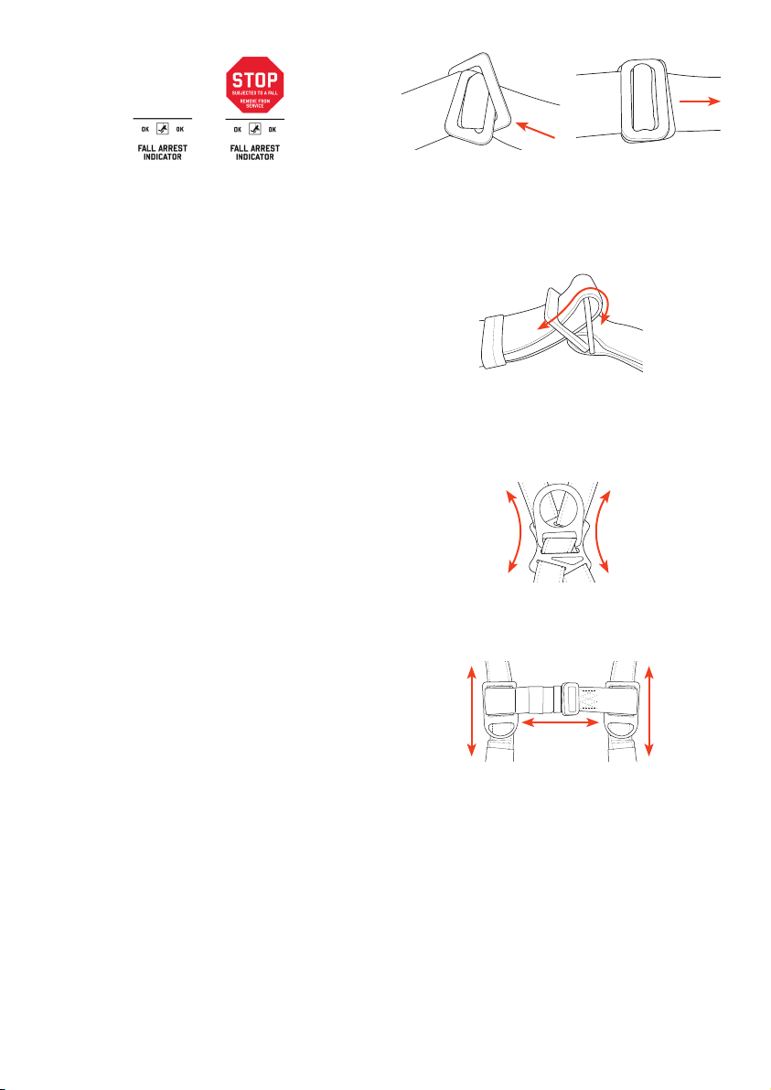
19
Indicadores de detención de caídas: inspeccione cada
uno de los indicadores de detención de caídas ubicados
justo debajo del anillo en D dorsal para detectar signos de
que el arnés de cuerpo completo ha sido sometido a las
fuerzas de la detención de una caída. Los indicadores de
detención de caídas están diseñados de forma que
muestren las letras “OK” antes de la detención de una
caída (Fig. 19A) y se rompan para mostrar una advertencia
luego de que haya ocurrido la detención de una caída
(Fig. 19B). Si el indicador de detención de caídas se
muestra como se ve en la (Fig. 19B), INTERRUMPA
INMEDIATAMENTE EL USO, DESTRUYA
Y DESECHE EL ARNÉS DE CUERPO COMPLETO.
¡ADVERTENCIA! SI EL ARNÉS DE CUERPO COMPLETO
DE ERGODYNE NO CUMPLE CON UN ASPECTO
DEL PROCESO DE INSPECCIÓN, INTERRUMPA
INMEDIATAMENTE SU USO.
AJUSTE DEL ARNÉS DE CUERPO
COMPLETO
¡ADVERTENCIA! UNA PERSONA COMPETENTE DEBE
SELECCIONAR Y DETERMINAR SI EL EQUIPO QUE SE
USE EN COMBINACIÓN CON EL ARNÉS DE CUERPO
COMPLETO DE ERGODYNE COMO PARTE DE UN
SISTEMA PERSONAL DE DETENCIÓN DE CAÍDAS ES
COMPATIBLE. ASEGÚRESE SIEMPRE DE SEGUIR
TODAS LAS INSTRUCCIONES DE CUALQUIER EQUIPO
QUE UTILICE EN COMBINACIÓN CON EL ARNÉS DE
CUERPO COMPLETO DE ERGODYNE COMO PARTE DE
UN SISTEMA PERSONAL DE DETENCIÓN DE CAÍDAS.
¡ADVERTENCIA! NUNCA ENGANCHE UN CONECTOR A
OTRO LUGAR QUE NO SEA EL ANILLO EN D DORSAL.
CUANDO LO ENGANCHE AL ANILLO EN D DORSAL,
EL MECANISMO DE CIERRE DEL CONECTOR DEBE
CERRARSE AUTOMÁTICAMENTE Y SOPORTAR UNA
CARGA MÍNIMA DE 3600 LB. LAS CINCHAS DE LAS
CORREAS QUE SOBREN SE DEBEN ALMACENAR EN
LOS GUARDACORREAS DE CINCHAS DEL ARNÉS.
LOS ELEMENTOS DE SUJECIÓN DEL CORDÓN DE
SEGURIDAD EN LAS CORREAS PARA EL PECHO
SOLO SE DEBEN UTILIZAR PARA SUJETAR EL
CONECTOR DEL PUNTO DE ANCLAJE DEL CORDÓN
DE SEGURIDAD CUANDO EL TRABAJADOR ESTÉ EN
EL SUELO, ANTES DE TRABAJAR EN ALTURAS.
Hebillas pasantes: para conectar las hebillas pasantes,
coloque la hebilla macho en ángulo de forma que las
cinchas puedan pasar a través de ella y de la correa
hembra (Fig. 20). Inserte completamente la hebilla macho
y luego jálela un poco de manera que quede al ras sobre
la hebilla hembra (Fig. 21).
Ajustadores de fricción: los ajustadores de fricción
permiten ajustar la longitud de las correas y asegurar un
ajuste adecuado del arnés de cuerpo completo. Luego de
pasar las cinchas a través de las hebillas, deslice las
hebillas hacia abajo en la correa para apretarlas, o hacia
arriba para aflojarlas (Fig. 22).
Anillo en D dorsal: ajuste el anillo en D dorsal deslizando
la placa para la espalda hacia arriba o hacia abajo en las
correas de las cinchas (Fig. 23). El anillo en D dorsal debe
descansar en medio de los omóplatos.
Correas para el pecho: ajuste la altura de las correas para
el pecho deslizando los elementos de sujeción del cordón
de seguridad hacia arriba o hacia abajo en las correas
para los hombros (Fig. 24). Conecte las correas para
el pecho y posiciónelas en el área media del pecho; 6”
a 8” debajo de la tráquea, pero no debajo del esternón.
Apriete las correas alrededor del pecho usando las
hebillas pasantes y los ajustadores para tensionar las
correas para los hombros.
FIG. 19A FIG. 19B FIG. 20
FIG. 22
FIG. 24
FIG. 23
FIG. 21

20
Guardacorreas: recoja las cinchas que sobren y asegúrelas
debajo de los guardacorreas elásticos del pecho, los
hombros y las correas para los muslos (Fig. 25).
¡ADVERTENCIA! EL ANILLO EN D DORSAL, LAS
CORREAS PARA EL PECHO, LAS CORREAS PARA
LOS HOMBROS Y LAS CORREAS PARA LAS PIERNAS
SE DEBEN AJUSTAR DEPENDIENDO DEL USUARIO.
ASEGURARLAS Y AJUSTARLAS INCORRECTAMENTE
PODRÍA DAR COMO RESULTADO LESIONES GRAVES
O LA MUERTE
CÓMO COLOCARSE EL ARNÉS DE CUERPO
COMPLETO DE ERGODYNE
Los arneses de cuerpo completo son la única forma de
sujeción del cuerpo que se debe utilizar para detener
caídas o como protección en caso de una. Un ajuste
correcto del arnés es fundamental para el desarrollo del
trabajo que se realiza cerca de un peligro de caída. No
permita que el arnés se afloje o se estire durante el uso.
El siguiente procedimiento describe cómo colocarse
correctamente el arnés. Tenga en cuenta: algunos de
los pasos del procedimiento requieren la ayuda de otra
persona. Luego de colocarse el arnés, se recomienda que
otra persona que tenga conocimiento del uso correcto y
seguro del arnés lo inspeccione para determinar si está
correctamente colocado. La ubicación de las correas para
el pecho, las piernas y subpélvica es fundamental para
el buen funcionamiento del arnés de cuerpo completo
durante la detención de una caída. Un arnés mal ajustado
podría no funcionar correctamente durante una caída,
lo que podría dar como resultado lesiones graves o la
muerte.
Paso 1: inspeccione completamente el
arnés de acuerdo con las especificaciones
de este manual. Si el arnés de cuerpo
completo aprueba la inspección, sujételo
del anillo en D y asegúrese de que las
correas no estén retorcidas y que las
hebillas estén abiertas (Fig. 26).
Paso 2: coloque las correas para los
hombros sobre los hombros. Asegúrese
de que el anillo en D dorsal apunte hacia
afuera y ajústelo de forma que descanse
en medio de los omóplatos (Fig. 27).
Paso 3: conecte las correas para los
muslos alrededor de estos, y asegúrese
de que las cinchas no estén retorcidas
(Fig. 28).
Paso 4: ajuste la correas para el pecho a
la altura de la parte inferior de este,
aproximadamente 6-8” desde la parte
superior de los hombros y la tráquea.
conecte las correas para el pecho y
asegúrese de que las cinchas no estén
retorcidas (Fig. 29).
Paso 5: asegure las correas para las
piernas y los hombros de forma que se
ajusten firmemente pero permitan un
rango de movimiento completo. Ajuste
las correas para el pecho de forma que
se tensionen las correas para los
hombros. Las correas para los muslos
nunca deben estar sueltas ni colgar.
Doble las correas que sobren y póngalas
dentro de los guardacorreas de las
correas para los hombros, los muslos y
el pecho (Fig. 30).
¡ADVERTENCIA! ES EXTREMADAMENTE IMPORTANTE
QUE EL ARNÉS DE CUERPO COMPLETO SE AJUSTE
CORRECTAMENTE Y ESTÉ BIEN ASEGURADO. LA
CONEXIÓN ADECUADA DE TODAS LAS HEBILLAS
Y EL AJUSTE DE LAS CORREAS PARA LOS
MUSLOS, HOMBROS Y PECHO SON ESENCIALES.
UN ARNÉS MAL AJUSTADO PODRÍA NO FUNCIONAR
CORRECTAMENTE DURANTE UNA CAÍDA, LO QUE
PODRÍA DAR COMO RESULTADO LESIONES GRAVES
O LA MUERTE.
¡ADVERTENCIA! NUNCA ALTERE NI MODIFIQUE EL
ARNÉS. SELECCIONE SIEMPRE UN ARNÉS QUE
SE AJUSTE CORRECTAMENTE SIN NECESIDAD DE
MODIFICARLO.
¡ADVERTENCIA! EN LAS CORREAS DE TODOS LOS
ARNESES QUE TIENEN HEBILLAS DE FRICCIÓN,
EL EXTREMO DE LA CORREA SE DEBE EXTENDER
MÍNIMO 3” (76 MM) MÁS ALLÁ DE LA CORREA.
¡ADVERTENCIA! SIEMPRE INSPECCIONE
VISUALMENTE LAS CORREAS PARA CERCIORARSE
DE QUE ESTÁN COMPLETAMENTE CERRADAS ANTES
DE USAR EL ARNÉS.
FIG. 25
FIG. 26
FIG. 27
FIG. 28
FIG. 29
FIG. 30
Table of contents
Languages:
Other ERGODYNE Safety Equipment manuals


