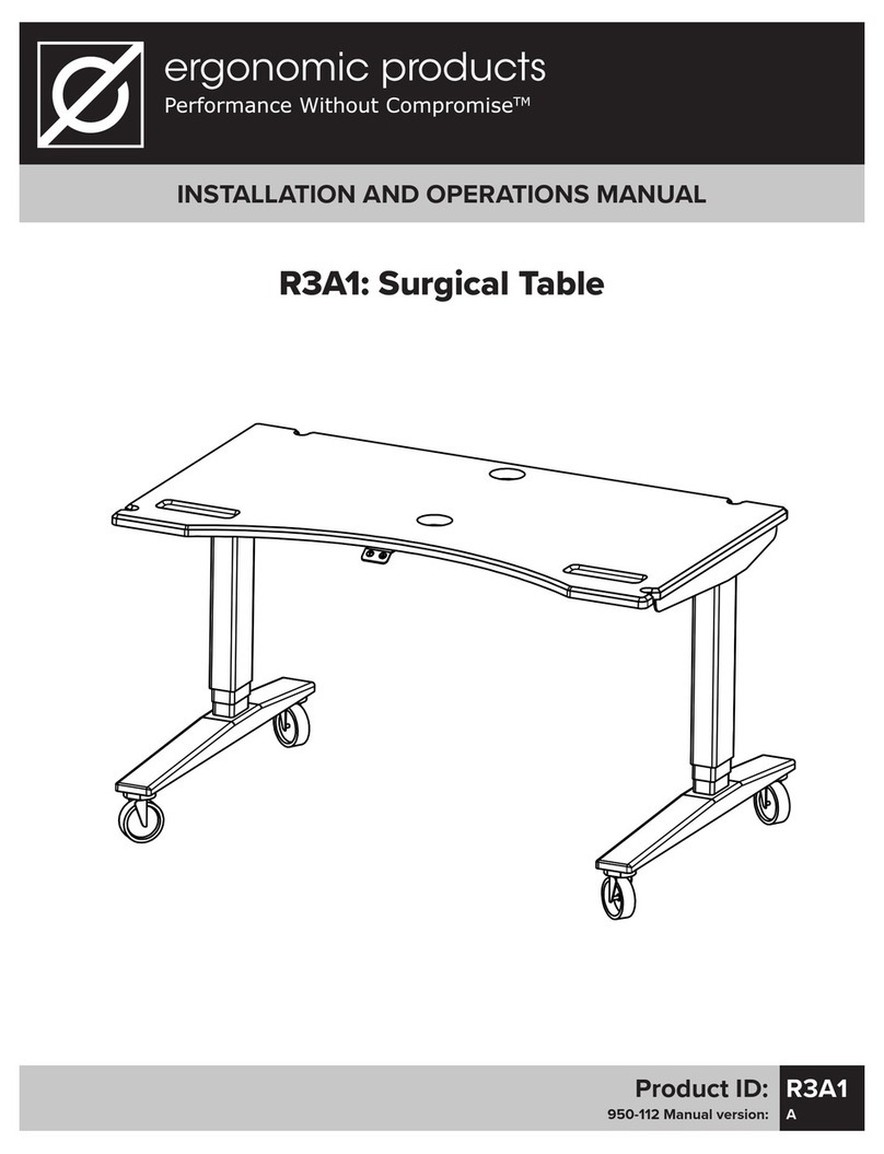
Ergonomic products R3A1 User manual

INSTALLATION AND OPERATIONS MANUAL
Product ID: R3A1
950-112 Manual version: A
R3A1: SurgiLift

950-112 manual ver A
Ergonomic Products • 198 Airport Rd • Fall River, MA 02720 • 866-374-6487
PAGE 2
SurgiLift
Model: R3A1
Thank you for purchasing the Ergonomic Products R3A1 SurgiLift.
Years of research by dentists, engineers, and designers have made this a uniquely eective
product in the industry. We stand behind our equipment, and genuinely believe it to be the
best available on the market.
Should you have any questions regarding the product’s installation or use, please don’t
hesitate to call our customer service specialists at 1-866-ERGO-4-US. We may also be reached
via email at equip@ergonomic-products.com.
We hope that you enjoy the benefits and quality of your new equipment and look forward to
assisting you with your future needs as your practice continues to grow!
—The Ergonomic Products Team
1. Tools Included / Unpacking and Inspecting..................................3
2. Specifications...............................................................................4
3. Installation Prep...................................................................................5
4. Leg Installation.....................................................................................7
5. Electrical Connections.......................................................................11
6. Replacing The Cover..........................................................................13
7. Setup Complete...................................................................................14
8. Using the Uplift Desk Keypad.......................................................15
QUESTIONS?
Call our Customer Service Specialists at:
1-866-ERGO-4-US
CONTENTS:

950-112 manual ver A
Ergonomic Products • 198 Airport Rd • Fall River, MA 02720 • 866-374-6487
PAGE 3
SurgiLift
Model: R3A1
1. Inspect shipping container for visible damage upon arrival. If transit damage is found, contact Ergonomic
Products immediately (this will expedite the corrective process).
2. Use safe lifting procedures to free the product from the container, and remove all packing material and
accessory boxes from shipping container.
3. Lay individual components on clean surface to avoid scratching, and inspect contents. If damage is found,
contact Ergonomic Products immediately.
4. Please keep boxes incase you need to return any items that are damged. We will only accept returns in
its original packing due to the fragile corian table top, we recommend taking pictures as you unpack for this
purpose.
4mm Hex Wrench
Extended Wrench Handle
8-M6 Machine Screws
2 Cord Grommets
1 – REQUIRED TOOLS / UNPACKING AND INSPECTING
SUPPLIED
TOOLS:
2 Leg Screw Guides (A&B)
4mm Ball End Hex Shaft with Knob
BOX 1
BOX 2

950-112 manual ver A
Ergonomic Products • 198 Airport Rd • Fall River, MA 02720 • 866-374-6487
PAGE 4
SurgiLift
Model: R3A1
2 – SPECIFICATIONS
SURGILIFT USE & FEATURES
- 4 Tool Holders
- 2 Recessed burr dedents
- Arched table front for easy access to the
patient
- 4 Rubber 3” Caster wheels
- 1 Power Strip
DESK SPECIFICATIONS
- Height Range 21.5” - 47.75”
- Travel Speed 1.57”/second
- Noise Level 50 dB
- Lifting Capacity 355 lbs
- Current 4 Amps max (during movement)
- Voltage Input 100-120Vac, 50/60Hz, 400w max
21-1/2"
47-3/4"
51-9/16"
25-7/16"
24"
42"
2-1/2"
14-1/2"
21"
24"
42"
Rubber
Casters
Power Strip
Up/Down
Controller

950-112 manual ver A
Ergonomic Products • 198 Airport Rd • Fall River, MA 02720 • 866-374-6487
PAGE 5
SurgiLift
Model: R3A1
1. “Box #1” contains the “SurgiLift” and the “Tools and Hardware” box. Remove and set aside the Foam Bars,
Remove the Tools and Hardware Box and set aside.
2. “Box #2” contains the legs; remove and discard the Foam Bars. Remove each leg and set aside for assembly.
NOTE: Please retain all packing material and boxes should the unit need to be returned.
3 – INSTALLATION PREP
3. Open the Tools and Hardware Box and set aside the (8) - M6 Machine Screws, the (1) 4mm Hex Wrench with
Extended Handle, (2) leg screw guides A and B, (1) 4mm ball end hex shaft with knob, (2) cord grommets.
Box #1 - Table Top
Remove Tools and Hardware
Box #2 - Legs
Remove 3 Foam Bars

950-112 manual ver A
Ergonomic Products • 198 Airport Rd • Fall River, MA 02720 • 866-374-6487
PAGE 6
SurgiLift
Model: R3A1
4. With a partner, lay the table upside down on a protected surface as to not damage the top working surface.
This exposes the frame and the electronics cover.
3 – INSTALLATION PREP CONT’D
Front View
Back View
5. Remove plastic cover by slightly spreading long wall and pivot cover away to clear the black pins (Fig 5.1).
Once clear, repeat on opposite side. With cover removed, it will reveal the electronic components (Fig 5.2).
Fig 5.1 Fig 5.2
Black Pin
Long Wall

950-112 manual ver A
Ergonomic Products • 198 Airport Rd • Fall River, MA 02720 • 866-374-6487
PAGE 7
SurgiLift
Model: R3A1
6. When installing the leg, please note the orientation should be as shown with the long extended foot (Fig 6.1)
pointing towards the table front (Fig 6.2). Install the leg between the rails as shown in (Fig 6.3).
4 – LEG INSTALLATION
Fig 6.1
Fig 6.2
Fig 6.3
Long Extended
Foot

950-112 manual ver A
Ergonomic Products • 198 Airport Rd • Fall River, MA 02720 • 866-374-6487
PAGE 8
SurgiLift
Model: R3A1
7. Insert screw guide “A” into access hole adjacent to yellow dot (Fig 7.1). Line up points of “A” on dot guide.
Remove one screw from bag. Using the 4mm ball hex shaft driver, attach screw to ball end of tool (Fig 7.2). Place
screw into guide, turn tool clockwise until finger tight (Fig 7.3). Slide guide out with tool (Fig 7.4) repeat operation
on opposite side of leg.
4 – LEG INSTALLATION CONT’D
Fig 7.1 Fig 7.2
Fig 7.3 Fig 7.4

950-112 manual ver A
Ergonomic Products • 198 Airport Rd • Fall River, MA 02720 • 866-374-6487
PAGE 9
SurgiLift
Model: R3A1
8. Insert “B” screw guide adjacent to GREEN B dot (Fig 8.1). Insert screw guide “B” into access hole adjacent to
green B dot. Remove one screw from bag using the 4 mm ball hex shaft driver (Fig 8.2). Attach screw to ball end
of tool. Place screw into guide(Fig 8.3). Turn tool clockwise until finger tight. Slide guide out with tool (Fig 8.4)
4 – LEG INSTALLATION CONT’D
Fig 8.1 Fig 8.2
Fig 8.3 Fig 8.4

950-112 manual ver A
Ergonomic Products • 198 Airport Rd • Fall River, MA 02720 • 866-374-6487
PAGE 10
SurgiLift
Model: R3A1
8a. Using 4mm right angle hex driver with extended handle (Fig 8.5), Tighten the 4 screws down firmly (yellow
and green dots) (Fig 8.6). Repeat procedure to instal leg on opposite end of table.
4 – LEG INSTALLATION CONT’D
Fig 8.5 Fig 8.6

950-112 manual ver A
Ergonomic Products • 198 Airport Rd • Fall River, MA 02720 • 866-374-6487
PAGE 11
SurgiLift
Model: R3A1
9. Once both legs are installed each leg has an electrical connector. The 6-pin male connector needs to be
plugged into the 6-pin female connector on one end of the leg (Fig 9.1 & 9.2). Tuck and secure wires as shown in
(Fig 9.3).
5 – ELECTRICAL CONNECTIONS
Fig 9.3
Fig 9.2Fig 9.1

950-112 manual ver A
Ergonomic Products • 198 Airport Rd • Fall River, MA 02720 • 866-374-6487
PAGE 12
SurgiLift
Model: R3A1
10. On the opposite leg the 6-pin male connector plugs into the female 6-pin connector on the power box (Fig
10.1) Tuck and secure wires as shown in (Fig 10.2)
5 – ELECTRICAL CONNECTIONS CONT’D
Fig 10.2
Fig 10.1

950-112 manual ver A
Ergonomic Products • 198 Airport Rd • Fall River, MA 02720 • 866-374-6487
PAGE 13
SurgiLift
Model: R3A1
11. With the legs secured and the electrical connections made, leave the tail of black power cord out as
shown in (Fig 11.1). Replace the plastic cover by starting on the power brick side, align the cover side holes
to the black pins on the frame (Fig 11.2). Spread the cover apart and pivot to the opposite side and align to
black pins making sure front wire goes through grommet hole (Fig 11.3).
6 – REPLACING THE COVER
Fig 11.2
Fig 11.1
Fig 11.3
Black
Power Cord
Power Brick

950-112 manual ver A
Ergonomic Products • 198 Airport Rd • Fall River, MA 02720 • 866-374-6487
PAGE 14
SurgiLift
Model: R3A1
12. With the cover on securely (Fig 12.1), flip table over onto casters with the help of a partner. Insert the cord
grommets (Fig 12.2). Your Surgical Table is complete (Fig 12.3).
7 – SETUP COMPLETE
Fig 12.1
Fig 12.2
Fig 12.3
Insert Cord Grommets

950-112 manual ver A
Ergonomic Products • 198 Airport Rd • Fall River, MA 02720 • 866-374-6487
PAGE 15
SurgiLift
Model: R3A1
8 – USING THE KEYPAD
13. Check your table surroundings to make sure there will be no obstacles in the table’s path and that
all cords are long enough to accommodate the vertical motion of your table. Plug your table into a
120V outlet.
Initial Table Reset Procedure:
Press and hold the DOWN button for 10 seconds, then release the button. Press and hold the DOWN button
again, the desk will lower a little, then rise a little, and then stop. Release the button. Your SurgiLift is now
ready to use!
UP DOWN
Other manuals for R3A1
1
Table of contents
Other Ergonomic products Medical Equipment manuals
Ergonomic products
Ergonomic products Safe-T-Shield User manual
Ergonomic products
Ergonomic products Safe-T-Shield VacTrac User manual

Ergonomic products
Ergonomic products 32 INWALL COMFORT MEDIA User manual

Ergonomic products
Ergonomic products D1C Series User manual

Ergonomic products
Ergonomic products C1A1 User manual

Ergonomic products
Ergonomic products R3A1 User manual