888-SV-22DL-00 rev C
10
Equipment Changes and Cart Transfers
Always anchor the riser to the tower BEFORE making changes to cart such as:
• removing or adding equipment
• preparing the cart for transit to another site
See step 2 on page 2 for more information.
Cleaning and Maintenance
The following procedures are not guaranteed to control infection. The hospital infection control admin-
istrator or epidemiologist should be consulted regarding cleaning procedures and processes.
To avoid risk of electric shock, do not expose electrical components to water, cleaning
solutions or other potentially corrosive liquids or substances.
Do not immerse Cart or Cart components in liquid or allow liquids to ow into the Cart.
Wipe all cleaners o surface immediately using a damp cloth. Thoroughly dry surface after
cleaning.
Do not use ammable cleaners on Cart surfaces due to close proximity of electrical
power and equipment.
All paints and plastic Cart components will withstand cleaning by most commonly used, diluted, non-
abrasive solutions such as quaternary ammonia compounds, ammonia enzyme cleaners, bleach or
alcohol solutions.
• Pen and permanent and dry erase markers can be removed with 91% isopropyl alcohol and a soft
cloth.
• Iodine stains can be removed with commonly used cleaners and a soft cloth.
• Never use steel wool or other abrasive materials that will damage the surface nish.
It is recommended that any cleaning solution be tested on a small, inconspicuous area to ensure
surface is not harmed.
Adjustment, Service, Replacement - DO NOT attempt to adjust, service or re-
place any part of the StyleView Cart unless directed to do so through Ergotron-approved documenta-
tion (i.e. installation instructions). Only Ergotron, Inc. or an Ergotron-certied entity may adjust, service
or replace StyleView Cart components. If any component on the Cart is missing or damaged, the Cart
must not be used, contact Ergotron Customer Care immediately to request a replacement part.
Cables - Keep cables neatly organized on the Cart (a variety of solutions are provided with
your cart for this purpose). Excess cables should be routed away from moving components with cable
clips. Review Cable Routing section of this guide, or contact Ergotron Customer Care for more informa-
tion.
Casters - Check casters periodically to make sure they are clean and free of debris that would
prevent smooth travel. Avoid moving Cart across uneven, dirty or damaged surfaces.
Customer Equipment- Make sure equipment is balanced and mounted se-
curely to Cart. Do not reposition Cart components on riser or tower unless instructed to do
so in the installation instructions. Moving Cart components too high or too low on the Riser
may create an unstable condition, leading to equipment damage or even personal injury.
Contact Ergotron Customer Care for information about moving Cart components.
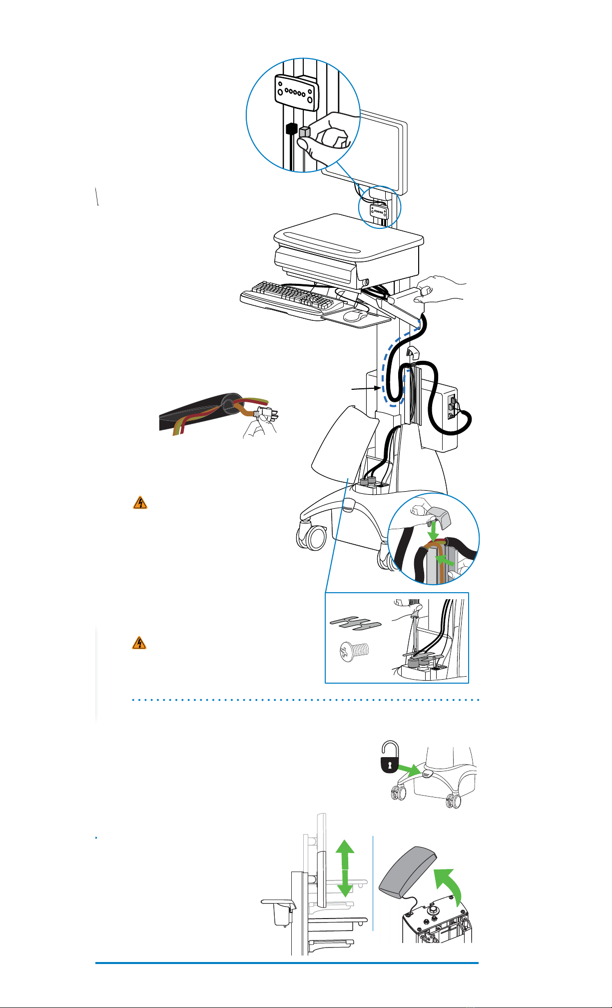
Cart Stability - When moving cart, the riser MUST be in the lowest position and the lift
brake MUST be locked to protect against possible tipping. Failure to lock the riser in the lowest position
with the lift brake may result in personal injury or equipment damage.
CAUTION: The lift brake helps stablilize the worksurface and keyboard tray during normal
use but it DOES NOT increase load capacity. DO NOT load riser with equipment totalling more
than the maximum weight capacity specied by Ergotron. Ensure optimum lift function by test-
ing and if necessary, re-adjusting tension whenever the weight mounted to the riser changes
(i.e., equipment is removed or added). See "Set Riser Lift Tension" adjustment instructions in step
9 on pgae 5.
CAUTION: Do not operate StyleView Cart with missing or damaged components! Do not
remove, modify or substitute Cart components without consulting Ergotron. If you encounter
problems with Cart installation or operation, contact Ergotron Customer Care.
CAUTION: DO NOT overtighten fasteners. Overtightening may cause damage to your
equipment.
CAUTION: Riser is under spring tension. Rapid rise or fall of riser can occur prior to
counterbalancing. Lock riser down with Brake before removing Riser Anchor Screws or loading/
unloading equipment. Do Not put yourself in path of movable riser or mounted components until
riser is properly counterbalanced. Failure to comply with this caution may result in equipment
damage or personal injury.
CAUTION: DO NOT loosen, tighten or remove any other nuts or bolts on the riser or top of
tower. Tampering with nuts or bolts may result in an unstable Cart, leading to equipment damage
and/or personal injury.
WARNING: Unlock Lift Brake before moving work surface! Moving work surface while Lift
Brake is locked may cause serious damage to Lift Engine.
WARNING: In the event that repair of the StyleView Cart is needed, contact Ergotron Cus-
tomer Care immediately. Cart repair can only be performed by Ergotron, Inc. or by an Ergotron
authorized agent.
CAUTION:
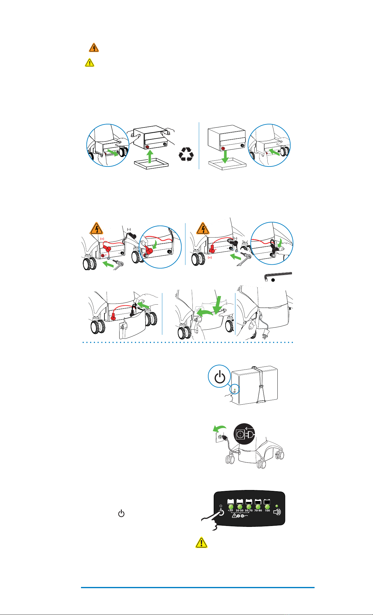
Route cables on Cable Channel (right) side of Cart only.
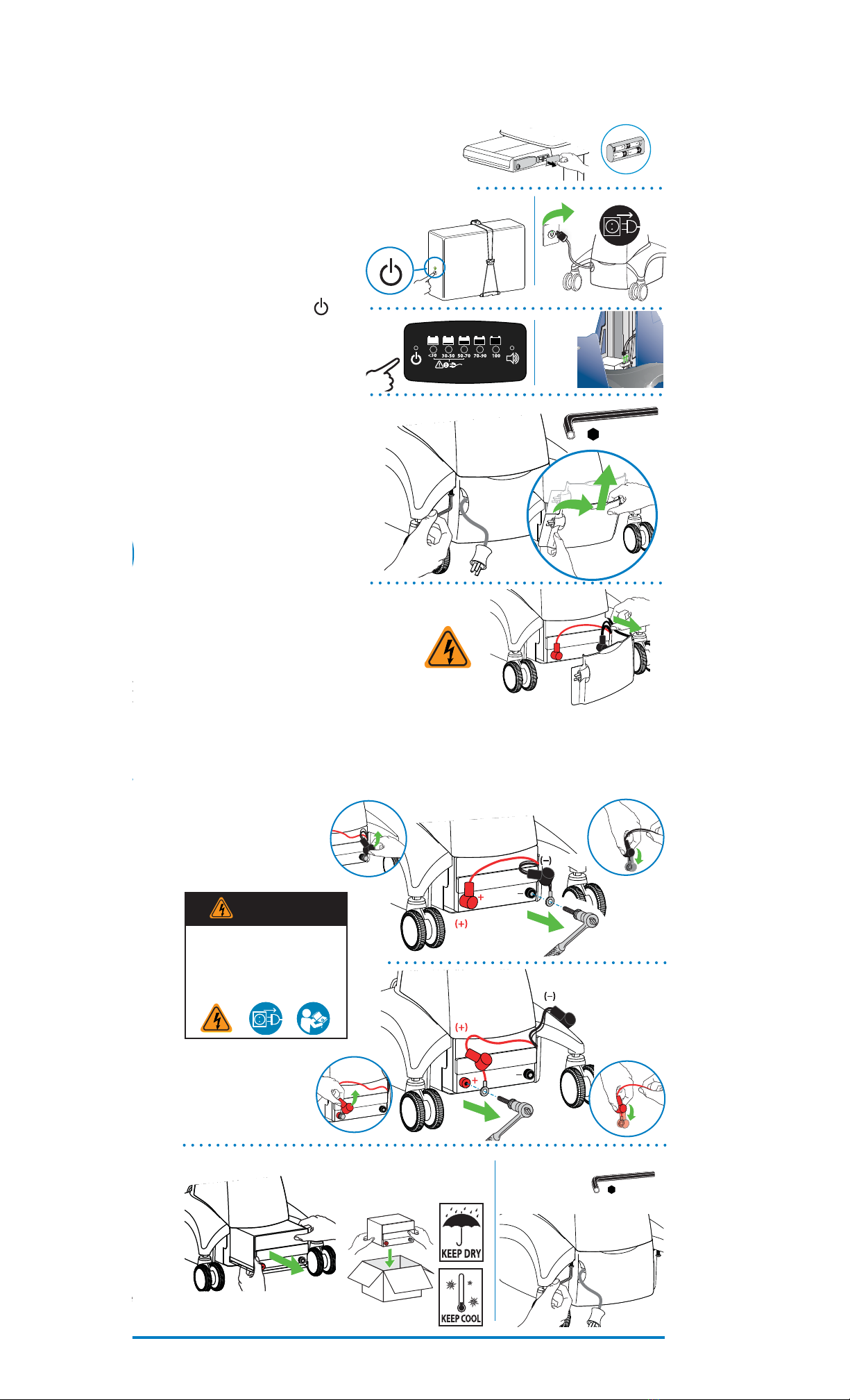
Do not store power brick
inside base covers. Storing power brick inside base covers may damage electrical wires and interfere with
riser operation, resulting in damage to both Cart and mounted equipment or injury from electrical shock.
Safety Alerts Associated with this Product
The following Warnings/Cautions appear in this reference guide or on the cart:
NOTE: Failure to adhere to these guidelines may result in equipment damage or personal injury.
Cart Safety Guidelines