LBI-39055
7
• Audio Tower-to-Boom/Gooseneck PTT and
Monitor Switches (if used)
• Audio Tower-to-Footswitches (if used)
• Audio Tower-to-Volume Controller Box (if used)
• Audio Tower-to-Speakers (if used)
• PC, Video Display Monitor and Audio Tower AC
Power Connections
In addition, the following interconnections are required
for optional equipment, if employed:
• Audio Tower-to-Recorder Equipment
• Audio Tower-to-Pager
• Audio Tower-to-External Equipment Controlled by
Relay Form-A Contacts
• Audio Tower-to-Call Director
NOTE
Unless otherwise noted, all procedures in this
manual should be performed in the order presented.
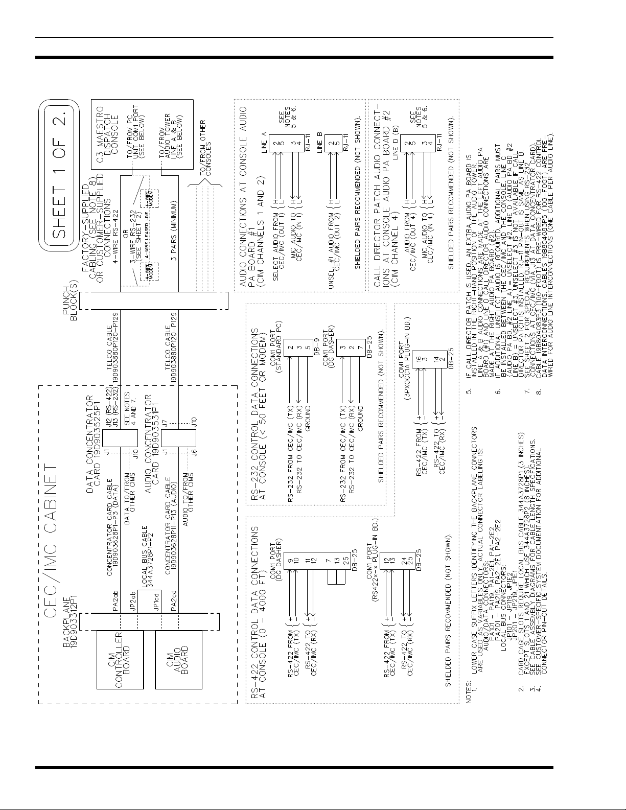
CEC/IMC INTERCONNECTIONS
The C3 Maestro console interfaces to the CEC/IMC via
a full-duplex serial control data link and a 4-wire audio
connection. In addition, each unselect speaker requires an
additional 2-wire connection from the CEC/IMC. Also, if
the console is interfaced to a Call Director for Call Director
telephone patch operations, an additional 4-wire audio link
between the C3 Maestro and the CEC/IMC is required. See
Figures 1 and 8. As shown in Figure 8, all CEC/IMC
interconnections are made at Concentrator Cards. These
cards are located at the back of the CEC/IMC cabinet.
CEC/IMC Concentrator Card pin-out details are listed
on the customer-specific system documentation print-outs.
These print-outs are included with the CEC/IMC when it
ships from the factory. See the CEC/IMC Digital Audio
Switch Customer-Specific System Documentation
maintenance manual, LBI-38939 for sample print-outs and
complete print-out explanations.
Control Data Link
Either an RS-422 (four-wire) or an RS-232 (three-wire)
serial control data link may be employed. RS-422 control
data interfacing is recommended and in most all
installations, it is used for co-located console
interconnections. RS-232 has poorer noise performance than
RS-422 and therefore, it should never be used for cable runs
more than 50 feet in length.
If required for a remote console installation, full-duplex
4-wire data modems can be used between the C3 Maestro
and the CEC/IMC. See the following subsection for
additional remote console wiring and modem configuration
details.
At the C3 Maestro, control data connections terminate
at the PC's COM1 serial port. On the CEC/IMC side, the
console's control data connections are made at a Data
Concentrator Card. As shown in Figure 8A, punch blocks
may be installed between the CEC/IMC and the console.
Also shown in the figure, a Concentrator Card Cable
interconnects the Data Concentrator Card to the CIM
Controller Board via the CEC/IMC Backplane.
All Data General (DG) Dasher computers are factory
equipped with a built-in COM1 serial port on the main
board that can be wired for RS-422 or RS-232 operation.
The connector is a DB-25 type. See Figure 8A.
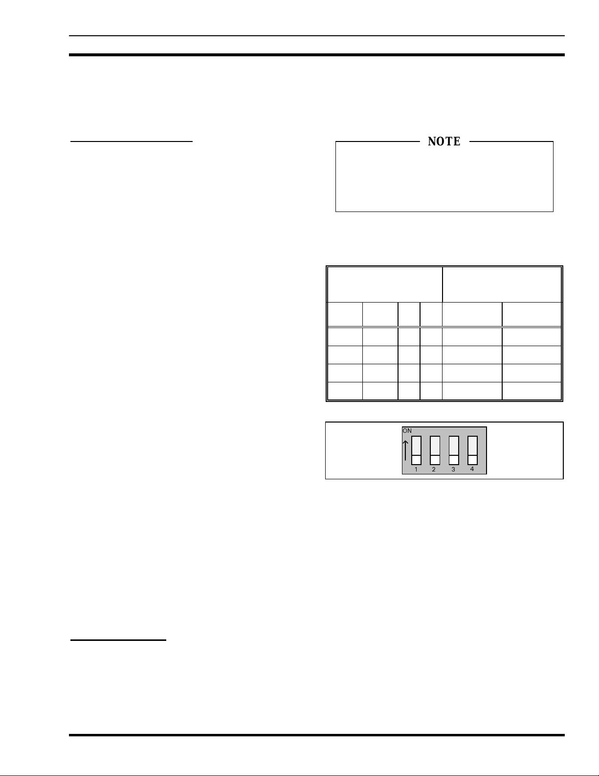
Computers not equipped with a main board RS-422
capable COM1 port normally have a plug-in RS-422 board
installed in an expansion slot. This board has a DB-25
connector at its rear plate. Approved RS-422 plug-in board
model numbers include RS422AT-P, RS422I-P and
3PXOCC1A. An RS422x-x board (part number
344A3927P38) can easily be identified by the presence of
two LED indicators visible on its rear plate. If a plug-in RS-
422 board is used, the PC's main board COM1 port must be
disabled. This is done via a DIP switch, jumper, or a BIOS
set-up program. For COM1 port enable/disable
configuration details, refer to the section entitled
"SOFTWARE INSTALLATION AND SET-UP
PROCEDURE", subsection "PC CMOS SET-UP
PROGRAM" later in this manual, and the PC
manufacturer's documentation.
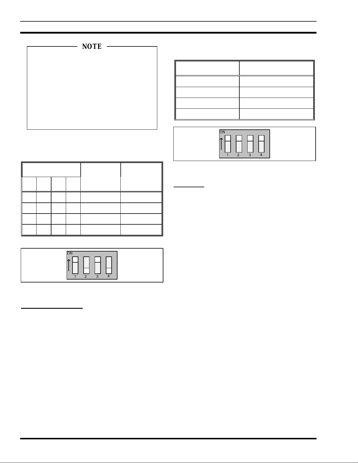
Factory-installed RS422x-x (344A3927P38) or
3PXOCC1A plug-in boards are configured correctly before
the PC ships from the factory. This configuration includes
disabling the PC's main board COM1 port per
manufacturer's instructions.
RS422x-x board configuration is:
Address Switches A3-A9 All On (RS422AT-P)
Address Switches A3-A9 All Off (RS422I-P)
Interrupt Jumper IN4
LD GND Jumper In
LD Jumper In
DX Jumper In
SX Jumper Out
HDX Jumper Out
IMPORTANT NOTE