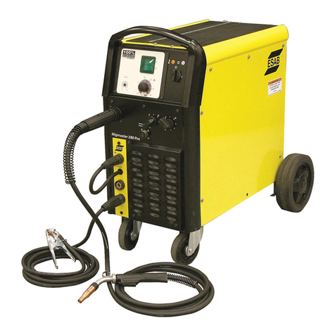
ESAB AK 400 User manual

AK 400
AK 600
Fully Thyristorised MIG/MAG
Welding Power Source
Instruction manual

AK400, AK 600
FULLY THYRISTORISED MIG/MAG WELDING POWER SOURCE
Instruction manual
For
Installation, Operation & General maintenance

CONTENTS
Item Page No.
SAFETY
1-2
ASSEMBLING 3
ACCESSORIES LIST 3
RATING 4
CAUTIONS FOR INSTALLATION 5
INSTALLATION 6
WELDING OPERATIONS 7
JIG TERMINALS AND SWITCHING TERMINALS 8-9
IN WELDING POWER SOURCE. OPERATIONS
MAINTENANCE & INSPECTION 10
AFTER SALES SERVICE 11
FAULT FINDINGS 12-14
OVERALL CIRCUIT DIAGRAM 15, 16
RECOMMENDED LIST OF SPARE PARTS 17
WELD DEFECTS AND POSSIBLE CAUSES 18-19

SAFETY
Users of ESAB welding equipment have the ultimate responsibility for ensuring that
anyone who works on or near the equipment observes all the relevant safety
precautions. Safety precautions must meet the requirements that apply to this type of
welding equipment. The following recommendations should be observed in addition to
the standard regulations that apply to the workplace.
Trained personnel well acquainted with the operation of the welding equipment must
carry out all the work. Incorrect operation of the equipment may lead to hazardous
situations, which can result in injury to the operator and damage to the equipment.
1. Anyone who uses the welding equipment must be familiar with:
• its operation
• location of emergency stops
• its function
• relevant safety precautions
• welding
2. The operator must ensure that:
• no unauthorized person is stationed within the working area of the equipment
when it is started up.
• no one is unprotected when the arc is struck
3. The workplace must:
• be suitable for the purpose
• be free from drafts
4. Personal safety equipment
• Always wear recommended personal safety equipment, such as safety glasses,
flameproof clothing, and safety gloves.
• Do not wear loose—fitting items, such as scarves, bracelets, rings, etc., which
could become trapped or cause burns.
5. General precautions
• Make sure the return cable is connected securely.
• Only a qualified electrician may carry out work on high voltage equipment.
• Appropriate fire extinguishing equipment must be clearly marked and close at
hand.
• Lubrication and maintenance must not be carried out on the equipment during
operation.
1

Read and understand the instruction manual before installing or operating.
ESAB can provide you with all necessary welding protection and accessories.
WARNING
Arc welding and cutting can be injurious to yourself and others. Take
precautions when welding.
Ask for your employer’s safety practices which should be based on manufacturers’
hazard data.
ELECTRIC SHOCK – Can kill
• Install and earth the welding unit in accordance with applicable
standards.
• Do not touch live electrical parts or electrodes with bare skin, wet
gloves or wet clothing.
• Insulate yourself from earth and the workpiece.
• Ensure your working stance is safe.
FUMES AND GASES – Can be dangerous to health
• Keep your head out of the fumes.
• Use ventilation, extraction at the arc, or both, to take fumes and gases
away from your breathing zone and the general area.
ARC RAYS – Can injure eyes and burn skin.
• Protect your eyes and body. Use the correct welding screen and filter
lens and wear protective clothing.
• Protect bystanders with suitable screens or curtains.
FIRE HAZARD
• Sparks (spatter) can cause fire. Make sure therefore that there are no
inflammable materials nearby.
NOISE – Excessive noise can damage hearing
• Protect your ears. Use earmuffs or other hearing protection.
• Warn bystanders of the risk.
MALFUNCTION – Call for expert assistance in the event of malfunction.
PROTECT YOURSELF AND OTHERS!
CAUTION!
This product is solely intended for arc welding
Do not dispose of electrical equipment together with normal waste!
In accordance with national law, electrical equipment that has
reached the end of its life must be collected separately and returned
to an environmentally compatible recycling facility. As the owner of
the equipment, you should get information on approved collection
systems from the local representative. By applying this Directive you
will improve the environment and human health
2

A. ASSEMBLING
The complete Installation should consist of the following items:
Description
Type
Quantity
1. Welding Power
Source
AK 400
OR
AK 600
1
2. Wire Feeder &
Remote Control
Unit
SERVO WIREFEEDER- I WITH
ACCESSORIES & REMOTE CONTROL
UNIT – RC AK 400
OR
SERVO WIREFEEDER- II WITH
ACCESSORIES & REMOTE CONTROL
UNIT – RC AK 600
1
B. ACCESSORIES LIST FOR AK 400 / AK 600 THYRISTORISED
MIG/MAG WELDING POWER SOURCES
Fuse, element 5A 1 piece
Fuse, element 8A 1 piece
Instruction Manual 1 piece
3

C. RATING OF AK 400 / AK 600 THYRISTORISED MIG/MAG
WELDING POWER SOURCES
CHARACTERISTICS CONSTANT POTENTIAL TYPE
INPUT:
SUPPLY VOLTAGE, PHASE
& FREQUENCY
415 V ±10%, 3 PHASE, 50 HZ, AC
MAXIMUM INPUT CURRENT 31 Amps 55 Amps
MAXIMUM RATING 20.7 KVA 40 KVA
OUTPUT:
OUTPUT CURRENT RANGE DC 60A-400A DC 60A-600A
Maximum output Current at
60% Duty Cycle
400 Amps 600 Amps
Maximum continuous current
at 100% Duty cycle
310 Amps 470 Amps
Open circuit voltage (Max) 53 Volts DC 63 Volts DC
Type of Welding Voltage &
Current control
Stepless through remote control
Unit RC AUTO K 400 &
RC AUTO K 600
Class of Insulation CLASS H
COOLING FORCED AIR COOLED
Approximate dimension
(LENGTH X WIDTH X
HEIGHT) in mm
675X 350 X 690 617 X 455 X 850
Weight (Approximate) 110 Kgs. 155 Kgs.
4

D. CAUTIONS FOR INSTALLATION
a) Capacity of Equipment
Input Voltage
AC 415 V ±10%
Number of Phase &
Frequency
3 phases, 50 HZ
AK 400 AK 600
Maximum rating of
Equipment
20.7 KVA 40 KVA
Capacity of Fuse (B Class) 32 Amps 63 Amps
Input Cable More than
8 mm2 More than
14 mm2
Output Cable More than
38 mm2
More than
60 mm2
− Provide a Switch Box for every Welding Power Source, and use designated
fuse
− Tolerance of Power Voltage Variation is ±10% of rated input voltage.
− 100 Amps MCB to be used as alternative to SFU.
b) Installation place
− Install in the place where less moisture and dust exist. Avoid direct sunlight and
rain, and maintain ambient temperature within –10o to 45o C as much as
possible.
− Keep the welding power source at least 20 cm. away from the wall (if any).
− In case of installation of more two units side by side, a distance of more than 20
cm. is recommended between the two power sources.
− Keep the Gas Cylinder on a separate stand.
− Use a shield to protect the welding arc in case of excessive air draft.
5

c) Ventilation
Adequate ventilation is recommended at the place of installation. For
example the following guideline should be followed:
a) In case of the area is more than 300 square meters (per unit), no
ventilation is required, provided the room is not completely air tight.
b) In case of the area is less than 300 square meters, the torch is used in
fixed condition and the welding is continuously performed, adequate
ventilation is recommended with the help of vent fan or exhaust duct.
E. INSTALLATION ITEMS OF AK 400 / AK 600
While performing the grounding work, it is recommended that a skilled electrician does
the work.
No. Items No. Items
1.
2.
3.
4.
5.
6.
7.
8.
9.
10.
11.
Remote Control Unit
RC AUTO K 400 / RC AUTO K 600
Wire Feeder
SERVO WIREFEEDER-I / SERVO
WIREFEEDER-II
Welding Torch PSF 400 / PSF 500
Base Metal
Gas Regulator
Gas Cylinder
Switch Box
Connector for Remote Control
Gas Outlet
Connector for Wire Feed
Terminal for work
12.
13.
14.
15.
16.
17.
18.
19.
20.
21.
22.
Terminal for Wire feeder (+)
Gas Inlet
Connector for CO2 Heater
Control cable for RC
AK 400 / RC AK 600
Welding Cable
Gas Hose
Welding Cable
Control cable for Wire feeder
Gas Hose
Cable for CO2 Heater
Input Cable
6

F. WELDING OPERATIONS
The welding operation can be adjusted from the front operation panel of the power
source and remote control unit.
Gas Supply:
To check the gas supply before welding, set the SHIELD GAS switch to CHECK
position. The shielding gas will start flowing. After confirmation, release the switch and
it will automatically return to WELD position.
Welding method:
Set the switch at CO2or Ar-CO2depending on the Shielding Gas used for GMA
welding.
Self hold:
When the Self hold / Crater switch is ON, the arc is produced while the torch switch is
ON and then the self hold is maintained even though the torch switch is turned OFF,
and the crater control condition will start functioning if the torch switch is triggered ‘ON’
for the second time.
Crater control function
An Arc Crater normally formed at the end of the welding can be filled without any
defect by adjusting the crater current and crater voltage knobs on the front panel of
the Power Source.
Remote Control unit
Adjust welding voltage and current from the Remote Control Unit as per following
guidelines:
a) Welding Current Adjustment:
Set the welding current by turning the current adjustment knob and adjust at
the proper graduated value of the current. However, for fine-tuning, set the
welding current from the ammeter in the front panel of the Power Source, by
generating an experimental Arc.
7

b) Welding Voltage Adjustment:
Adjust the welding voltage by turning the voltage adjustment knob of the
Remote Control Unit. Set at a proper graduation of the voltage value. However,
the voltage value indicated in the remote Control Unit is indicative only.
Therefore, set a proper value from the voltmeter of the front panel by
generating experimental arc.
G. JIG TERMINAL AND CHANGEOVER TERMINALS IN WELDING
POWER SOURCE
Jig Terminals
• These are the signal terminals, which are convenient to use with welding
jigs such as a welding, turn table, etc and terminals are also provided to
operate a gas valve separately.
• The Jig terminals are fixed on Printed Circuit Board of welding power
source. Printed Circuit Board will be visible when front panel cover is
removed.
8

Preflow ON and OFF Changeover Terminals
• A preflow timer (about 0.6 sec) is built in the control circuit. The Machine
comes with the Preflow set at OFF position.
• The preflow of the shielding gas can made be either ON or OFF by
changeover terminals on Printed Circuit Board.
FTT “ON” and “OFF” Changeover terminals
• FTT circuit is provided to stop the growth of globule at the end of the wire to
enhance the arc striking while restarting the welding. The FTT circuit can be
turned ON or OFF by the changeover terminal on Printed Circuit Board.
• FTT is set at ON as standard.
• Under special welding conditions where the welding is too frequently
repeated, a spark can occur if the FTT is “ON”, due to the end of the wire
touching the base metal immediately after welding (due to extended burn
back time limit). In such case, FTT is to be set at OFF.
I. ACTION
• When crater unit / self hold function is turned on:
1. When the pre-flow is turned ON, the welding voltage and wire feed action is
delayed by about 0.6 second.
The preflow is turned OFF, while supplied from the factory.
2. The dotted line portion indicates an action when FTT is OFF.
3. About 25 seconds after releasing the torch switch, the power saving circuit is
activated to turn off the electromagnetic contactor. Energy saving circuit is
incorporated in the unit.
9

• When the self-hold function is turned off.
H. MAINTENANCE & INSPECTION
The maintenance and inspection should be carried out only after the switches in the
switch box are turned OFF.
Try to maintain and inspect the set regularly as per the following guidelines:
a) Regular Inspection
(Every 3-6 months, depending on operation frequency):
Inspection Portion Inspection Point Maintenance Method
Fuse Box
Fastening & looseness at
the Connection.
Confirmation of proper
fuse.
Refer to the Equipment
Capacity
Input and Output
Terminals
Fastening & looseness at
the Connection.
Confirmation of Insulation.
Fasten first and Tape
Electro-magnetic
Contactor
Confirmation of Abrasion
at Contact Points.
Replace with new ones.
Interior of Welding Power
Source
Sedimentation of Dust.
Trace of Overheat
Blow off dust with
Compressed Air.
10

b) Cautions for Insulation Voltage-Proof Test & Insulation Resistance
Measurement Test:
Careless execution of Dielectric Strength test and Insulation Resistance Measurement
will cause damage to the power source, since the thyristors, transistors and other
semiconductor parts are widely used in the unit. When these are to be performed in
accordance with the bylaws of your company, the following points should be kept in
mind: -
• Take off the cables from the switch box that are connected to the three input
terminals and short circuit the three input terminals.
• Take off the cable that is connected to two output terminals and short circuit the
two output terminals.
• Short circuit between anode and cathode of thyristors SCRI-6
• Remove the two grounding conductors. (Take off the side panel, and then remove
one conductor nearby the electro-magnetic contactor and also the other conductor
ground to leg of the DC reactor).
I. AFTER SALES SERVICE
In case of any abnormality observed during usage of equipment, which could not be
rectified at site, please contact immediately Area Sales Manager of the nearest unit of
ESAB with the following details:
1) Serial Number of the equipment and type
2) Nature of the complaint with the relevant details, if possible and the details of
Input Supply
3) Date of purchase of the equipment and the date of commissioning.
The qualified and trained service team of ESAB, located at the ESAB Office, render
the after sales service to the customers and also assist in proper selections of Welding
Equipment & consumables for various applications.
11

J. FAULT FINDING
Check points in case of Abnormal Operation
Fault Possible Cause Rectification
Control Fuse is blown Replace with the rated fuse1. Welding is
automatically
stopped, and the
“INDICATOR WARN”
lamp is ON
The Duty Cycle or welding
current are higher than
specified limits.
Wait and allow the Cooling Fan
to rotate. Keep the Fan running
more than 10 minutes after the
abnormal Indication Lamp is
turned OFF, and do not start the
welding. While restarting
welding, lower the welding
current or duty cycle. Avoid the
welding operation while
indicator Lamp “WARN” is
repeatedly ON.
Power Switch is in OFF position Turn the power ON.
Single phase Operation Check Fuses, power switch in
the switch box.
The set value of the welding
current at Remote Control unit
is in the lowest.
Increase current value by
turning clockwise the current
adjustment knob.
The Motor fuse is blown. Replace fuses with the rated
ones.
Disconnection of the Wire
Feeder’s control cable or
imperfect contact of the
connector.
Check for continuity using a
multimeter. Machine has to be
kept switched OFF during
continuity test
2. Wire does not feed
even pressing the
Torch Switch
Fault of the Control PCB /
Crater PCB
Replace Control PCB / Crater
PCB
12

Fault Possible Cause Rectification
Fault of the Torch Switch or
disconnection of the control
cables.
Check for continuity using a
multimeter. Machine has to be
kept switched OFF during
continuity test
3. The wire feeds in
inching but no feeding
when the Torch
Switch is pressed
“ON”
Fault of main PCB / Crater PCB Replace main PCB / Crater
PCB
The Power Switch is in OFF
position
Turn the Power Switch ON.
The Power Fuses in the Supply
lines are blown.
Check the Switch Box’s fuse
and Power Fuse.
4. When the Torch
Switch is pressed,
there is no wire
feeding and output
voltage is not
available. Failure of the Torch Switch or
disconnection of the control
cable.
Check for continuity using a
multimeter. Machine has to be
kept switched OFF during
continuity test
Fault of the Current Control
Potentiometer in Remote
Control Unit.
Check and replace
Fault of the Control PCB /
Crater PCB
Replace Control PCB / Crater
PCB
Fasten the plug socket firmly
5. The current
adjustment does not
work.
Disconnection of the Control
Cable in the Remote Control
Unit or imperfect contact.
Check for continuity using a
multimeter. Machine has to be
kept switched OFF during
continuity test
Fault of the Voltage Control
Potentiometer in Remote
Control Unit.
Check and replace
6. Voltage adjustment
does not work.
Fault of the Control PCB /
Crater PCB
Replace Control PCB / Crater
PCB
13

Fault Possible Cause Rectification
Disconnection of the
Control Cable in the Remote
Control Unit or improper
contact of the connector
Fasten the Connector
firmly.
Damaged Gas Hose. Replace the Gas Hose
with new one.
Mingled impurities in the
gas passage.
Blow off the impurities
etc, by raising gas pressure.
Faulty Solenoid Valve Check and replace
7. No Gas flow
Fault of the Control PCB /
Crater PCB
Replace Control PCB / Crater
PCB
14

WIRING DIAGRAM - AK 400
15

WIRING DIAGRAM - AK 600
16

RECOMMENDED LIST OF SPARES
Item Code Description Holding
for
1-10 Above 10
161-1642-301 Digital V/A Meter 1 2
165-1684-041 Fan Cooling 1 2
165-1684-056 Line Contactor 1 2
165-1684-064 Printed CKT Board – Crater 1 2
165-1684-170 Printed CKT Board – Main 1 2
165-1685-032 Capacitor Fan (CF) 1 2
165-1685-051 Diode Light Emitting (Green) 1 3
165-1685-052 Diode Light Emitting (Red) 1 3
165-1685-054 Fuse Element (FU 1)-5A 10 25
165-1685-055 Fuse Element (FU 2)-8A 10 25
165-1685-060 Gas Valve (SOL) 1 3
165-1685-096 Braking Resistor 0.5 Ohm/ 30W 2 4
165-1685-097 Bleeder Resistor 75 Ohm/ 40W- AK 400 2 4
165-1684-070 Bleeder Resistor 100 Ohm/40W- AK 600 2 4
165-1685-116 Self-Hold (Crater selector) Switch 1 3
165-1685-117 Ar + CO2/ CO2Selector switch 1 3
165-1685-125 Terminal Output- AK 400 1 2
165-1684-083 Terminal Output- AK 600 1 2
165-1685-147 Transformer Control, Motor Supply (TR 2) 1 2
165-1685-148 Transformer Control, Fan/ Contactor Supply
(TR 3)
1 2
165-1685-149 Transformer Control, Synchronization 1 2
165-1685-177 Gas Check Switch 1 3
165-1685-206 Potentiometer 5 K 2 4
165-1685-225 Holder Fuse Motor (5A) 3 8
165-1685-236 Input Terminal Block 1 2
165-1685-271 Power ON/OFF Switch 1 2
465-1685-316 Thyristor Assy. with Heatsink- AK 400 2 6
465-1685-317 Thyristor Assy. with Heatsink- AK 600 2 6
465-1685-002 Main Transformer Assy.- AK 400 1 2
465-1684-005 Main Transformer Assy. - AK 600 1 2
465-1685-003 IPL/DCL Assy.- AK 400 1 2
465-1684-006 IPL/DCL Assy.- AK 600 1 2
465-1685-040 Input ZNR Assy. - AK 400 1 2
465-1684-122 Input ZNR Assy. - AK 600 1 2
465-1685-033 Output ZNR Assy. - AK 400 / AK 600 1 2
17
This manual suits for next models
3
Table of contents
Other ESAB Welding System manuals

ESAB
ESAB ESABMig C280 User manual

ESAB
ESAB Origo Arc 4001i User manual

ESAB
ESAB Caddy Tig 1500i TA34 User manual

ESAB
ESAB Aristo YardFeed 2000 User manual

ESAB
ESAB Aristo 1000 AC/DC SAW User manual

ESAB
ESAB LHJ 750 Guide

ESAB
ESAB Heliarc SR-9 Guide

ESAB
ESAB Origo Mig 4002c User manual

ESAB
ESAB Caddy Arc 151i User manual

ESAB
ESAB LTH 161 User manual

ESAB
ESAB LHI 425 Guide

ESAB
ESAB AristoMig 320 User manual

ESAB
ESAB LTR 160 User manual

ESAB
ESAB Origo Mig 4002c User manual

ESAB
ESAB Aristo Mig U4000i User manual

ESAB
ESAB LAF 800 DC User manual

ESAB
ESAB LPH 120 User manual

ESAB
ESAB Renegade ET 180iP User manual

ESAB
ESAB ROBUSTFEED EDGE User manual

ESAB
ESAB Origo Arc 256 Guide