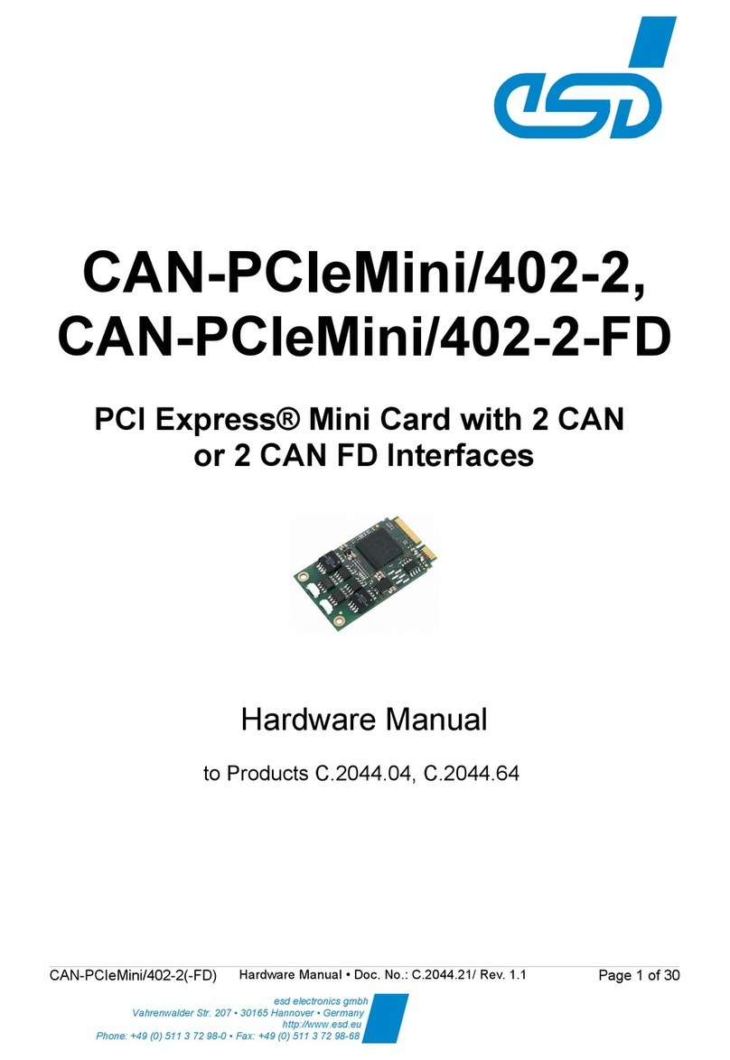
ESD CAN-PCI/402 User manual

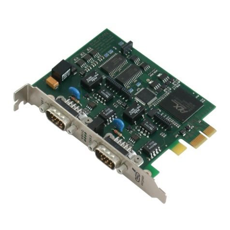
CAN-PCI/402
1, 2 or 4 Channel PCI-CAN Interface
(Layer 2, CANopen®, J1939 or A INC825)
or 2 Channel PCI-CAN FD Interface
CAN-PCI/402-2
(C.2049.04)
Hardware Manual
to Product C.2049.02 - C.2049.07,
C.2045.10, C.2045.11,
C.2049.32,
C.2049.64
CAN-PCI 402 Hardware Manual • Doc. No.: C.2049.21 Rev. 1.5 Page 1 of 43
esd electronics gmbh
Vahren alder Str. 207 • 30165 Hannover • Germany
http:// .esd.eu
Phone: +49 (0) 511 3 72 98-0 • Fax: +49 (0) 511 3 72 98-68

N O T E
The information in this document has been carefully checked and is believed to be entirely reliable.
esd electronics makes no warranty of any kind with regard to the material in this document, and
assumes no responsibility for any errors that may appear in this document. In particular
descriptions and technical data specified in this document may not be constituted to be guaranteed
product features in any legal sense.
esd electronics reserves the right to make changes without notice to this, or any of its products, to
improve reliability, performance or design.
All rights to this documentation are reserved by esd electronics. Distribution to third parties, and
reproduction of this document in any form, whole or in part, are subject to esd electronics's
written approval.
© 2021 esd electronics gmbh, Hannover
esd electronics gmbh
Vahrenwalder Str. 207
30165 Hannover
Germany
Phone: +49-511-372 98-0
Fax: +49-511-372 98-68
E-Mail: [email protected]
Internet: www.esd.eu
This manual contains important information and instructions on safe and efficient
handling of the CAN-PCI 402. Carefully read this manual before commencing any work
and follow the instructions.
The manual is a product component, please retain it for future use.
Trademark Notices
CANopen® and CiA® are registered community trademarks of CAN in Automation e.V.
Windows® is a registered trademark of Microsoft Corporation in the United States and other countries.
Linux® is the registered trademark of Linus Torvalds in the U.S. and other countries.
The PICMG® name and logo are registered trademarks of the PCI Industrial Computer Manufacturers Group.
Altera® and Intel® are trademarks of Intel Corporation or its subsidiaries in the U.S. and or other countries.
All other trademarks, product names, company names or company logos used in this manual are reserved by their
respective owners.
Page 2 of 43 Hardware Manual • Doc. No.: C.2049.21 Rev. 1.5 CAN-PCI 402

Document file: I:\Texte\Doku\MANUALS\CAN\PCI\CAN-PCI402\Englisch\CAN-PCI402_Hardware-Manual_en_15.odt
Date of print: 2021-12-23
Document type
number: DOC0800
Hardware
version:
1.3
Note to CAN FD:
For the CAN FD versions the transceiver for the increased CAN FD bit rate (up to
8 Mbit s, formerly 5 Mbit s ) is only equipped from the batch number as described in
the following table:
Product Order No. Increased bit rate available from batch number
CAN-PCI 402-2-FD C.2049.64 GJ (see chapter “Product Label ” on page 16)
Document History
The changes in the document listed below affect changes in the hardware as well as changes in
the description of the facts, only.
ev. Chapter Changes versus previous version Date
1.0 First English Hardware Manual 2015-11-10
1.1
- Safety instructions and Warning Messages revised and Classification inserted
2016-11-23
2.1, 2.2 Figure 3 and 4 new
3.2 Chapter “MSI” Jumper deleted
6.3 Description of Jumper deleted
6.5 Description of CAN Tools inserted
1.2
- Description of CAN-PCI 402-2-FD inserted
2018-05-29
1. Chapter restructured, new subsections: ”About this Manual”, “Overview of
available Hardware Versions” and “Description”
2.2 New chapter: CAN-PCI 402-1
3. Figure inserted, notes revised
6.4 New chapter ”CAN FD Interface (CAN-PCI 402-2-FD only)”
6.6 Chapter “Software Support” revised
10. CAN FD version inserted in Application Note,
11. CE-Declaration of Conformity updated
12 Chapter revised
1.3
1.3 Chapter revised, note on CAN FD added.
2019-04-25
1.3.3,
6.5
Note on potential interoperability revised
10. Chapter “Application Note to CAN 402 Boards” revised and subsection for
Linux OS added.
11. Declaration of Conformity updated
1.4 1.3, 6.4 CAN FD Bitrate of CAN-PCI 402-2-FD is 8Mbit s 2021-04-15
1.5
-For CAN-PCI 402-2-FD the increased CAN FD bit rate (up to 8 Mbit s) is only
ensured from the batch number as specified under hardware version above.
2021-12-23
2.4 New chapter: Product Label
6.4 Note on extended bit rate added
Technical details are subject to change without further notice.
CAN-PCI 402 Hardware Manual • Doc. No.: C.2049.21 Rev. 1.5 Page 3 of 43

Classification of Warning Messages and Safety Instructions
This manual contains noticeable descriptions, warning messages and safety instructions, which
you must follow to avoid personal injuries or death and property damage.
This is the safety alert symbol.
It is used to alert you to potential personal injury hazards. Obey all safety messages
and instructions that follow this symbol to avoid possible injury or death.
DANGE , WA NING, CAUTION
Depending on the hazard level the signal words DANGER, WARNING or CAUTION are used to
highlight safety instructions and warning messages. These messages may also include a warning
relating to property damage.
DANGE
Danger statements indicate a hazardous situation which, if not avoided, will result in
death or serious injury.
WA NING
Warning statements indicate a hazardous situation that, if not avoided, could result in
death or serious injury.
CAUTION
Caution statements indicate a hazardous situation that, if not avoided, could result in
minor or moderate injury.
NOTICE
Notice statements are used to notify people on hazards that could result in things other than
personal injury, like property damage.
NOTICE
This NOTICE statement indicates that the device contains components sensitive to
electrostatic discharge.
NOTICE
This NOTICE statement contains the general mandatory sign and gives information that
must be heeded and complied with for a safe use.
INFO MATION
INFO MATION
Notes to point out something important or useful.
Page 4 of 43 Hardware Manual • Doc. No.: C.2049.21 Rev. 1.5 CAN-PCI 402

Safety Instructions
● When working with the CAN-PCI 402 follow the instructions below and read the manual
carefully to protect yourself from injury and the CAN-PCI 402 from damage.
● The device is a built-in component. It is essential to ensure that the device is mounted in a way
that cannot lead to endangering or injury of persons or damage to objects.
● Do not use damaged or defective cables to connect the CAN-PCI 402 and follow the CAN wiring
hints in chapter: "Correct Wiring of Electrically Isolated CAN Networks".
● In case of damages to the device, which might affect safety, appropriate and immediate
measures must be taken, that exclude an endangerment of persons and domestic animals and
property.
● Current circuits which are connected to the device have to be sufficiently protected against
hazardous voltage (SELV according to EN 60950-1).
● The CAN-PCI 402 may only be driven by power supply current circuits, that are contact
protected. A power supply, that provides a safety extra-low voltage (SELV) according to EN
60950-1, complies with this conditions.
● The device has to be securely installed in the control cabinet before commissioning.
● Protect the CAN-PCI 402 from dust, moisture and steam.
● Protect the CAN-PCI 402 from shocks and vibrations.
● The CAN-PCI 402 may become warm during normal use. Always allow adequate ventilation
around the CAN-PCI 402 and use care when handling.
● Do not operate the CAN-PCI 402 adjacent to heat sources and do not expose it to unnecessary
thermal radiation. Ensure an ambient temperature as specified in the technical data.
DANGE
Hazardous Voltage - isk of electric shock due to unintentional contact with
uninsulated live parts with high voltages inside of the system into which the CAN-PCI 402
is to be integrated.
→ Disconnect all hazardous voltages (mains voltage) before opening the system.
→ Ensure the absence of voltage before starting any electrical work
NOTICE
Electrostatic discharges may cause damage to electronic components.
→
→
To avoid this, please discharge the static electricity from your body before you touch
the CAN-PCI 402.
Furthermore, you should prevent your clothes from touching the CAN-PCI 402,
because your clothes might be electrostatically charged as well.
Qualified Personnel
This documentation is directed exclusively towards personnel qualified in control and automation
engineering.
The installation and commissioning of the product may only be carried out by qualified personnel,
which is authorized to put devices, systems and electric circuits into operation according to the
applicable national standards of safety engineering.
Conformity
The CAN-PCI 402 is an industrial product and meets the demands of the EU regulations and EMC
standards printed in the conformity declaration at the end of this manual.
Warning: In a residential, commercial or light industrial environment the CAN-PCI 402 may cause
radio interferences in which case the user may be required to take adequate measures.
The CAN-PCI 402 is a sub-assembly intended for incorporation into an apparatus by a manufacturer.
The manufacturer of the final system must decide, whether additional EMC or EMI protection
requirements are necessary.
CAN-PCI 402 Hardware Manual • Doc. No.: C.2049.21 Rev. 1.5 Page 5 of 43

Intended Use
The intended use of the CAN-PCI 402 is the operation as PCI-CAN interface board.
The guarantee given by esd does not cover damages which result from improper use, usage not in
accordance with regulations or disregard of safety instructions and warnings.
●The CAN-PCI 402 is intended for installation in a PCI system only.
●The operation of the CAN-PCI 402 in hazardous areas, or areas exposed to potentially explosive
materials is not permitted.
●The operation of the CAN-PCI 402 for medical purposes is prohibited.
Service Note
The CAN-PCI 402 does not contain any parts that require maintenance by the user. The CAN-
PCI 402 does not require any manual configuration of the hardware except the configuration of the
jumpers as described in chapter “Jumper Configuration”. Unauthorized intervention in the device
voids warranty claims.
Disposal
Devices which have become defective in the long run have to be disposed in an appropriate way or
have to be returned to the manufacturer for proper disposal. Please, make a contribution to
environmental protection.
Typographical Conventions
Throughout this manual the following typographical conventions are used to distinguish technical terms.
Convention Example
File and path names /dev/null or <stdio.h>
Function names open()
Programming constants NULL
Programming data types uint32_t
Variable names Count
Number epresentation
All numbers in this document are base 10 unless designated otherwise. Hexadecimal numbers have a
prefix of 0x, and binary numbers have a prefix of 0b. For example, 42 is represented as 0x2A in
hexadecimal and 0b101010 in binary.
Abbreviations
API Application Programming Interface
CAN Controller Area Network
CPU Central Processing Unit
CiA CAN in Automation
HW Hardware
I O Input Output
LSB Least Significant Bit
MSB Most Significant Bit
n.a. not applicable
OS Operating System
SDK Software Development Kit
Page 6 of 43 Hardware Manual • Doc. No.: C.2049.21 Rev. 1.5 CAN-PCI 402

Table of contents
Safety Instructions...........................................................................................................................5
1. Overview......................................................................................................................................9
1.1 About this Manual..................................................................................................................9
1.2 Overview of available Hardware Versions..............................................................................9
1.3 Description...........................................................................................................................11
1.3.1 Classical CAN..............................................................................................................11
1.3.2 CAN FD.......................................................................................................................11
1.3.3 General Properties......................................................................................................12
1.3.4 Customized Options....................................................................................................13
2. PCB View with Connectors and Jumpers...................................................................................14
2.1 CAN-PCI 402-2(-FD)............................................................................................................14
2.2 CAN-PCI 402-1....................................................................................................................14
2.3 CAN-PCI 402-4 2-Slot View.................................................................................................15
3. Jumper Configuration.................................................................................................................16
3.1 CAN Termination .................................................................................................................16
4. Hardware Installation..................................................................................................................17
5. Front Panel View with LED-Display............................................................................................19
5.1 CAN-PCI 402-2(-FD) LEDs..................................................................................................19
5.2 Additional LEDs on CAN-PCIe 402-Slot2 Adapter Board.....................................................20
6. Technical Data............................................................................................................................21
6.1 General Technical Data........................................................................................................21
6.2 PCI Interface........................................................................................................................21
6.3 Classical CAN Interfaces ....................................................................................................22
6.4 CAN FD Interface (CAN-PCI 402-2-FD only).......................................................................22
6.5 Message-Signalled Interrupt Handling.................................................................................23
6.6 Software Support.................................................................................................................23
6.6.1 CAN-PCI 402 Classical CAN Versions........................................................................23
6.6.2 CAN-PCI 402-2-FD ....................................................................................................23
6.6.3 CAN Tools...................................................................................................................24
7. Connector Assignments..............................................................................................................25
7.1 CAN.....................................................................................................................................25
8. Correct Wiring of Electrically Isolated CAN Networks.................................................................26
8.1 Standards concerning CAN Wiring......................................................................................26
8.2 Light Industrial Environment (Single Twisted Pair Cable).....................................................27
8.2.1 General Rules.............................................................................................................27
8.2.2 Cabling........................................................................................................................28
8.2.3 Branching....................................................................................................................28
8.2.4 Termination..................................................................................................................28
8.3 Heavy Industrial Environment (Double Twisted Pair Cable).................................................29
8.3.1 General Rules.............................................................................................................29
8.3.2 Device Cabling............................................................................................................30
8.3.3 Branching....................................................................................................................30
8.3.4 Termination..................................................................................................................30
8.4 Electrical Grounding.............................................................................................................31
8.5 Bus Length...........................................................................................................................31
8.6 Examples for CAN Cables...................................................................................................32
8.6.1 Cable for light industrial Environment Applications (Two-Wire)....................................32
8.6.2 Cable for heavy industrial Environment Applications (Four-Wire)................................32
9. CAN Troubleshooting Guide.......................................................................................................33
9.1 Termination..........................................................................................................................33
CAN-PCI 402 Hardware Manual • Doc. No.: C.2049.21 Rev. 1.5 Page 7 of 43

9.2 Electrical Grounding.............................................................................................................34
9.3 Short Circuit in CAN Wiring..................................................................................................34
9.4 CAN_H CAN_L-Voltage ......................................................................................................34
9.5 CAN Transceiver Resistance Test........................................................................................35
9.6 Support by esd.....................................................................................................................35
10. Application Note to CAN 402 Boards........................................................................................36
10.1 Windows Operating System...............................................................................................36
10.2 Linux Operating System.....................................................................................................37
11. Declaration of Conformity.........................................................................................................39
12. Order Information.....................................................................................................................40
12.1 Hardware...........................................................................................................................40
12.2 Software.............................................................................................................................41
12.2.1 Classical CAN...........................................................................................................41
12.2.2 CAN FD.....................................................................................................................42
12.3 PDF Manuals.....................................................................................................................42
Page 8 of 43 Hardware Manual • Doc. No.: C.2049.21 Rev. 1.5 CAN-PCI 402

Overview
1. Overview
1.1 About this Manual
In this hardware manual all versions of the CAN-PCI 402 are described together as CAN-PCI 402.
Differences of the CAN-PCI 402 variants are noted accordingly.
Available features, options and supplied items may vary depending on the CAN-PCI 402 version
you selected.
1.2 Overview of available Hardware Versions
2x CAN Version - Standard version
CAN-PCI/402-2
2 CAN interfaces,
2x DSUB9,
electrical isolation
(C.2049.04)
CAN-PCI/402-2-D
2 CAN interfaces,
2x DSUB9,
without electrical
isolation
(C.2049.05)
CAN-PCI/402-2-FD
2 CAN FD interfaces,
2x DSUB9,
electrical isolation
(C.2049.64)
1x CAN Version
CAN-PCI/402-1
1 CAN interface,
1x DSUB9,
electrical isolation
(C.2049.02)
CAN-PCI/402-1-D
1 CAN interface,
1x DSUB9,
without electrical
isolation
(C.2049.03)
CAN-PCI 402 Hardware Manual • Doc. No.: C.2049.21 Rev. 1.5 Page 9 of 43

Overview
4x CAN with Adapter Board
CAN-PCIe/402-Slot2
Adapter Board with
2 CAN interfaces,
2x DSUB9,
electrical isolation
(C.2045.10)
includes ribbon cable
CAN-PCIe/402-Slot2-D
Adapter Board with
2 CAN interfaces,
2x DSUB9,
without electrical isolation,
(C.2045.11)
includes ribbon cable
CAN-PCI/402-4/2Slot
4 CAN interfaces
with electrical isolation
(C.2049.06)
includes C.2049.04
and adapter board
C.2045.10
CAN-PCI/402-4/2Slot-D
4 CAN interfaces
without electrical isolation
(C.2049.07)
includes C.2049.05
and adapter board
C.2045.11
Low Profile Version Option on equest only
CAN-PCI/402-1-LP
1 CAN interface,
1x DSUB9,
electrical isolation
(C.2049.32)
CAN-PCI/402-1-
LP-2
Extension board
1 CAN interface,
1x DSUB9,
electrical isolation
(C.2049.34),
cable included
4x CAN, DSUB37-Version Option on equest only Accessories
CAN-PCI/402-B4/1 Slot
4 CAN interfaces,
1x DSUB37,
electrical isolation
(C.2049.08)
CAN-PCI/4xx-B4-1C4
DSUB37-to-4xDSUB9
CAN Adapter Cable
DSUB37 to 4x DSUB9
(C.2041.18)
Page 10 of 43 Hardware Manual • Doc. No.: C.2049.21 Rev. 1.5 CAN-PCI 402

Overview
1.3 Description
1.3.1 Classical CAN
Figure 1: Block circuit diagram of Classical CAN versions
The CAN-PCI 402 is a PC board designed for the PCI bus that features one, two (CAN-PCI 402-2)
or four (CAN-PCI 402-4 2Slot) electrically isolated high-speed CAN interfaces according to ISO
11898-2. The Classical CAN versions support CAN bit rates up to 1 Mbit s. The independent CAN
interfaces are designed according to ISO 11898-1.
The CAN-PCI 402-4 2Slot comes with the standard version CAN-PCI 402-2 and an adapter board
(CAN-PCIe 402-Slot2) with two additional CAN interfaces.
These product versions are also available without electrical isolation.
Equipped with up to two CAN interfaces the board is available as low profile version CAN-PCI 402-
1-LP (optional CAN-PCI 402-LP-2 on request).
1.3.2 CAN FD
Figure 2: Block circuit diagram of CAN-PCI 402-2-FD
In the CAN FD version CAN-PCI 402-2-FD the board comes with two electrically isolated CAN FD
interfaces. The CAN-PCI 402-2-FD supports CAN bit rates from 10 kbit s up to 8 Mbit s. The
independent CAN FD interfaces are designed according to ISO 11898-1:2015.
CAN FD
Due to the higher bit rate in the data phase in combination with the increase of efficiency by a
higher number of user-data bytes, CAN FD offers a higher data throughput while maintaining the
qualities of the Classical CAN.
CAN-PCI 402 Hardware Manual • Doc. No.: C.2049.21 Rev. 1.5 Page 11 of 43
C
A
N
B
U
S
Physical
CAN
Layer
CAN0
CAN1
DSUB9
CiA pinning
DC/DC
Converter
Electrical Isolation
PCI
Card Edge
Connector
2
CAN Core
with
Timestamp
FPGA
Altera EP4CGX
CAN
CAN
PCI to PCIe
Bridge
CAN2
CAN3
CAN0
CAN1
DSUB9
CiA pinning
Standard Version CAN-PCI/402-2 (electrical isolation optional)
Optional
Electrical
Isolation
PCI
Card Edge
Connector
4
CAN Core
with
Timestamp
FPGA
Altera EP4CGX
C
A
N
B
U
S
DSUB9
CiA pinning
C
A
N
B
U
S
Optional
Electrical
Isolation
PCI to PCIe
Bridge
Adapter Board CAN-PCI/402-Slot2 (electrical isolation optional)
10-pin
post connector
CAN-adapter board
Ribbon
Cable

Overview
The CAN FD version CAN-PCI 402-2-FD is fully backwards compatible with CAN and can also be
used in Classical CAN applications.
INFO MATION
Every CAN FD controller is backward compatible to the Classical CAN protocol.
Classical CAN nodes and CAN FD nodes can communicate with each other as long as
the CAN FD frame format remains unused!
You can insert for example the CAN FD version CAN-PCI 402-2-FD in your Classical CAN
application if you want to replace a Classical CAN component. The CAN FD board automatically
communicates like a Classical CAN board (the existing program code can be used unchanged).
The CAN-PCI 402-2-FD has to communicate with the CAN nodes via Classical CAN frames,
because Classical CAN controllers do not tolerate CAN FD frames. All controllers have to use the
same Classical CAN Bitrate.
INFO MATION
During the initialisation of the CAN controller of the CAN FD boards the application
determines via software if the CAN FD boards communicate with Classical CAN or with
CAN FD.
See NTCAN-API Manual Part 1: “Application Developers Manual” for further information.
NOTICE
The system integrator has to verify that all CAN nodes on the bus are set to the same bit
rate!
If you work with a Classical CAN application and want to migrate to CAN FD in the future, you can
replace your Classical CAN nodes one after another until all CAN nodes are replaced by CAN FD
nodes.
1.3.3 General Properties
esdACC
The CAN or CAN FD interfaces are driven by the ISO 16845:2004 certified esdACC (esd advanced
CAN Core) implemented in an Intel® (formerly Altera®) FPGA.
For further information about esdACC see https: esd.eu en products esdacc.
CAN Data Management
The FPGA supports bus mastering (first-party DMA) to transfer data to the host memory. This
results in a reduction of the overall latency on servicing I O transactions in particular at higher data
rates and a reduced host CPU load.
Due to the usage of MSI (Message Signalled Interrupts) the CAN-PCI 402 can be operated for
example in Hypervisor environments.
The CAN-PCI 402 provides 64-bit high resolution hardware timestamp with bit time accuracy.
Software
The CAN layer 2 (NTCAN-API) drivers for Windows® and Linux® are included in the scope of
delivery. Additional CAN layer 2 (NTCAN-API) drivers for real-time operating systems (QNX®, RTX,
RTX64, VxWorks® and On Time RTOS-32) and the higher-layer protocol stacks (CANopen®,
J1939, ARINC825) can be ordered separately. See chapter “Software Support” on page 24 for
further information.
Additional free-of-charge esd CAN tools for Windows are downloadable from our website. The
tools offer efficient setup and analysis of Classical CAN applications and networks.
Page 12 of 43 Hardware Manual • Doc. No.: C.2049.21 Rev. 1.5 CAN-PCI 402

Overview
NOTICE
CAN-PCI 402 boards which are equipped with the Pericom® PCI-to-PCI bridge
PI7C9X111SL might have a potential interoperability problem in Microsoft Windows and
Linux operating systems. Please read chapter “Application Note to CAN 402 Boards“ on
page 37 for further information.
1.3.4 Customized Options
Customized options are available for customized series production in reasonable quantities.
Please contact our sales team for detailed information.
Customized options are for example:
• Extended temperature range: -40° C … +75° C
• Low profile version with CAN FD interface
• Error simulation support
• PCI board with 4 CAN (FD) interfaces via 1x DSUB37 connector in the front panel
CAN-PCI 402 Hardware Manual • Doc. No.: C.2049.21 Rev. 1.5 Page 13 of 43

PCB View with Connectors and Jumpers
2. PCB View with Connectors and Jumpers
2.1 CAN-PCI/402-2(-FD)
Figure 3: CAN-PCI 402-2 PCB top view
See also page 26 for signal assignment of the CAN connectors.
The figure above shows the module in the 2-channel standard version CAN-PCI 402-2. The figure
applies accordingly for the CAN FD version CAN-PCI 402-2-FD. Please refer to order information
on page 41 for an overview of the available hardware designs.
2.2 CAN-PCI/402-1
In the CAN-PCI 402-1 versions the CAN interface CAN 1 (see Figure 3) is not equipped. See also
chapter “Overview of available Hardware Versions” on page 9 for further information.
Page 14 of 43 Hardware Manual • Doc. No.: C.2049.21 Rev. 1.5 CAN-PCI 402

PCB View with Connectors and Jumpers
2.3 CAN-PCI/402-4/2-Slot View
Figure 4: CAN-PCI 402-4 2Slot
The figure 4 above shows the module in the four CAN version CAN-PCI 402-4 2Slot. It consists of
the standard version CAN-PCI 402-2 and the additional adapter board CAN-PCIe 402-Slot2 (see
figure 5 below).
Figure 5: CAN-PCIe 402-Slot2 Adapter View
CAN-PCI 402 Hardware Manual • Doc. No.: C.2049.21 Rev. 1.5 Page 15 of 43

PCB View with Connectors and Jumpers
2.4 Product Label
esd Product label
example
The esd product label is placed
on the PCB and shows: Example:
- CE label
- esd logo
- esd order number (PN:)
- Batch and serial number (SN:)
- Product name
- Data matrix code
- Field for quality assurance (T)
C.2049.64
Batch: GH, Serial no.: 000432
CAN-PCI 402-2-FD
Figure 6: Example of product label (order of the items may deviate)
Page 16 of 43 Hardware Manual • Doc. No.: C.2049.21 Rev. 1.5 CAN-PCI 402

Jumper Configuration
3. Jumper Configuration
3.1 CAN Termination
An on-board termination resistor of 120Ω can be individually enabled for each CAN interface via
jumpers.
For the position of the jumpers and jumper depots of CAN0 and CAN1 on CAN-PCI 402-2(-FD)
see Figure 3 on page 14.
For the position of the jumpers and jumper depots of CAN2 and CAN3 on the adapter board CAN-
PCIe 402-Slot2 see Figure 5 on page 15.
Jumper Jumper set Jumper not set Jumper
Depot
JP610 internal termination of CAN1 CAN1 has to be terminated externally JP531
JP600 internal termination of CAN0 CAN0 has to be terminated externally JP530
The following jumpers are only equipped on the adapter board CAN-PCIe 402-2Slot:
JP410 internal termination of CAN3 CAN3 has to be terminated externally JP441
JP400 internal termination of CAN2 CAN2 has to be terminated externally JP440
NOTICE
If a jumper is not set on the jumper depot, the corresponding CAN interface will be
interpreted as internally terminated.
Therefore it is strongly recommended to keep the jumpers which are not needed for
CAN termination on the corresponding jumper depots CAN0 - CAN3!
Figure 7: Positions of the Jumper Depots CAN0 and CAN1 or CAN2 and CAN3
CAN-PCI 402 Hardware Manual • Doc. No.: C.2049.21 Rev. 1.5 Page 17 of 43

Hardware Installation
4. Hardware Installation
NOTICE
ead the safety instructions at the beginning of this document carefully, before
you start with the hardware installation!
DANGE
Hazardous Voltage - isk of electric shock due to unintentional contact with
uninsulated live parts with high voltages inside of the system into which the CAN-PCI 402
is to be integrated.
→ Disconnect all hazardous voltages (mains voltage) before opening the system.
→ Ensure the absence of voltage before starting any electrical work
NOTICE
Electrostatic discharges may cause damage to electronic components.
→
→
To avoid this, please discharge the static electricity from your body by touching the
metal case of the PCI system before you touch the CAN-PCI 402.
Furthermore, you should prevent your clothes from touching the CAN-PCI 402,
because your clothes might be electrostatically charged as well.
Procedure:
1. Switch off your system and all connected peripheral devices (monitor, printer, etc.). Switch off
the connected CAN devices.
2. Discharge your body as described above.
3. Disconnect the power supply of the PC from the mains.
DANGE
Hazardous Voltage - Risk of electric shock due to unintentional contact with
uninsulated live parts with high voltages inside of the system into which the CAN-
PCI 402 is to be integrated.
→
→
→
→
Disconnect all hazardous voltages (mains voltage) before opening the system.
If the system does not have a flexible mains cable, but is directly connected to
mains, disconnect the power supply via the safety fuse and make sure that the
fuse cannot switch on again unintentionally (i.e. with caution label).
Ensure the absence of voltage before starting any electrical work
Cover or block off adjacent live parts.
4. Open the case.
5. Set the jumpers for the internal termination of the CAN (FD) interfaces according to your
needs (see page 17).
Make sure that the jumpers of the CAN interfaces which are not internally terminated are
kept on the corresponding depots.
6. Select an open PCI slot and remove the slot cover at the back of the PC.
The CAN module can be inserted into every PCI slot.
7. Insert the CAN-PCI 402 board into the selected PCI slot. Carefully push the board down until
it snaps into place.
8. Attach the CAN-PCI 402 board.
Page 18 of 43 Hardware Manual • Doc. No.: C.2049.21 Rev. 1.5 CAN-PCI 402

Hardware Installation
9. If you are installing the CAN-PCI 402-4 2Slot module with 4 CAN interfaces you have to
install the adapter board CAN-PCIe 402-Slot2 in the PCI slot next to the CAN-PCI 402-2
board. Connect the two boards with the included ribbon cable (see figure 4 on page 15) via
the 10-pin post connectors on the bard and on the adapter.
10. Close the system's case again.
11. Connect the CAN wire.
NOTICE
Please note that the CAN bus has to be terminated at both ends!
CAN-PCI/402-2(-FD):
The first CAN interface (CAN0) has to be connected via the lower DSUB connector (X600)
and the second CAN interface (CAN1) has to be connected via the upper DSUB connector
(X610). You will find a figure showing the connectors on page 14.
CAN-PCI/402-4/2Slot:
If you are installing a CAN-PCI 402-4 2Slot with adapter board, you have to connect the third
CAN interface (CAN2) via the lower DSUB connector (X400) of the adapter board and the
fourth CAN interface (CAN3) via the upper DSUB connector (X410) of the adapter board (see
figure 5, page 15).
efer to order information on page 41 to verify your hardware configuration.
For CAN-PCI/402 boards with electrical isolation:
If the integrated CAN termination of the CAN interface is not set via the jumpers, the interface
has to be terminated externally, read chapter “Correct Wiring of Electrically Isolated CAN
Networks“, from page 27.
For external termination esd offers suitable termination connectors for the CAN bus.
Additionally the CAN_GND signal has to be connected to earth at exactly one point.
A CAN participant with electrical connection to earth potential acts as an earth connection.
For CAN-PCI/402 boards without electrical isolation:
In order to avoid that possible lightning currents are discharged via the motherboard and thus
to avoid damage, CAN_GND is internally connected to the front panel and thus to earth
potential.
This does not supersede the external connection to earth potential!
NOTICE
Make sure that an external connection to the same earth potential is installed as near
as possible to the connector in the front panel before you go on with the installation.
Together with the internal earth connection this acts as a single earthing point.
12. Connect the system to mains again (mains connector or fuse).
13. Switch on the system and the peripheral devices.
14. End of hardware installation.
Continue with the software installation as described in the manual ‘NTCAN-API, Installation
Guide’.
CAN-PCI 402 Hardware Manual • Doc. No.: C.2049.21 Rev. 1.5 Page 19 of 43

Front Panel View with LED-Display
5. Front Panel View with LED-Display
5.1 CAN-PCI/402-2(-FD) LEDs
The CAN-PCI 402-2 standard version and the CAN FD version CAN-PCI 402-2-FD are equipped
with four green LEDs in the front panel.
Figure 8: Front panel view of CAN-PCI 402-2(-FD)
Label Name Indicator
State Description
LED name
in schematic
diagram
ATraffic
CAN0
off no CAN bus connection and or no CAN traffic on CAN0 D520A
on connected to CAN bus 0 and CAN traffic on CAN0
BTraffic
CAN1
off no CAN bus connection and or no CAN traffic on CAN1 D520B
on connected to CAN bus 1 and CAN traffic on CAN1
Creserved - - D520C
DPower off power supply voltage off D520D
on power supply voltage on
Table 1: LEDs
Page 20 of 43 Hardware Manual • Doc. No.: C.2049.21 Rev. 1.5 CAN-PCI 402
Other manuals for CAN-PCI/402
1
This manual suits for next models
6
Table of contents
Other ESD Computer Hardware manuals

ESD
ESD CAN-PCIeMini/402-2 User manual

ESD
ESD CPCI-DP-2S User manual

ESD
ESD CPCI-405 User manual

ESD
ESD VME-DIO32-C User manual

ESD
ESD CPCI-ASIO4 User manual

ESD
ESD VME-DIO32-L User manual

ESD
ESD PMC-CPU/440 User manual

ESD
ESD CAN-PCIe/200 User manual

ESD
ESD PMC-CAN/402-4-FD User manual

ESD
ESD XMC-CPU/T10 User manual