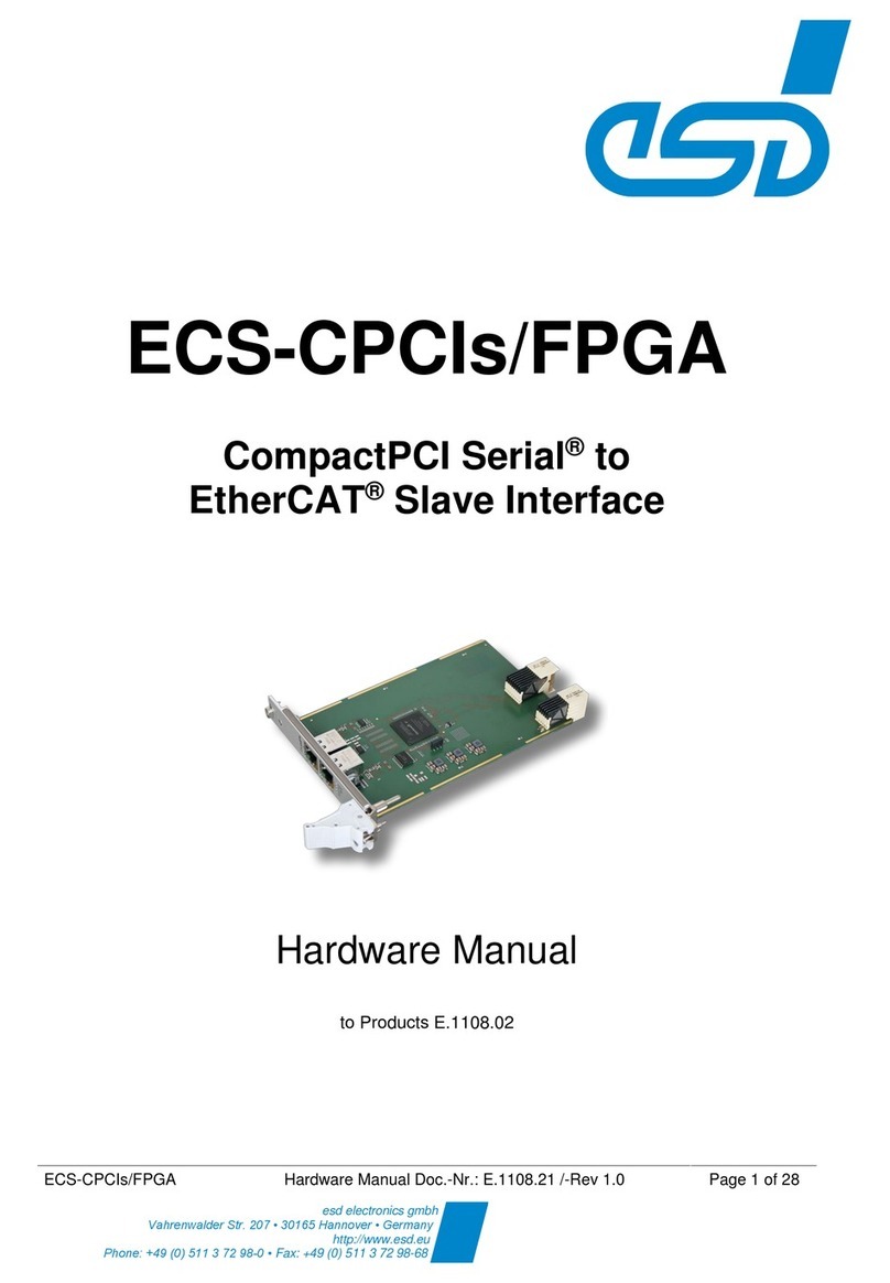
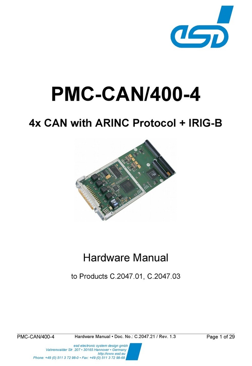
ESD PMC-CPU/440 User manual

PMC-CPU/440
Status: released
PMC-CPU/440
PowerPC 440EPx PrPMC module
__________
User Manual
Product Order No. V.2027.02 05
User Manual V.2027.21
Filename: PMC
CPU440_Manual_en_13.odt
Revision 1.3
2012 06 11
All rights reserved.
Copyright © esd gmbh 2012
Page
1 of 49

PMC-CPU/440
Status: released
N O T E
The information in this document has been carefully checked and is believed to be entirely reliable.
esd makes no warranty of any kind with regard to the material in this document, and assumes no
responsibility for any errors that may appear in this document. In particular descriptions and technical
data specified in this document may not be constituted to be guaranteed product features in any legal
sense.
esd reserves the right to make changes without notice to this, or any of its products, to improve
reliability, performance or design.
All rights to this documentation are reserved by esd. Distribution to third parties, and reproduction of
this document in any form, whole or in part, are subject to esd's written approval.
© 2012 esd electronic system design gmbh, Hannover
esd electronic system design gmbh
Vahrenwalder Str. 207
30165 Hannover
Germany
Phone: +49 511 372 98 0
Fax: +49 511 372 98 68
Internet: www.esd.eu
Trademark Notices
All trademarks, product names, company names or company logos used in this manual are reserved by their respective
owners.
User Manual V.2027.21
Filename: PMC
CPU440_Manual_en_13.odt
Revision 1.3
2012 06 11
All rights reserved.
Copyright © esd gmbh 2012 Page
2 of 49

PMC-CPU/440
Status: released
Document Information
document no.: V.2027.21
document type: DOC08xx
document status: released
document revision: 1.3
date of creation: 2012 06 11
document path: I:\Texte\Doku\MANUALS\PMC\PMC CPU440\
document filename: PMC CPU440_Manual_en_13.odt
number of pages / annex: 49 / 0
Responsi le for content / author
Name Company /
Department
Phone Email
Distri ution / Review
Name Firma / A teilung Telefon Email
User Manual V.2027.21
Filename: PMC
CPU440_Manual_en_13.odt
Revision 1.3
2012 06 11
All rights reserved.
Copyright © esd gmbh 2012 Page
3 of 49

PMC-CPU/440
Status: released
Modification history
Technical modifications in this overview are marked by an additional "!".
The following overview is handled from revision 1.0.
! Revision Chapter Page Changelog Date / Sign
0.9 all all Document created 2008 03 18 / MF
1.0 all all Initial release 2008 03 28 / MF
10.5.3 27 Added 'sbe' command describtion 2008 04 01 / MF
8.2 22 Added chapter 2008 04 09 / MF
10.5.5 28 Chapter rewritten
13 49 Added Appendix (GPL License) 2008 05 09 / MF
1.1 11.2
11.6 33 Chapters added 2008 07 04 / MF
!9, 7 22, 20 Added hardware reset capability via memory
access, shrinked BAR2 from 16MB to 4MB 2008 09 12 / MF
13 49 Add reference to 3rd party lisensor document 2008 10 31 / MF
1.2 div. div. Minor corrections 2009 01 14 / MF
1.2a 1.2.1,
12 9, 48 Added EMC notice and EC Declation of
Conformity 2012 05 24 / MF
!1.1, 18 8, 6.3.1 Added „ext. IO Variant (V.2027.05) 2012 05 24 / MF
12 48 Updated ordering information 2012 05 24 / MF
Deleted empty chapter 5 (GPIO Functions)
Deleted full GPL license code from appendix.
The license text is provided in a separate
document (see chapter 10.1).
2012 05 24 / MF
!11.2
11.4 33 42
Updated FPGA register description based on
FPGA design version 0x0e
added interrupt capability to IRIG B function
(see IRIG_CTRL, HOSTCTRL and STATUS
registers)
added timestamp reset via IRIG B control flag
feature (see TSCTRL register)
added DDFSDBG register
2012 05 24 / MF
1.2b
Safety Instructions inserted
2012 06 05 /AV12, 13 48,49 Chapter order exchanged, chapter: "Appendix"
renamed to "Declaration of Conformity"
10.1 23 Note to appendix removed
1.3 Editorial revision 2012 06 11 /AV
User Manual V.2027.21
Filename: PMC
CPU440_Manual_en_13.odt
Revision 1.3
2012 06 11
All rights reserved.
Copyright © esd gmbh 2012 Page
4 of 49

PMC-CPU/440
Status: released
Safety Instructions
!When working with PMC CPU/440 follow the instructions below and read the manual carefully to protect yourself from
injury and the PMC CPU/440 from damage.
!The device is a built in component. It is essential to ensure that the device is mounted in a way that cannot lead to
endangering or injury of persons or damage to objects.
!The device has to be securely installed in the control cabinet before commissioning.
!Protect the PMC CPU/440 from dust, moisture and steam.
!Protect the PMC CPU/440 from shocks and vibrations.
!The PMC CPU/440 may become warm during normal use. Always allow adequate ventilation around the PMC CPU/440
and use care when handling.
!Do not operate the PMC CPU/440 adjacent to heat sources and do not expose it to unnecessary thermal radiation.
Ensure an ambient temperature as specified in the technical data.
!Do not use damaged or defective cables to connect the PMC CPU/440.
!In case of damages to the device, which might affect safety, appropriate and immediate measures must be taken, that
exclude an endangerment of persons and objects.
!Current circuits which are connected to the device have to be sufficiently protected against hazardous voltage (SELV
according to EN 60950 1).
!The PMC CPU/440 may only be driven by power supply current circuits, that are contact protected.
A power supply, that provides a safety extra low voltage (SELV or PELV) according to EN 60950 1, complies with this
conditions.
Attention !
Electrostatic discharges may cause damage to electronic components.
To avoid this, please discharge the static electricity from your body before you touch the PMC
CPU/440.
Qualified Personal
This documentation is directed exclusively towards personal qualified in control and automation engineering.
The installation and commissioning of the product may only be carried out by qualified personal, which is authorized to put
devices, systems and electric circuits into operation according to the applicable national standards of safety engineering.
Intended Use
The intended use of the PMC CPU/440 is the operation as PMC module in a PMC carrier system.
The guarantee given by esd does not cover damages which result from improper use, usage not in accordance with
regulations or disregard of safety instructions and warnings.
!The PMC CPU/440 is intended for installation in a PMC carrier system only.
!The operation of the PMC CPU/440 in hazardous areas, or areas exposed to potentially explosive materials is not
permitted.
!The operation of the PMC CPU/440 for medical purposes is prohibited.
Service Note
The PMC CPU/440 does not contain any parts that require maintenance by the user. The PMC CPU/440 does not require
any manual configuration of the hardware.
Disposal
Devices which have become defective in the long run have to be disposed in an appropriate way or have to be returned to
the manufacturer for proper disposal. Please, make a contribution to environmental protection.
User Manual V.2027.21
Filename: PMC
CPU440_Manual_en_13.odt
Revision 1.3
2012 06 11
All rights reserved.
Copyright © esd gmbh 2012 Page
5 of 49

PMC-CPU/440
Status: released
Contents
1 Overview........................................................................................................................................... 8
1.1 Description Of The PMC CPU/440 Module...............................................................................8
1.2 Technical Data..........................................................................................................................9
1.2.1 General..............................................................................................................................9
1.2.2 CPU Core..........................................................................................................................9
1.2.3 Realtime Clock (RTC)........................................................................................................9
1.2.4 PCI Interface.................................................................................................................... 10
1.2.5 Serial Interfaces............................................................................................................... 10
1.2.6 CAN Interfaces.................................................................................................................10
1.2.7 Ethernet Interfaces...........................................................................................................11
1.2.8 USB Interface (Host or Device)........................................................................................11
2 Installation Instructions....................................................................................................................11
3 Front Panel..................................................................................................................................... 11
4 Top and Bottom Side......................................................................................................................12
5 JTAG Debug Interface....................................................................................................................14
5.1 JTAG Chain Description..........................................................................................................14
5.2 JTAG Connector (X5)..............................................................................................................14
6 PMC Connectors............................................................................................................................. 16
6.1 PMC P1 Connector.................................................................................................................. 16
6.2 PMC P2 Connector.................................................................................................................. 17
6.3 PMC P4 I/O Connector............................................................................................................18
6.3.1 Pinout............................................................................................................................... 18
6.3.2 Signal Description............................................................................................................19
7 Local Memory Map......................................................................................................................... 20
8 Interrupts......................................................................................................................................... 22
8.1 External Interrupt Assignment.................................................................................................22
8.2 PCI Interrupt Handling.............................................................................................................22
8.2.1 Monarch Mode.................................................................................................................22
8.2.2 Asserting PCI Interrupts In Non monarch Mode...............................................................22
8.2.3 Asserting Local Interrupts From PCI Bus.........................................................................22
9 PCI Configuration............................................................................................................................ 22
10 Bootloader.....................................................................................................................................23
10.1 License.................................................................................................................................. 23
10.2 Configuration and Console Access........................................................................................23
10.3 Default Bootloader Environment............................................................................................24
10.4 Flash Update......................................................................................................................... 25
10.5 BSP Commands....................................................................................................................26
10.5.1 irigb Get / Set IRIG B time...........................................................................................26
10.5.2 inta – Assert / Deassert PCI interrupt line on PMC440...................................................26
10.5.3 sbe – configure CPU strapping......................................................................................27
10.5.4 fifo – Control Hardware FIFO Module............................................................................27
10.5.5 loadpci – Start PCI firmware loading..............................................................................28
10.5.6 fpga command...............................................................................................................29
10.5.7 painit Command............................................................................................................. 30
10.5.8 USB............................................................................................................................... 30
10.5.9 resetout Command........................................................................................................30
10.6 Special Environment Variables..............................................................................................31
10.6.1 pcidelay Variable............................................................................................................31
10.6.2 ptm1la, ptm1ms, ptm2la and ptm2ms Variables............................................................31
10.6.3 pram Variable.................................................................................................................31
User Manual V.2027.21
Filename: PMC
CPU440_Manual_en_13.odt
Revision 1.3
2012 06 11
All rights reserved.
Copyright © esd gmbh 2012 Page
6 of 49
PMC-CPU/440
Status: released
11 FPGA............................................................................................................................................ 32
11.1 Functional Blocks..................................................................................................................32
11.2 FPGA Registers.....................................................................................................................33
11.3 Register Description..............................................................................................................35
11.3.1 CTRL Register (0x0000)................................................................................................35
11.3.2 STATUS Register (0x0004)...........................................................................................38
11.3.3 CTRLB Register (0x0008)..............................................................................................38
11.3.4 TSCTRL Timestamp unit control register (0x0018)......................................................39
11.3.5 HOSTCTRL – Host control register (0x0060).................................................................39
11.3.6 DDFS* – Clock generator registers (0x0070 0x0078)....................................................41
11.3.7 FIFO<0...3>_DATA........................................................................................................42
11.3.8 FIFO<0...3>_CTRL........................................................................................................42
11.4 FPGA Interrupts.....................................................................................................................42
11.5 Using the FIFO module.........................................................................................................42
11.6 FPGA Custom Module...........................................................................................................46
11.6.1 Custom Module Conventions.........................................................................................47
11.6.2 Sample Custom Module „simple_io“..............................................................................47
12 EC Declaration of Conformity........................................................................................................48
13 Ordering Information..................................................................................................................... 49
User Manual V.2027.21
Filename: PMC
CPU440_Manual_en_13.odt
Revision 1.3
2012 06 11
All rights reserved.
Copyright © esd gmbh 2012 Page
7 of 49

PMC-CPU/440
1 Overview Status: released
1 Overview
1.1 Description Of The PMC-CPU/440 Module
The PMC CPU/440 is a PMC module in ‘single’ PCI Mezzanine Card form factor. It can act as PMC
monarch (PrPMC) or as non monarch (adapter/target) board. Apart from a powerful CPU core the
PowerPC 440EPx embedded processor integrates a DDR2 RAM controller, a PCI bus interface, a
controller for serial interfaces and two gigabit Ethernet MACs.
The module comes with DDR2 RAM and flash memories, a double layer capacitor buffered realtime
clock (RTC) and a FPGA. A serial console is provided through an USB device port that integrates a
USB to serial converter. This is in accordance to modern PC technologies abandoning serial ports. A
second serial interface is accessible via the PMC I/O connector with RS232 signal levels.
The module provides two 1000 BASE T gigabit Ethernet port on the front panel. Their link status and
several other status information are indicated by 5 LEDs.
The on board FPGA provides extended flexibilities for specialized applications. The default FPGA
functionality includes two high speed CAN interfaces, IRIG B time code decoding and generation and
much more. Many FPGA pins are directly connected the PMC P4 IO connector.
The PMC CPU440 „ext. IO“ variant of the product comes with an increased number of discrete I/O
signals on its P4 connector.
User Manual V.2027.21
Filename: PMC
CPU440_Manual_en_13.odt
Revision 1.3
2012 06 11
All rights reserved.
Copyright © esd gmbh 2012 Page
8 of 49
Fig. 1: PMC-CPU/440 Block Diagram

PMC-CPU/440
1 Overview Status: released
1.2 Technical Data
1.2.1 General
Operating temperature 0...50 °C
Humidity max. 90%, non condensing
Power supply 5V and 3.3V DC, ±5%
Power consumption ~ 6 W (since hardware revision 1.2 main powerrail is 3.3V,
before main powerrail is 5.0V)
PCB form factor 148mm x 74mm
weight ~ 140g (including heat sink)
EMC The PMC CPU/440 is an industrial product and meets the
demands of the EU regulations and EMC standards printed
in the conformity declaration at the end of this manual.
Warning: In a residential, commercial or light industrial
environment the product may cause radio interferences in
which case the user may be required to take adequate
measures.
1.2.2 CPU Core
CPU PPC440EPx, AMCC
CPU clock 533MHz (optional: 667MHz)
RAM 256MB, DDR2 RAM
Flash memory (NOR) 4MB (Spansion, S29AL032D90TFI04)
NAND flash 256 MB, (2KB page size)
EEPROM a) 4KB connected via I2C (used for bootloader configuration)
b) 256 Bytes connected via I2C (used for CPU strapping)
Watchdog CPU internal, 4 selectable intervals: 4ms, 64ms, 1s, 16s
(@533 MHZ CPU clock)
1.2.3 Realtime Clock (RTC)
Type RX 8025, Epson
NVRAM None
Backup energy source Double layer capacitor
Backup time Up to 1 week
User Manual V.2027.21
Filename: PMC
CPU440_Manual_en_13.odt
Revision 1.3
2012 06 11
All rights reserved.
Copyright © esd gmbh 2012 Page
9 of 49

PMC-CPU/440
1 Overview Status: released
1.2.4 PCI Interface
Specification PCI 2.2 compatible
Features host or target
bus master
2 target address spaces (BARs)
PCI clock 33/66 MHz
Bus width 32 bit
IO voltage 3.3V only (the PCI interface is NOT 5V tolerant)
Interrupt non monarch: INTA#
monarch: INTA#..INTD#
1.2.5 Serial Interfaces
Number 2
Controller CPU internal, 16550 compatible
Physical Layer Port0: USB 1.1 device via FT232RQ1 USB to serial converter
Port1: RS232
Lines RxD, TxD, CTS, RTS
Connector Port0: USB Mini B
Port1: PMC P4
Baud rate Max. 115200 baud
Default baud rate on USB console is 115200 baud, 8N1
1.2.6 CAN Interfaces
Number 2
CAN controller esd CAN IP core in FPGA
CAN protocol CAN 2.0A/2.0B
Physical interface TTL, no transceiver on board
Bit rate 10 kbit/s ... 1 Mbit/s
Bus termination None
Connectors PMC P4
1 esd provides a suitable software driver for Linux or MS Windows PCs.
User Manual V.2027.21
Filename: PMC
CPU440_Manual_en_13.odt
Revision 1.3
2012 06 11
All rights reserved.
Copyright © esd gmbh 2012 Page
10 of 49

PMC-CPU/440
1 Overview Status: released
1.2.7 Ethernet Interfaces
Number 2
Standard IEEE 802.3, 10/100/1000BaseT
Bit rate 10/100/1000Mbit/s
Controller CPU internal
Isolation transformer
Connector RJ45 socket in front panel
MAC address Port0: 00:02:27:83:40:00 + (serial# – 1) * 2
Port1: 00:02:27:83:40:00 + (serial# – 1) * 2 + 1
Cabling notice To assure proper operation at 1Gbit/s CAT5e or better cable
type must be used.
The declared EMC performance is achieved when shielded
SF/UTP or S/UTP cables are used.
1.2.8 USB Interface (Host or Device)
Number 1
Standard USB 2.0
Bitrate 480 Mbit/s
Controller CPU internal, host (OHCI/EHCI) alt. device
Role Host or device, configurable via software
Connector Mini AB in front panel
2 Installation Instructions
●The PMC CPU/440 comes with a separate front panel sealing (rubber band) and four M2.5 x
5mm mounting screws. Use only these M2.5 x 5 screws.
●Attention: Do not use longer screws because they might damage the PMC CPU/440
mounting threads.
●The PMC CPU/440 may only be used on PMC sites with 3.3V PCI signalling. Typically this is
ensured by the correct IO voltage coding holes in the PMC module and pins on the carrier
system.
3 Front Panel
The PMC CPU/440 front panel provides access to the Ethernet interfaces, USB console (CON) and
USB 2.0 host/device port. Five LEDs indicate several status information:
LED designator Color Function
LED 0 green Ethernet port 0 link/traffic indicator. This LED is lit
when the Ethernet port has established a link.
Flickering of this LED indicates network data flow.
User Manual V.2027.21
Filename: PMC
CPU440_Manual_en_13.odt
Revision 1.3
2012 06 11
All rights reserved.
Copyright © esd gmbh 2012 Page
11 of 49

PMC-CPU/440
3 Front Panel Status: released
LED 1 green Ethernet port 1 link/traffic indicator. This LED is lit
when the Ethernet port has established a link.
Flickering of this LED indicates network data flow.
LED A green User LED 'A'. This LED can be controlled by
software. When using the FPGA internal CAN IP
cores this LED can be configured to indicate CAN
data traffic.
LED B green User LED 'B'. This LED can be controlled by
software. When using the FPGA internal CAN IP
cores this LED can be configured to indicate CAN
data traffic.
LED R red / green This LED will lit red after power on until the
bootloader has finished hardware initialisation. It can
be turned on in green under software control.
4 Top and Bottom Side
The top side of the PMC CPU/440 PCB is covered by a an aluminium heat sink on most areas. There
are two 0,1“ contacts near the front panel. These can be used to install a strapping umper. By default
the jumper is not installed when the boards are shipped. In this case the CPU clocking and some
other parameters are configured through the content of a serial EEPROM. With the jumper installed a
default configuration is active.
Jumper designator Function
JP2 Installed: Default configuration: CPU runs at 533 MHz and
serial bootloader console is on serial port 1 on PMC P4
connector.
Not installed: Configuration is read from I2C EEPROM. The
EEPROM content can be configured by the sbe bootloader
command.
User Manual V.2027.21
Filename: PMC
CPU440_Manual_en_13.odt
Revision 1.3
2012 06 11
All rights reserved.
Copyright © esd gmbh 2012 Page
12 of 49
Fig. 2: PMC-CPU/440 Front panel

PMC-CPU/440
4 Top and Bottom Side Status: released
The PMC CPU/440 has one additional LED on the bottom side of the PCB. This LEDs is visible when
the PMC module is installed on a carrier board.
LED designator Color Function
LED6 green Data indicator for USB console (CON).
User Manual V.2027.21
Filename: PMC
CPU440_Manual_en_13.odt
Revision 1.3
2012 06 11
All rights reserved.
Copyright © esd gmbh 2012 Page
13 of 49
Fig. 3: Top view of the PMC module
Fig. 4: Bottom view of the PMC module

PMC-CPU/440
5 JTAG De ug Interface Status: released
5 JTAG De ug Interface
The debug port is used during manufacturing tests and to flash an initial firmware.
5.1 JTAG Chain Description
All JTAG capable circuits on the PMC440 module are connected to a common JTAG chain in the
order as follows:
TDI > CPU > FPGA > CPLD -> Phy0 -> Phy1 > TDO
Device position
in chain
Function Device part num er JTAG IR length
1 CPU PPC440EPx (AMCC) 8
2 FPGA XC2S1200E FT256 (Xilinx) 6
3 CPLD XC9536XL VQ44 (Xilinx) 8
4 + 5 Ethernet Phy VCS8601 (Vitesse) 2 x 4
5.2 JTAG Connector (X5)
The JTAG interface can be accessed through a 8 pin single in line 1,27mm plug. It is possible to
connect to the JTAG interface even when the PMC440 module is assembled on a carrier system.
Drillings in the PCB allow interfacing the JTAG port from the solder side of the module. It can be
connected via a contact strip connector. It is recommended to build a simple adapter from the contact
strip connector to a 16 pin connector to connect to the port. This 16 pin connector is used by a wide
range of third party hardware debugger vendors.
Attention: Be careful when plugging the contact strip connector into the drillings. Do not plug it in to
deep. The pins must not come into contact with the module's heat sink.
Pin Num er X5 Function Direction
12TDO output
2 TDI input
3 TRST# (pulled down via
1kOhm)
input
4 Vref+ (3.3V via 33 Ohm
resistor)
output
5 TCK input
6 TMS input
7 PPC440 HALT input
8 GND reference
2 The JTAG connector is oriented with pin 1 close to the center of the PCB. The pin 1 drilling is marked by a
tiny '1' on the PCB's solder side.
User Manual V.2027.21
Filename: PMC
CPU440_Manual_en_13.odt
Revision 1.3
2012 06 11
All rights reserved.
Copyright © esd gmbh 2012
Page
14 of 49

PMC-CPU/440
5 JTAG De ug Interface Status: released
User Manual V.2027.21
Filename: PMC
CPU440_Manual_en_13.odt
Revision 1.3
2012 06 11
All rights reserved.
Copyright © esd gmbh 2012
Page
15 of 49
Fig. 5: self-build JTAG adapter inserted into PMC module from bottom side of PCB

PMC-CPU/440
6 PMC Connectors Status: released
6 PMC Connectors
The PMC CPU/440 module uses the PMC connectors P1, P2 and P4. P1 and P2 provide the PCI
interface and power supply connection. P4 has a complete module specific pinout.
6.1 PMC P1 Connector
Pin Signal Signal Pin
1 n.c. (TCK) 12V 2
3 GND INTA# 4
5 INTB# INTC# 6
7 GND (PRESENT#) +5V 8
9 INTD# n.c. (reserved) 10
11 GND n.c. (reserved) 12
13 PCI CLK GND 14
15 GND GNT# 16
17 REQ# +5V 18
19 VIO AD[31] 20
21 AD[28] AD[27] 22
23 AD[25] GND 24
25 GND C/BE3# 26
27 AD[22] AD[21] 28
29 AD[19] +5V 30
31 VIO AD[17] 32
33 FRAME# GND 34
35 GND IRDY# 36
37 DEVSEL# +5V 38
39 GND n.c. (LOCK#) 40
41 n.c. (SDONE#) n.c. (SBO) 42
43 PAR GND 44
45 VIO AD[15] 46
47 AD[12] AD[11] 48
49 AD[09] +5V 50
51 GND C/BE0# 52
53 AD[06] AD[05] 54
55 AD[04] GND 56
57 VIO AD[03] 58
59 AD[02] AD[01] 60
61 AD[00] +5V 62
63 GND n.c. (REQ64#) 64
User Manual V.2027.21
Filename: PMC
CPU440_Manual_en_13.odt
Revision 1.3
2012 06 11
All rights reserved.
Copyright © esd gmbh 2012
Page
16 of 49

PMC-CPU/440
6 PMC Connectors Status: released
6.2 PMC P2 Connector
Pin Signal Signal Pin
1 +12V n.c. 2
3 n.c. TDO (bridged to TDI) 4
5 TDI (bridged to TDO) GND 6
7 GND n.c. (reserved) 8
9 n.c. (reserved) n.c. (reserved) 10
11 MODE2# +3.3V 12
13 PCI RST# MODE3# 14
15 +3.3V MODE4# 16
17 n.c. (PME#) GND 18
19 AD[30] AD[29] 20
21 GND AD[26] 22
23 AD[24] +3.3V 24
25 IDSEL AD[23] 26
27 +3.3V AD[20] 28
29 AD[18] GND 30
31 AD[16] C/BE2# 32
33 GND IDSELB 34
35 TRDY# +3.3V 36
37 GND STOP# 38
39 PERR# GND 40
41 +3.3V SERR# 42
43 C/BE1# GND 44
45 AD[14] AD[13] 46
47 M66EN AD[10] 48
49 AD[08] +3.3V 50
51 AD[07] n.c. (REQB#) 52
53 +3.3V GNTB# 54
55 n.c. (reserved) GND 56
57 n.c. (reserved) EREADY 58
59 GND RESETOUT# 60
61 n.c. (ACK64#) +3.3V 62
63 GND MONARCH# 64
User Manual V.2027.21
Filename: PMC
CPU440_Manual_en_13.odt
Revision 1.3
2012 06 11
All rights reserved.
Copyright © esd gmbh 2012
Page
17 of 49

PMC-CPU/440
6 PMC Connectors Status: released
6.3 PMC P4 I/O Connector
P4 is used to interface many PMC CPU/440 specific interfaces like the CAN buses, I2C and FPGA
I/Os. esd offers a PMC PIM module with two isolated CAN physical circuits.
6.3.1 Pinout
Pin Signal Name Notes Signal Name Notes Pin
1 FPGA IO<0> 3.3V, IO FPGA IO<1> 3.3V, IO 2
3 FPGA IO<2> 3.3V, IO FPGA IO<3> 3.3V, IO 4
5 FPGA IO<4> 3.3V, IO FPGA IO<5> 3.3V, IO 6
7-27 FPGA-IO<6..26> 3.3V, IO FPGA-IO<7..27> 3.3V, IO 8-28
29 FPGA IO<28> 3.3V, IO FPGA IO<29> 3.3V, IO 30
31 FPGA IO<30> 3.3V, IO FPGA IO<31> 3.3V, IO 32
33 +5V (FPGA IO<32>) PWR, 5V CAN0_TX (FPGA IO<33>) 5V, O 34
35 n.c. (FPGA IO<34>) (3.3V, IO) CAN0_RX (FPGA IO<35>) 5V, I 36
37 n.c. (FPGA IO<36>) (3.3V, IO) CAN1_TX (FPGA IO<37>) 5V, O 38
39 n.c. (FPGA IO<38>) (3.3V, IO) CAN1_RX (FPGA IO<39>) 5V, I 40
41 n.c. (FPGA IO<40>) (3.3V, IO) GND (FPGA IO<41>) PWR, GND 42
43 GND (FPGA IO<42>) PWR, GND n.c. (FPGA IO<43>) (3.3V, IO) 44
45 n.c. (FPGA IO<44>) (3.3V, IO) RxS1 RS232, I 46
47 RTSS1 RS232, O TxS1 RS232, O 48
49 CTSS1 RS232, I n.c. (FPGA IO<45>) (3.3V, IO) 50
51 n.c. (FPGA IO<46>) (3.3V, IO) GND (FPGA IO<47>) PWR, GND 52
53 CLOCK_IN 5V, I CLOCK_OUT 3.3V, O 54
55 RESET_IN 5V, I RESET_OUT 3.3V, O 56
57 IRIG B_R_IN 5V, I IRIG B_R_OUT 3.3V, O 58
59 IRIG B_R_P RS485+ CLOCK_EN 3.3V, O 60
61 IRIG B_R_M RS485 RESET_EN 3.3V, O 62
63 IIC1 SDA 3.3V, IO IIC1 SCL 3.3V, IO 64
Notes:
1) Signal names and corresponding notes in braces are optional and only available in non
standard configurations.
2) The PMC440 NGCC variant uses the optional FPGA IO signals: FPGA IO<32..47>.
3) FPGA IO<33,35,37,39> have dedicated signal directions!
4) All FPGA IO signals have 22 Ohm series resistors.
5) Above notes have the following meaning:
●3.3V: 3.3V only digital signal. These signals are not 5V tolerant.
●5V: 5V tolerant input or 5V driving output.
●I: input only, O: output only, IO: bidirectional signal
User Manual V.2027.21
Filename: PMC
CPU440_Manual_en_13.odt
Revision 1.3
2012 06 11
All rights reserved.
Copyright © esd gmbh 2012
Page
18 of 49

PMC-CPU/440
6 PMC Connectors Status: released
●PWR: power supply signal (+5V, GND)
●n.c.: these signals are not connected on the PMC module. Special configurations may
exists where these signals are used. Do not connect to these signals!
●RS232: RS232 signals (logic 1: 9V, logic 0: +9V)
●RS485+/ : RS485 differential signals
6) The following 12 FPGA I/O signals are only available on the PMC CPU/440 ext. IO variant:
●FPGA IO<32,34,36,38,40, 42 44, 45 47>
6.3.2 Signal Description
Signal Name Direction Description
CLOCK_IN IN 3,3V/5V tolerant general purpose input. This signal is logically
connected to a FPGA pin. CLOCK_IN can optionally be configured
as a timestamp reference clock source.
CLOCK_OUT OUT LVTTL general purpose output. This signal is logically connected to
a FPGA pin. CLOCK_OUT can optionally be configured as a
timestamp reference clock output.
CLOCK_EN OUT LVTTL general purpose output. This signal is logically connected to
a FPGA pin. CLOCK_EN can be used to enable an RS485 driver
on a PMC PIM module (application specific).
RESET_IN IN 3,3V/5V tolerant general purpose input. This signal is logically
connected to a FPGA pin. This pin can optionally be enabled to
reset the FPGA internal timestamp counter.
RESET_OUT OUT LVTTL general purpose output. This signal is logically connected to
a FPGA pin. This pin can be used to generate a defined reset
pulse to other CLOCK/RESET sinks.
RESET_EN OUT LVTTL general purpose output. This signal is logically connected to
a FPGA pin. RESET_EN can be used to enable an RS485 driver
on a PMC PIM module (application specific).
IRIG B_R_IN IN 3,3V/5V tolerant general purpose input. This signal is logically
connected to a FPGA pin. This signal is used as IRIG B time signal
input when a TTL time signal is provided. This signal is logically
connected to a FPGA pin.
IRIG B_R_OUT OUT LVTTL general purpose output. This signal is reserved for future
implementation of an IRIG B time code generator.
IRIG B_R_P diff. I/O+
IRIG B_R_M diff. I/O
Half duplex RS485 differential IRIG B input/output. This signal pair
is used to supply the PMC440 with an external IRIG B time signal
source. This signal pair can also be configured as an output that is
controlled by FPGA internal functionality (e.g. IRIG B time code
generation).
TX0 C0# OUT TTL, CAN0 transmit
RX0 C0# IN TTL, CAN0 receive
TX0 C1# OUT TTL, CAN1 transmit
RX0 C1# IN TTL, CAN1 receive
RxS1 IN RS232 receive data, 2nd port
TxS1 OUT RS232 transmit data, 2nd port
User Manual V.2027.21
Filename: PMC
CPU440_Manual_en_13.odt
Revision 1.3
2012 06 11
All rights reserved.
Copyright © esd gmbh 2012
Page
19 of 49

PMC-CPU/440
6 PMC Connectors Status: released
Signal Name Direction Description
RTSS1 OUT RS232 request to send, 2nd port
CTSS1 IN RS232 clear to send, 2nd port
SDA_R I/O
SCL_R I/O
I2C bus, pulled up against 3,3V
GND GND Ground
Note: All output signals except the CAN signals are using 3.3V signalling. All inputs, but the I2C
signals are 5V tolerant.
7 Local Memory Map
The PPC440EPx CPU uses more than 32 bits for physical addresses. The U Boot bootloader
configures the MMU in a way that physical addresses above 4GB will be mapped below the 4 GB
border. The address translation just masks all high bits. Example: GPIO controller 0 has physical
address 0x1ef600b00. It is mapped to 0xef600b00 by U Boot. Please note that this may be handled
differently depending on the used operating system.
Start-Address End-Address Function
0x0.0000.0000 0x0.0fff.ffff SDRAM (256MB)
0x1.8000.0000 0x1.bfff.ffff 1GB PCI memory address space 0x8000.0000 – 0xbfff.ffff
Note: This is the default setup as initialized by the U Boot
bootloader using the PMM0 register set. It can be changed
during runtime by the operating system.
0x1.d000.0000 0x1.d00f.ffff EBC3 bank 2 (PerCS2#): NAND flash
0x1.ef00.0000 0x1.ef0f.ffff EBC bank 4 (PerCS4#): FPGA (32 bit bank, size=1MB)
0x1.ef00.0000 0x1.ef00.00ff FPGA internal registers (32bit bank)
0x1.ef01.n000 0x1.ef01.nfff esd's CAN IP cores (default: 2 IP cores; n=0..1)
0x1.ef08.0000 0x1.ef0f.ffff FPGA internal registers
(reserved for custom extensions)
0x1.ef10.0000 0x1.ef1f.ffff EBC bank 5 (PerCS5#): FPGA (16 bit bank, size=1MB)
0x1.ef18.0000 0x1.ef1f.ffff FPGA internal registers (16 bit address space)
(reserved for custom extensions)
0x1.ef20.0000 0x1.ef2f.ffff EBC bank 1 (PerCS1#): any access to this address space
will reset the module
0x1.ef60.0b00 0x1.ef60.0b1f GPIO controller 0
0x1.ef60.0c00 0x1.ef60.0c1f GPIO controller 1
0x1.ffc0.0000 0x1.ffef.ffff
EBC bank 0 (PerCS0#): 4MB NOR flash
unused
3 EBC = external bus controller
User Manual V.2027.21
Filename: PMC
CPU440_Manual_en_13.odt
Revision 1.3
2012 06 11
All rights reserved.
Copyright © esd gmbh 2012 Page
20 of 49
Table of contents
Other ESD Computer Hardware manuals

ESD
ESD PMC-CAN/402-4-FD User manual

ESD
ESD CAN-M.2/402-2-FD User manual

ESD
ESD CPCI-DP-2S User manual

ESD
ESD XMC-CPU/T10 User manual

ESD
ESD CAN-PCIe/200 User manual

ESD
ESD CAN-PCI/402 User manual

ESD
ESD CPCI-405 User manual

ESD
ESD CPCI-ASIO4 User manual

ESD
ESD CAN-PCIeMini/402-2 User manual

ESD
ESD VME-DIO32-L User manual
Popular Computer Hardware manuals by other brands

Analog Devices
Analog Devices AD9739 manual

Tucker-Davis Technologies, Inc.
Tucker-Davis Technologies, Inc. RZ2 Operator's manual

BIIZZY
BIIZZY zoomno MSC-5578 Setup instructions

ADC
ADC Phase 5 Microprocessor AD-170 Service manual

EK-Quantum
EK-Quantum Reflection PC-O11D Mini D5 PWM D-RGB user guide

Intel
Intel U3-1L quick start guide