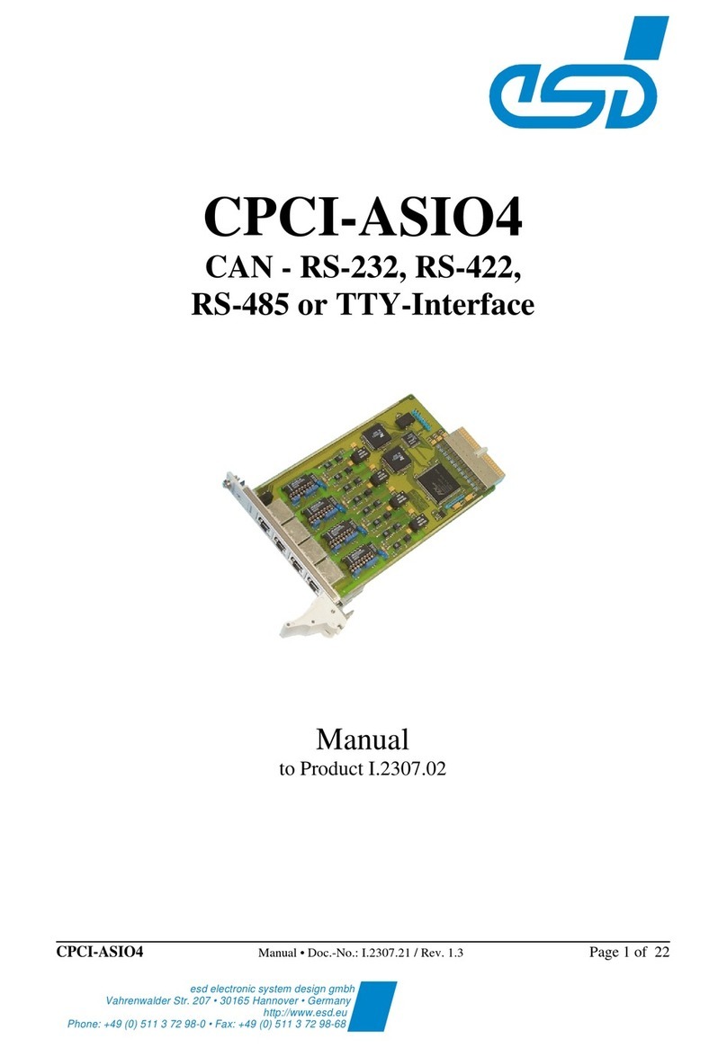
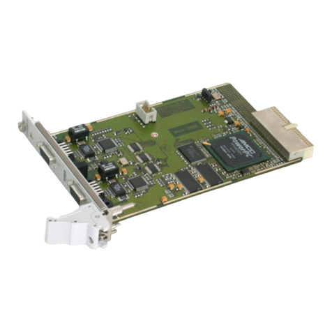
ESD CPCI-ASIO4 User manual

Serial Piggybacks
Hardware Manual • Doc.-No.: V.1930.21 / Rev. 4.1
Page 1 of 16
esd electronic system design gmbh
Vahrenwalder Str. 207 • 30165 Hannover • Germany
http://www.esd.eu
Phone: +49 (0) 511 3 72 98-0 • Fax: +49 (0) 511 3 72 98-68
Serial Piggybacks
RS-422-Adapter, RS-485-Adapter,
TTY-Adapter
Hardware Manual
to Product V.1930.02,
V.1930.04,
V.1930.06,
V.1930.08,
V.1930.10

Hardware Manual • Doc.-No.: C.2836.20 / Rev. 4.1
Serial PiggybacksPage 2 of 16
N O T E
The information in this document has been carefully checked and is believed to be entirely reliable.
esd makes no warranty of any kind with regard to the material in this document, and assumes no
responsibility for any errors that may appear in this document. In particular descriptions and technical
data specified in this document may not be constituted to be guaranteed product features in any legal
sense.
esd reserves the right to make changes without notice to this, or any of its products, to improve
reliability, performance or design.
All rights to this documentation are reserved by esd. Distribution to third parties and reproduction of
this document in any form, whole or in part, are subject to esd’s written approval.
© 2016 esd electronics system design gmbh, Hannover
esd electronic system design gmbh
Vahrenwalder Str. 207
30165 Hannover
Germany
Phone: +49-511-372 98-0
Fax: +49-511-372 98-68
E-mail: [email protected]
Internet: www.esd.eu
This manual contains important information and instructions on safe and efficient
handling of the module. Carefully read this manual before commencing any work and
follow the instructions.
The manual is a product component, please retain it for future use.
Trademark Notices
All trademarks, product names, company names or company logos used in this manual are reserved by their respective
owners.

Serial Piggybacks
Hardware Manual • Doc.-No.: V.1930.21 / Rev. 4.1
Page 3 of 16
Document file:
I:\Texte\Doku\MANUALS\SONSTIGE\SER-PIGG.BCK\Englisch\Serial_Piggybacks_Manual_en_41.wpd
Date of print: 2016-10-24
PCB version: TTY2_PLT
RS422SM2
P-RS485-1
Changes in the chapters
The changes in the user’s manual listed below affect changes in the hardware, as well as changes in
the description of the facts only.
Version Chapter Changes versus previous version
4.1
- Warning Messages and Safety Instructions inserted, Classification inserted
1. Editorial changes
2. Figure of RS-422 schematic diagram changed
3., 3.2 Description of RS485-Adapter Internal Termination inserted
4.2 Description of TTY-Adapter active
5. Chapter moved and revised
Further technical changes are subject to change without notice.

Hardware Manual • Doc.-No.: C.2836.20 / Rev. 4.1
Serial PiggybacksPage 4 of 16
Classification of Warning Messages and Safety Instructions
This manual contains noticeable descriptions, warning messages and safety instructions, which you
must follow to avoid personal injuries or death and property damage.
This is the safety alert symbol.
It is used to alert you to potential personal injury hazards. Obey all safety messages and
instructions that follow this symbol to avoid possible injury or death.
DANGER, WARNING, CAUTION
Depending on the hazard level the signal words DANGER, WARNING or CAUTION are used to
highlightsafetyinstructionsandwarningmessages.Thesemessagesmayalsoincludeawarningrelating
to property damage.
DANGER
Danger statements indicate a hazardous situation which, if not avoided, will result in
death or serious injury.
WARNING
Warning statements indicate a hazardous situation that, if not avoided, could result in
death or serious injury.
CAUTION
Caution statements indicate a hazardous situation that, if not avoided, could result in
minor or moderate injury.
NOTICE
Notice statements are used to notify people on hazards that could result in things other than personal
injury, like property damage.
NOTICE
This NOTICE statement indicates that the device contains components sensitive to
electrostatic discharge.

Serial Piggybacks
Hardware Manual • Doc.-No.: V.1930.21 / Rev. 4.1
Page 5 of 16
Safety Instructions
When working with Serial Piggybacks follow the instructions below and read the manual
carefully to protect yourself and Serial Piggybacks from damage.
The device is a built-in component. It is essential to ensure that the device is mounted in a way
that cannot lead to endangering or injury of persons or damage to objects.
In case of damages to the device, which might affect safety, appropriate and immediate
measures must be taken, that exclude an endangerment of persons and domestic animals and
property.
Current circuits which are connected to the device have to be sufficiently protected against
hazardous voltage (SELV according to EN 60950-1).
The Serial Piggybacks may only be driven by power supply current circuits, that are contact
protected. A power supply, that provides a safety extra-low voltage (SELV or PELV)
according to EN 60950-1, complies with this conditions.
The Serial Piggybacks have to be securely installed before commissioning.
Protect the Serial Piggybacks from dust, moisture and steam.
Protect the Serial Piggybacks from shocks and vibrations.
The Serial Piggybacks may become warm during normal use. Always allow adequate
ventilation around the Serial Piggybacks and use care when handling.
Do not operate the Serial Piggybacks adjacent to heat sources and do not expose it to
unnecessary thermal radiation. Ensure an ambient temperature as specified in the technical
data.
DANGER
Hazardous Voltage - Risk of electric shock due to unintentional contact with
uninsulated live parts with high voltages inside of the system into which the Serial
Piggybacks is to be integratred.
All current circuits which are connected to the device have to be sufficiently
protected against hazardous voltage (SELV according to EN 60950-1).
NOTICE
Electrostatic discharges may cause damage to electronic components.
To avoid this, please discharge the static electricity from your body before you
touch the Serial Piggybacks.
Furthermore, you should prevent your clothes from touching the Serial
Piggybacks, because your clothes might be electrostatically charged as well.
Qualified Personal
This documentation is directed exclusively towards qualified personal in control and automation
engineering.
Theinstallationandcommissioningoftheproduct mayonlybecarriedoutbyqualifiedpersonal,which
is authorized to put devices, systems and electric circuits into operation according to the applicable
national standards of safety engineering.


Hardware Manual • Doc.-No.: C.2836.20 / Rev. 4.1
Serial PiggybacksPage 6 of 16
Intended Use
The intended use of the Serial Piggybacks is the operation as RS-422, RS-485 or TTY Adapter.
The esd guarantee does not cover damages which result from improper use, usage not in accordance
with regulations or disregard of safety instructions and warnings.
The Serial Piggybacks are intended for installation on suitable esd boards only.
The operation of the Serial Piggybacks in hazardous areas, or areas exposed to potentially
explosive materials is not permitted.
The operation of the Serial Piggybacks for medical purposes is prohibited.
Service Note
The Serial Piggybacks does not contain any parts that require maintenance by the user. The Serial
Piggybacks do not require anymanual configuration of the hardware. Unauthorized intervention in the
device voids warranty claims.
Disposal
Deviceswhichhavebecomedefectiveinthelongrunhavetobedisposedinanappropriate wayorhave
to be returned to the manufacturer for proper disposal. Please, make a contribution to environmental
protection.

Serial Piggybacks
Hardware Manual • Doc.-No.: V.1930.21 / Rev. 4.1
Page 7 of 16
Contents
1. Overview ....................................................................8
2. RS-422 Piggyback ............................................................9
2.1SchematicDiagramRS-422Adapter............................................9
2.2Dimensions ..............................................................10
3. RS-485 Piggybacks ...........................................................11
3.1 Schematic Diagram of RS-485-Adapter . . . . . . . . . . . . . . . . . . . . . . . . . . . . . . . . . . . . . . . . 11
3.2 Schematic Diagram of RS-485-Adapter Internal Termination . . . . . . . . . . . . . . . . . . . . . . . 12
3.3Dimension ...............................................................13
4. TTY Piggyback ..............................................................14
4.1 Schematic Diagram TTY-Adapter passive . . . . . . . . . . . . . . . . . . . . . . . . . . . . . . . . . . . . . . 14
4.2 Schematic Diagram TTY-Adapter active . . . . . . . . . . . . . . . . . . . . . . . . . . . . . . . . . . . . . . . 14
4.3Dimensions ..............................................................15
5. Order Information ...........................................................16

Overview
Hardware Manual • Doc.-No.: C.2836.20 / Rev. 4.1
Serial PiggybacksPage 8 of 16
!
" # $ % & ' ( )
*
+
,
-
.
/
0
1
"%%234'(
5 & 6 7 8 7 9 4 : ; ' < 9
= > % > ? @ A 7 8 7 B
1. Overview
TheserialpiggybacksRS-422Adapter,RS-485Adapter,RS422-AdapterInternalTerminationandTTY
Adapter areadd-on PCBs which carry the drivers and transceivers forserial interfaces. Theydefine the
interface between the serial controller and the peripheral bus.
The pin assignment and the dimensions of the piggybacks are designed to fit in a special plug socket
that enables the user to realize a RS-422, RS-485, TTY or, using a RS-232 driver like e.g. the MAX232
a RS-232 interface.
The following figure shows the arrangement of the piggybacks and the RS-232 transceiver at the plug
sockets.
Figure 1: Plug-in socket dimensions and piggyback/RS-232 driver arrangement
Please read the manual of the carrier board for the resulting pin assignment of the serial interface
connector (e.g. DSUB9) at the carrier board.
The plug sockets have to be able to carry pins with a diameter of 0.5 mm.

RS-422 Piggyback
Serial Piggybacks
Hardware Manual • Doc.-No.: V.1930.21 / Rev. 4.1
Page 9 of 16
2. RS-422 Piggyback
2.1 Schematic Diagram RS-422 Adapter
Figure 2: Schematic diagram of the RS-422 Adapter

RS-422-Piggyback
Hardware Manual • Doc.-No.: C.2836.20 / Rev. 4.1
Serial PiggybacksPage 10 of 16
C
D
E
F
D
G
H
D
G
F
D
G
I J K L
M
D
N
O
P
Q
R S K T
C
M
D
H
U R
U S
U V
U W
U L
U X
U T
U YZ
R J
R R
R S
R V
R W
R L
R X
[
D
C
\
]
^
C
D
G
H
R K S T
R R K W V
_I`aIbcbde
fghc ijdkIld
_I`aIbcbde
mno pqrs
tunvw pqrs
x
y
z
{
|
|
2.2 Dimensions
Figure 3: Pin assignment and dimensions of the RS-422 Adapter

RS-485-Piggyback
Serial Piggybacks
Hardware Manual • Doc.-No.: V.1930.21 / Rev. 4.1
Page 11 of 16
3. RS-485 Piggybacks
The RS485-Adapter is available in two versions:
- RS485-Adapter, see chapter “Schematic Diagram of RS485-Adapter”
- RS485-Adapter Internal Termination (with internal termination of CAN), see chapter “Schematic
Diagram of RS-485-Adapter Internal Termination”
3.1 Schematic Diagram of RS-485-Adapter
Figure 4: Schematic diagram of the RS-485 Adapter
The RS-485 Adapter (V.1930.04) carries termination resistors that can be connected to the serial data
lines via external bridges.

RS-485-Piggyback
Hardware Manual • Doc.-No.: C.2836.20 / Rev. 4.1
Serial PiggybacksPage 12 of 16
3.2 Schematic Diagram of RS-485-Adapter Internal Termination
Figure 5: Schematic diagram of the RS-485 Adapter Internal Termination
In the version RS-485-Adapter Internal Termination (V.1930.10) the termination resistors on the
adapter are internally connected to the CAN bus signals.

RS-485-Piggyback
Serial Piggybacks
Hardware Manual • Doc.-No.: V.1930.21 / Rev. 4.1
Page 13 of 16
}
~
~
~
~
~
}
~
~
}
}
¡¢£¤¥¤¦§
¨©ª «¬®
¯°©±² «¬®
}
~
³
´
µ
¶
·¸¹º»¼ ½¼¾º¿»
ÀÁ¾Â ÃÄŠƸ»ÆÇ»º
¾Â º»ÈÉÊ¹Ç ËÇÉÇ»Ì
ÍÎÏÐÑÒÓ ÔÒÑÓÐ
¡¢£¤¥¤¦§
3.3 Dimension
Figure 6: Pin assignment and dimensions of the RS-485Adapters

TTY Piggyback
Hardware Manual • Doc.-No.: C.2836.20 / Rev. 4.1
Serial PiggybacksPage 14 of 16
4. TTY Piggyback
The TTY-Adapter is available in two versions:
- TTY-Adapter passive, see chapter “Schematic Diagram of TTY-Adapter passive”
- TTY-Adapter active, see chapter “Schematic Diagram of TTY-Adapter active”
4.1 Schematic Diagram TTY-Adapter passive
Figure 7: Schematic diagrams of the TTY-Adapter passive
The TTY piggyback is configured as a passive interface in default state (V.1930.06).
4.2 Schematic Diagram TTY-Adapter active
Figure 8: Schematic diagrams of the TTY-Adapter active
In the ‘TTY-Adapter active’ version (V.1930.08) the pins X2, X3 and X4 of the TTY-Adapter are
connected (-12 V). This can be done by a simple wire bridge at the top layer of the piggyback, because
the threepin are close to eachother. The TTYactive mode can onlybe used if the carrierboard supports
the necessary supply voltage of ±12 V.

TTY Piggyback
Serial Piggybacks
Hardware Manual • Doc.-No.: V.1930.21 / Rev. 4.1
Page 15 of 16
Õ
Ö
×
Ø
Õ
Ö
Ù
Ø
Ú
Ö
×
Û
Ö
Ü
Ý
Þ ßàá
×
Ö
â
ãäàå
Ø
×
Ö
â
æã
æä
æç
æè
æá
æé
æå
æêë
ãß
ãç
ãè
ãá
ãé
Ü
Ö
Ø
Ú
ãàäå
ããàèç
ãã
ãä
ìíçãå
ìíçãå
îÞïðÞñòñóô
õö÷ øùúû
üýöþÿ øùúû
Ø
Ö
Õ
â
îÞïðÞñòñóô
4.3 Dimensions
Figure 9: Pin assignment and dimensions of the TTY Adapter

Order Information
Hardware Manual • Doc.-No.: C.2836.20 / Rev. 4.1
Serial PiggybacksPage 16 of 16
5. Order Information
Type Designation Order no.
RS422-Adapter RS-422 Add on V.1930.02
RS485-Adapter RS-485 Add on V.1930.04
RS485-Adapter
internal
termination RS-485 Add on with internal termination V.1930.10
TTY-Adapter
passive TTY Add on for passive TTY interfaces V.1930.06
TTY-Adapter
active
TTY Add on for active TTY interfaces
(TTY-Adapter as V.1930.06 but configured as an active
TTY interface), for usage with carrier boards that
support ±12 V only (see page 14)
V.1930.08
Table 1: Order information
PDF Manuals
Manualsare availablein English and usuallyin Germanas well.For availabilityof Englishmanualssee
the followingtable. Please download the manuals as PDF documents from our esd website www.esd.eu
for free.
Manuals Order No.
Serial Piggybacks ME Manual in English V.1930.21
Table 2: Available manuals
Printed Manuals
If you need a printout of the manual additionally, please contact our sales team: [email protected] for a
quotation. Printed manuals may be ordered for a fee.
Other manuals for CPCI-ASIO4
1
Table of contents
Other ESD Computer Hardware manuals

ESD
ESD PMC-CPU/440 User manual

ESD
ESD EPPC-405-UC User manual

ESD
ESD PMC-CAN/402-4-FD User manual

ESD
ESD CAN-PCIe/200 User manual

ESD
ESD CAN-PCIeMini/402-2 User manual

ESD
ESD CPCI-ASIO4 User manual

ESD
ESD VME-DIO32-C User manual

ESD
ESD CPCI-405 User manual

ESD
ESD ECS-CPCIs/FPGA User manual

ESD
ESD VME-PMC-CPU/2 User manual