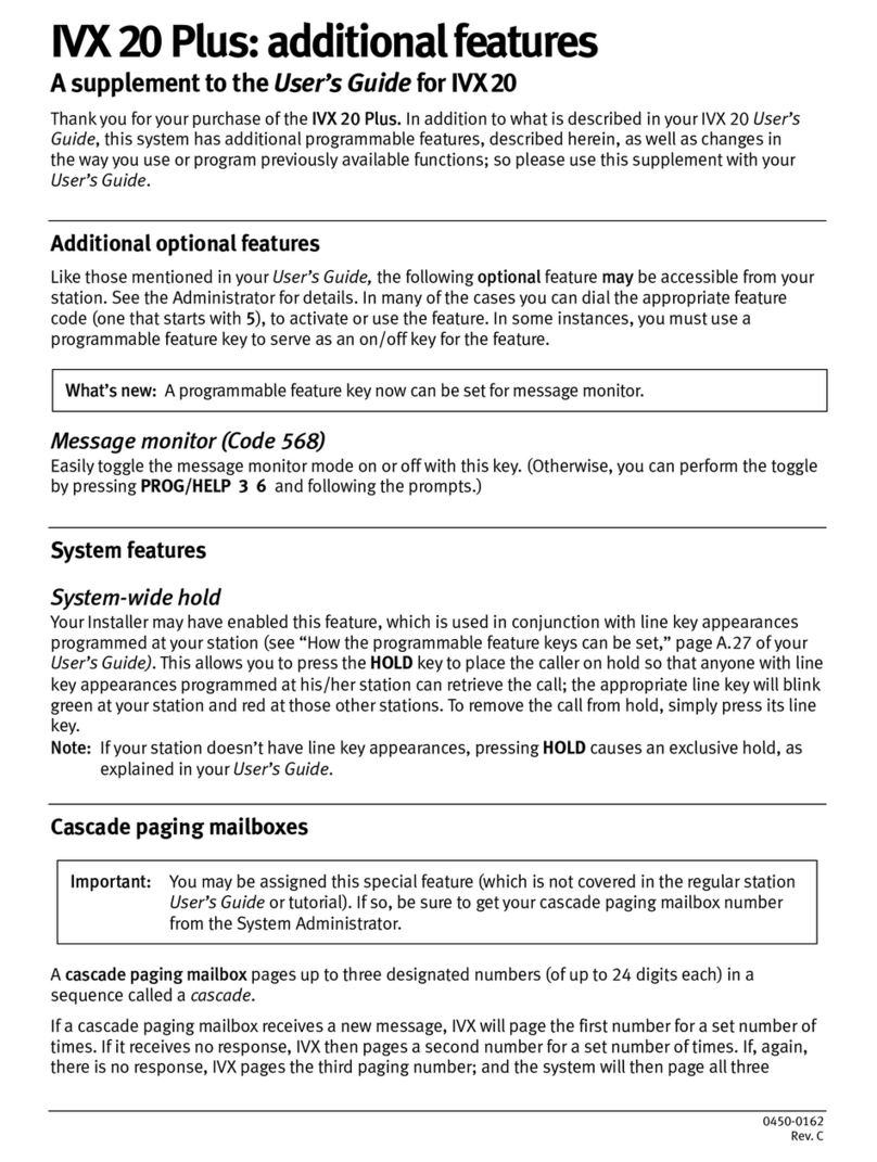
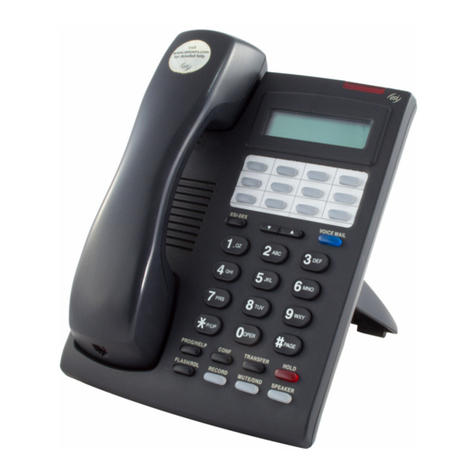
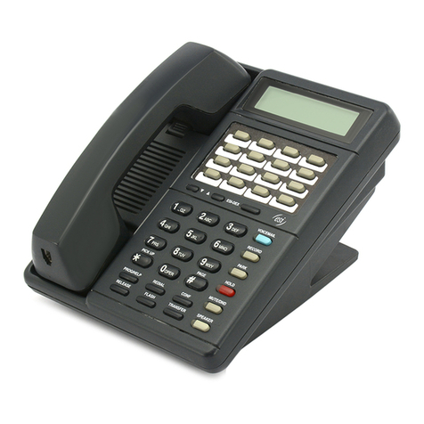
ESI IP 200 User manual

Installation Manual
0450-0196
Rev. D

About ESI
ESI (Estech Systems, Inc.) is a privately held corporation based in Plano, Texas, in the internationally known
“Telecom Corridor.” Founded in 1987, ESI designs and builds innovative telecommunications products for
businesses like yours. Because of their powerful combination of value and features, ESI products are consis-
tently recognized by industry publications and leaders. In fact, ESI also creates telecommunications products
for major companies to market under their well-known brand names.
Copyright © 2002 ESI (Estech Systems, Inc.).
Visit ESI on the Web at http://www.esi-estech.com.
IVX is a registered trademark of Estech Systems, Inc. Ethernet is a registered trademark of Xerox Corporation. Motorola and ColdFire are
registered trademarks of Motorola, Inc. Rayovac is a registered trademark of Rayovac Corporation. Act! is a registered trademark of
Symantec Corporation. Goldmine is a trademark of Goldmine Software Corporation. Microsoft, Windows, NT and Outlook are registered
trademarks of Microsoft Corporation. Panasonic and DBS are registered trademarks of Matsushita Electric Corporation of America. Novell
and Netware are registered trademarks of Novell, Inc.
IP Series and IVX Series products are protected by U.S. Patents No. 6,067,349 and 6,252,944, and others pending.
ESI is an ISO 9001-certified company.

Table of contents
General description.............................................................................................................A.1
Hardware overview/installation............................................................................................ B.1
System programming: an introduction.................................................................................. C.1
Function 1: System parameters ............................................................................................ D.1
Function 11: Initialize............................................................................................................................................................D.1
Functions 12 and 13: Installer and Administrator passwords...........................................................................................D.1
Function 14: Set time/date...................................................................................................................................................D.1
Function 15: System timing parameters...............................................................................................................................D.2
Function 16: System feature parameters..............................................................................................................................D.3
Function 17: System speed-dial ...........................................................................................................................................D.3
Function 18: Serial maintenance port baud rate ..................................................................................................................D.4
Function 2: CO lines..............................................................................................................E.1
Function 21: CO line programming ....................................................................................................................................... E.1
Function 22: CO access/denial tables ................................................................................................................................E.10
Function 23: CO line parameters........................................................................................................................................ E.14
Function 24: Caller ID.......................................................................................................................................................... E.16
Function 3: Extension programming....................................................................................... F.1
Function 31: Extension definition and routing.......................................................................................................................F.1
Function 32: Extension feature authorization........................................................................................................................F.9
Function 33: Department programming ..............................................................................................................................F.11
Function 35: Extension button mapping..............................................................................................................................F.13
Function 4: Auto attendant programming .............................................................................. G.1
Function 41: Auto attendant branch programming ..............................................................................................................G.1
Function 42: Announce extension number...........................................................................................................................G.5
Function 43: Automatic day/night mode table.....................................................................................................................G.5
Function 5: Voice mail programming ..................................................................................... H.1
Function 51: Maximum message length ..............................................................................................................................H.1
Function 52: Message purge control.....................................................................................................................................H.1
Function 53: Guest/info mailboxes ......................................................................................................................................H.2
Function 54: Group mailboxes and the broadcast mailbox..................................................................................................H.3
Function 55: Message notification........................................................................................................................................H.4
Function 56: Cascade paging mailboxes..............................................................................................................................H.5
Function 57: Q & A mailboxes...............................................................................................................................................H.6
Function 58: Message move and delete...............................................................................................................................H.7
Function 6: Recording...........................................................................................................I.1
Function 61: Re-record system prompts and ID branches..................................................................................................... I.1
Function 62: Record directory names .................................................................................................................................... I.2
Function 63: Message-on-hold (MOH) programming............................................................................................................ I.3
Function 7: Reports .............................................................................................................. J.1
Function 8: IP PBX programming........................................................................................... K.1
Function 82: Local IP PBX programming...............................................................................................................................K.1
Function 83: Esi-Link programming ...................................................................................................................................... K.4
Index
Appendix I: User’s Guide • Appendix II: Worksheets
(This page included for pagination purposes only.)

IP Series Installation Manual General description
A.1
General description
ESI’s IP Series (IP 200 and IP 40) IP telephony products are advanced business telecommunications
systems, each of which includes not only phone service but voicemail, an automated attendant,
automatic call distribution, and computer integration. These features are all provided over standard
Ethernet cabling, using the Internet Protocol and certain other protocols from the TCP/IP suite.
In IP telephony, voice is digitized at the telephone and then converted to IP data packets at the
telephone. Those packets are sent across an IP data network and then converted back to a voice
signal at the other party’s IP telephone or at the IP PBX for connections to outside lines.
The IP Series consists of an IP Feature Phone, the Remote IP Feature Phone and two models of the
IP PBX.
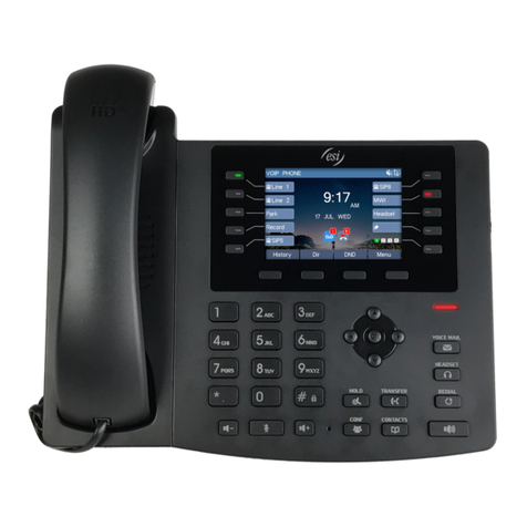
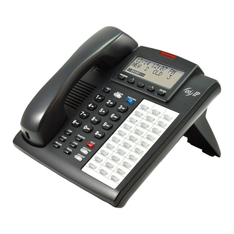
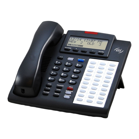
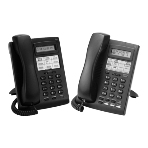
The IP Feature Phone provides all the features and functionality expected of business phones. It
looks and feels exactly like ESI’s popular IVX®digital telephone, but it connects to the system over
the same Ethernet®cables used by PCs and data servers. Voice is carried over the network at an
uncompressed 64 Kbps — the highest quality available.
The Remote IP Feature Phone, like the IP Feature Phone, is a full-featured business phone but
provides the additional benefit of working from a remote site connected into the main office. Like
an office extension, the Remote IP Feature Phone connects the remote user to the office environ-
ment and, thus, is ideal for the tele-worker or the executive home office. A suitable high-speed data
connection, such as over a WAN or high-speed Internet connection, is required between the remote
site and the main office. Voice is carried in a high-quality, compressed 22 Kbps format.
The two IP PBXs differ only in the number of supported CO lines and stations. The IP 200 can
be configured to handle up to 66 CO lines, 30 analog ports and 96 stations, while the IP 40 can
handle up to 30 lines, nine analog ports and 28 stations. The IP PBXs connect directly to an
Ethernet network and are both rack-mountable and wall-mountable.
Telephone system features
The IP Series PBXs support a comprehensive array of robust features, including:
• Impressive expansion capability – Can handle up to 66 CO lines and 96 stations.
• T1 and ISDN PRI support – Can connect to higher-bandwidth lines.
• IP Feature Phone – Compact and rugged design includes a high-quality speakerphone, large and
informative multi-functional display, and a specially designed key layout with several dedicated
keys to minimize or eliminate the need to memorize codes. The IP phone is TAPI-compliant, and
a TAPI driver is available as a free download from the ESI Web site.
• Extensive help – Verbal User Guide™uses spoken and displayed help prompts to assist every-
one from the installer through the administrator down to the least experienced end user. Easily
accessible with one press of the PROG/HELP key.
• Enhanced caller ID – Allows one-touch automatic message return.
• Live call recording — Can record any conversation or personal memo, with moving or copying of
any recording to another user’s voice mailbox (see “Voice mail features,” below).
• Call waiting — Includes helpful display, showing both calls’ caller ID information, and easy one-
key toggling between calls.
• Conference calling — Includes 24 conference bridges, and a conference may contain up to four
parties, so the IP Series can support six conferences of four parties each or eight conferences of
three parties each.

General description IP Series Installation Manual
A.2
• Esi-Dex™speed-dialing — Calls any number from any of the three separate lists (personal, sta-
tion, and system); uses Caller ID information or direct keypad entries.
• Dedicated overhead paging interface — Allows overhead paging through the user’s own over-
head paging system.
• 911 alert — Provides immediate line access if any station dials 9 1 1 to report an emergency;
sends a message via the serial port indicating the start date, time, station number and end-time of
the 911; also sounds a warning tone at the operator station and displays (for example):
911 CALL FROM
X102 JOHN JAMES
Note: You can dial 9 1 1 from any station, even one usually restricted from outside line access in
Function 31 (see pages F.1–F.8).
Remote network features (VoIP)
In addition to a robust set of telephony features, the IP Series PBXs have the capability for extend-
ing PBX operation to any location that has access to a suitable high-speed data connection. This
capability is provided with the Remote IP Feature Phone and Esi-Link.
• Remote IP Feature Phone — Ideal for the remote site installation requiring one, or no more than
a few, extensions. Once installed, the remote user is provided a near identical capability and
connectivity of the phone user in the main office. Numerous remote sites can be supported from
a single IP PBX. Refer to the Remote IP Feature Phone Product Overview (#0450-0213) and Using
the Remote IP Feature Phone (#0450-0282) for more information. The Remote IP Feature Phone
Installation Manual (#0450-0263) provides additional installation information intended to be
used with this manual.
• Esi-Link — Provides the capability of connecting up to 100 IP PBXs at different locations into a
single private phone system. The ESI IP PBX features that so far have been available to a single
location can now be extended across several locations, greatly enhancing the integration oppor-
tunities of a business with multiple locations. Refer to the Esi-Link Product Overview for a full
explanation of Esi-Link capabilities.
Voice mail features
• 16 built-in voice mail ports — These are in addition to the up-to-192 possible call-processing
ports; thus, you may build the system to its maximum for call-handling without having to bal-
ance voice mail needs versus call-handling needs.
• Highest-grade voice quality (64 Kbps sampling) for voice mail and other storage of voice messages.
• Nine message-on-hold sources — Among these are three prerecorded tracks and five customer-
recordable tracks; also supports live input.
• Off-premises message delivery.
• Urgent messages — Can deliver higher-priority messages first.
• Several different mailbox types, including group, broadcast, informational, cascade paging
and Q & A.
• Message Recycle Bin (undelete) — Remembers, and can restore, each mailbox’s 10 most re-
cently deleted messages
• Quick Groups™— Makes it easy to leave voice mail messages for several users.
• Quick Move™— Allows recording conversations or calls directly into a designated mailbox.

IP Series Installation Manual General description
A.3
• Virtual Mailbox Key™— Allows easy monitoring of a second mailbox.
• New-message skip — Skip a new message and have it appear as “new” the next time.
• Message monitor key — Toggle the live-call screening feature with a single programmable key.
• Message move and delete — Move-and-save, or move-and-delete, messages.
Call-handling features
• AutoPage™— Allows a caller, when forwarded to voice mail, to page a station user.
• Off-Premises “reach me” — Lets callers reach their party while he or she is off premises.
• Virtual Answer Key™— Users can play pre-programmed prompts to inbound callers.
• Caller ID missed-call key — Stores caller ID for ten most recent missed calls.
• Auto-attendant trunk-to-trunk transfer — Create an auto-attendant outdial branch without the
need for Centrex lines.
• Separate hold/park recall timers — Separate recall timers for calls on park and hold.
• System-wide hold — Puts the CO line on hold, after which any user can pick up the call by press-
ing the line key.
• System-connect tone control — Allows the installer or administrator to disable the connect tone.
• CO line labeling — Labels the CO lines and has them appear in the display when they ring.
• QuickPage™— Allows a station user to park a call and automatically page another user.
Auto attendant features
• Six levels, 100 branches — Allow you and your customer to set up a more caller-friendly
answering environment, including a company directory.
• Virtually unlimited call routing — Includes off-premises transfer, pager notification, more.
ACD features
• Routes calls within designated departments for quickest possible call answering.
• Uses IP Feature Phone display to provide up-to-the-second information on queues and
wait times.
• Sends calls to longest-idle agent.

General description IP Series Installation Manual
A.4
(This page included for pagination purposes only.)

IP Series Installation Manual Hardware overview/installation
B.1
Hardware overview/installation
Each IP Series IP PBX consists of a single cabinet with:
• Two or 10 expansion slots (IP 40 and IP 200, respectively)
• An external transformer
• An IP module that includes:
– A mainboard
– A Memory Module (hard disk drive)
– A Local Network Card
– An optional Remote Network Card, in either three-channel or 12-channel configuration
Each IP PBX is shipped with one port card (see page B.3 for the port card options). The port cards
are interchangeable between the IP 200 and IP 40.
IP 200
The rack-mountable IP 200 measures
5.5” H x 17.5” W x 9” D. Optional
external “ears” attach to each side for
mounting the IP 200 in a 19” data rack
or on a wall.
The rightmost third of the IP 200
houses the IP module, and the leftmost
two-thirds houses the port cards. The port cards are accessible from the front of the IP 200. The first
port card is in Slot 1 (farthest to the right), and additional port cards are added from right to left.
The IP 200 has 10 available port-card slots.
The IP module consists of:
• Mainboard — Provides the AC power connector, two serial ports, and the MOH connector.
• Local Network Card (LNC) — Provides an RJ-45 10/100Base-T Ethernet connector and an RJ-11
overhead paging port.
• Memory Module — A hard disk drive that contains the call-processing software and provides
storage for voice mail.
The mainboard is secured to the floor of the IP module with
metal standoffs that also provide support for the LNC. The
network card sits on top of the standoffs and is secured to
them with screws. The Memory Module is mounted on a steel
plate, which in turn sits on top of the sheet metal that forms the
sides of the IP module and is secured by screws.
The mainboard and the LNC are joined by means of a
50-pin ribbon cable that runs from J9 on the mainboard to J1 on the LNC. The Memory Module is
joined to both of the circuit boards by means of a standard 40-pin IDE cable that connects to JP9 on
the LNC and JP2 on the mainboard. A standard four-pin power connector runs from J8 on the main-
board to the back of the Memory Module.
The Local Network Card (LNC) connects to the backplane by means of a 60-pin cable that uses J6 on
the Ethernet card and slides onto U3 on the backplane. The optional Remote Network Card (RNC) is
inserted into the 72-pin socket U13 on the LNC, located directly behind the RJ-11 overhead-paging
port. (Refer to each card’s installation instructions for more details.)
Slot 1
(shown filled)

Hardware overview/installation IP Series Installation Manual
B.2
IP 40
The IP 40 is a smaller version of the IP 200.
It measures 11” W x 3 ½” H x 9” D. The
optional external “ears” will allow it to be
mounted in a 19” data rack; alternatively, it
can be set on a tabletop, or a separately
orderable kit will allow wall-mounting.
The IP module (the mainboard and the
Local Network Card) is on the right-hand of the IP 40. The IP 40 provides two slots for port cards. On
the left-hand side, the Memory Module is mounted in the floor of the IP 40. The first port card is
installed horizontally, just above the Memory Module, and the second port card can be installed
above the first.
Port card #1 is attached directly to J7 on the LNC via a 60-pin ribbon cable. Port card #2 is attached
to J8. As with the IP 200, the mainboard’s J9 connects to the LNC’s J1, and the Memory Module’s
IDE cable connects to JP9 on the LNC and JP2 on the mainboard. The Memory Module is powered by
a 4-wire power cable connected to the mainboard’s J8. The optional Remote Network Card (RNC)
is inserted into the 72-pin socket U13 on the LNC, located directly behind the RJ-11 overhead-
paging port.
The front of the IP 40 features an AC power connector, two serial ports, an MOH connector, one
RJ-45 10/100Base-T Ethernet connector, and an RJ-11 overhead paging port.
Main board
The main board combines leading-edge hardware components — including a Motorola®
ColdFire®processor and DSP structure — along with proprietary operating system software. The
board provides:
• System control of the Memory Module and port cards
• Two standard RS-232C DB9 serial ports
• A built-in 33.6 Kbps modem for remote access
• An external paging-device interface
• MOH interface
Local Network Card (LNC)
The Local Network Card (LNC) provides the 10/100Base-T RJ-45 interface that allows the IP system
to connect to the Ethernet network. The LNC features highly configurable DSP (digital signal proces-
sor) technology that manages the flow of traffic among the port cards and converts IP packets into
PCM traffic for transmission over the PSTN. This card also provides through the RJ-11 jack a dry-
contact interface, used by popular overhead paging systems.
Memory Module
The Memory Module — a hard disk drive with proprietary formatting — contains all system program
and configuration data, along with pre-loaded voice prompts. The Memory Module provides 140
hours of voice storage at the industry's highest-quality sampling rate: 64 kilobits/second.

IP Series Installation Manual Hardware overview/installation
B.3
Remote Network Card (RNC)
The Remote Network Card (RNC) provides G.729A compression to support Remote IP Feature Phones
and multi-site installation using Esi-Link. The RNC is offered in two versions that can be added to
the IP 200 or IP 40. The RNC 3 provides three channels of voice compression; the RNC 12 provides
12. The RNC compresses the two-way talk path, 64 Kbps each way, into 8-Kbps talk channels. Each
compressed bi-directional channel, voice and control signaling, requires only 22 Kbps. This com-
pression makes remote connection between IP PBX and Remote IP Feature Phones practical.
Port card options
Three port cards are available for creating various system configurations:
Card What it provides
303 3 loop-start lines via an RJ-11 connector, 3 analog device ports via an RJ-11 connector
600 6 loop-start lines via two RJ-11 connectors
DLC Either 24 loop-start/ground-start/E&M/E&M DNIS/DID trunks, or 23 digital ISDN lines
(23B + 1D), via an RJ-48 connector
Note: The IP 200 and the IP 40 will have one of these cards installed in the first card slot
upon delivery.
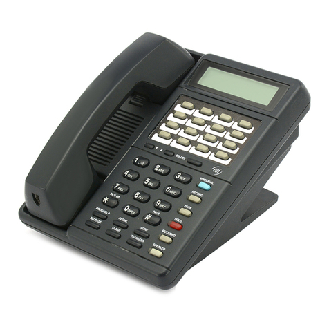
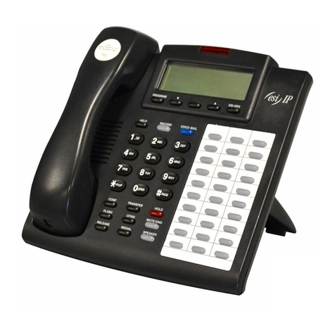
IP Feature Phones
The IP Feature Phone is equipped with speakerphone, 16-character-by-2-line LCD display, and fixed
and programmable feature keys. IP phones provide two RJ-45 connectors – one for connecting to
the network and one for another Ethernet device – and a connector for a 64-key expansion console.
AC power is provided through a small external grounded transformer with a 12-foot cord. A 12-foot
Category-5 Ethernet cable is provided with each phone.
Remote IP Feature Phone
The Remote IP Feature Phone is virtually identical to the IP feature Phone. The physical appearance
is the same. The operation varies in only a few minor ways. The critical difference is the G.729a
processor contained with the Remote IP Feature Phone. This processor performs the voice com-
pression required to make remote IP telephony practical.

Hardware overview/installation IP Series Installation Manual
B.4
64-Key Expansion Console
The 64-Key Expansion Console adds 64 additional programmable feature keys to a station. The
Console is connected to its host phone via a standard six-conductor silver-satin cable that attaches
to the appropriate connector on the underside of the IP Feature Phone. The Console does not use
one of the 96 available station ports. AC power for the expansion console is obtained from the IP
telephone’s external transformer, through the connector cable.
Note: Up to 20 consoles can be installed in a fully-configured system.
System capacity
IP 200
The IP 200’s 10 slots can hold any combination of port cards (with a maximum of two DLCs, whether
configured for T1 or PRI, supported). If two DLCs are installed and each of them provides its full 23
or 24 channels, the IP 200 will support only 18 to 20 more CO lines in its remaining eight slots.
Max configurations for IP 200
C A R D S Y I E L D
DLCs
(23 or 24
chs. ea.)
600
cards
303
cards
RNC12
cards
CO
lines
Analog
ports
Remote
channels
IP
stations
2 — 8 — 64–66 24 — 96
2 3 — — 64–66 — — 96
1 5 4 — 65–66 12 — 96
— 10 — — 60 — — 96
— — 10 — 30 30 — 96
2 1 7 1 64–66 21 12 96
IP 40
The IP 40’s two slots can hold up to one DLC; each can hold a 303 Card or 600 Card. The maximum
IP 40 configuration would include one 600 Card, one DLC and an RNC12 card: this yields 29 to 30
CO lines and 28 IP stations (of which up to 12 can be remote IP stations).

IP Series Installation Manual Hardware overview/installation
B.5
Cautions
Important: This information complies with the requirements of Underwriters’ Laboratories
(UL) and UL Standard 1950.
When using this telephone equipment, always exercise basic safety precautions in order to minimize
the risk of fire, electric shock or injury to persons. Before proceeding, please read the following:
The airflow vents on the IP PBX must be free of obstruction for proper cooling. Similarly, do not
install the IP PBX in areas of extreme heat or improper ventilation. Never insert objects of any kind
through the ventilation slots on the IP PBX; doing so may result in contact with dangerous voltages
— or cause an electrical short capable of producing fire or shock.
Do not use liquids or aerosols to clean any IP equipment; rather, use a cloth that is only slightly damp.
The IP telephone/voice-mail system contains no components that are serviceable by
either non-dealers or non-manufacturer technicians. All service must be referred to the dealer for
further handling.
To reduce the riskof fire, use only 26 AWG or better telecom wire.
Power supply (24V)
Always disconnect the power supply and telephone lines from the IP PBX before opening the case
for service or component disassembly or replacement.
Heed all warnings and instructions in documentation or marked on the IP PBX or peripheral equipment.
Fuse
Contact the factory before attempting to replace the fuse. The 5.0A fuse is located on the mother-
board directly next to the power jack marked with “F1.”
Battery
Caution: There is a danger of explosion if the onboard lithium battery is incorrectly replaced.
Replace only with Rayovac®BR1225 (or equivalent). Dispose of used batteries accord-
ing to the battery manufacturer’s instructions.

Hardware overview/installation IP Series Installation Manual
B.6
Regulatory information
United States of America
Registration
The CO line telephone numbers, FCC registration number, and ringer equivalence number (REN) of this equipment must be
provided to the telephone company before installation. (See below for FCC registration number and ringer equivalence number.)
FCC Part 15
This equipment has been tested and found to comply with the limits for a Class A digital device, pursuant to Part 15 of the
FCC Rules. These limits are designed to provide reasonable protection against harmful interference when the equipment is
operated in a commercial environment. This equipment generates, uses and can radiate radio frequency energy and — if
not installed and used in accordance with the instruction manual — may cause harmful interference to radio communica-
tions (in which case, the user will be required to correct the interference at his/her own expense).
FCC Part 68
Registration Number: 1T1USA-33727-MF-E
Ringer equivalence number (REN): 0.5
Dominion of Canada
Notice
The Industry Canada label identifies certified equipment. This certification means that the equipment meets telecommu-
nications network protective, operational and safety requirements as prescribed in the appropriate Technical Equipment
Technical Requirements document(s). The Department does not guarantee the equipment will operate to the user’s
satisfaction.
Before installing this equipment, users should ensure that it is permissible to be connected to the facilities of the local
telecommunications company. The equipment must also be installed using an acceptable method of connection. The
customer should be aware that compliance with the above conditions may not prevent degradation of service in some
situations.
Repairs to certified equipment should be coordinated by a representative designated by the supplier. Any repairs or
alterations made by the user to this equipment, or equipment malfunctions, may give the telecommunications company
cause to request the user to disconnect the equipment.
Users should ensure for their own protection that the electrical ground connections at the power utility, telephone lines
and internal metallic water pipe system, if present, are connected together. This precaution may be particularly important
in rural areas. Caution: Users should not attempt to make such connections themselves, but should contact the appropri-
ate electrical inspection authority, or electrician, as appropriate.
Ringer equivalence number (REN): 0.5
Notice
The ringer equivalence number (REN) assigned to each terminal device provides an indication of the maximum number of
terminals allowed to be connected to a telephone interface. The termination on an interface may consist of any combina-
tion of devices subject only to the requirement that the sum of the RENs of all the devices does not exceed 5.

IP Series Installation Manual Hardware overview/installation
B.7
Hardware installation
Site location
As with most electronic equipment, the environmental conditions are very important, and the site
should be chosen using good common sense. Provide a dry, clean, and accessible location.
The IP PBX can be co-located in either the telephone equipment room or the data distribution rack.
Ambient room
temperature must
be between 40º
and 80ºFahrenheit.
Do not place the
equipment near
high-voltage
electrical equip-
ment or lines.
The IP 200 can be
mounted in a 19”
data rack by
attaching the
optional ears to the
sides of the unit, at
the front. These
ears provide the
necessary width to
allow the unit to be screwed into the uprights on the rack. When the ears are mounted to the sides
of the unit, at the back, the IP 200 can be mounted on a wall. ESI recommends that the IP PBX be
mounted on ¾” or thicker plywood.
The IP 40 is significantly narrower than the IP 200. It is designed more as a tabletop model and
therefore is not normally rack-mounted. However, an optional rack-mount kit provides ears that will
allow the IP 40 to be mounted in a 19” data rack or on the wall.
Network design
The inherent design and construction of a data network will have a direct impact on the operation
of an IP telephony system. Proper implementation of networking features and functions — e.g.,
segmentation, available bandwidth and Quality of Service (QoS) — are crucial to the proper opera-
tion of IP telephony devices. Analysis tools such as Esi-Networx can be used as part of an overall
network assessment to determine whether an existing data network is suitable for carrying IP
telephony traffic.
Status
CO
Lines
CO
Lines
Status
CO
Lines
CO
Lines
Status
Analog
Ports
CO
Lines
Status
T1
Activity 10/100
LAN
HDD Status
123
456
789
0
PAGE
123
456
789
0
PAGE
123
456
789
0
PAGE
Typical installation (IP 200 shown)

Hardware overview/installation IP Series Installation Manual
B.8
Site cabling requirements
Proper data network cabling is an important component of a reliable IP telephony installation. All
cabling for the IP Series PBX and IP Feature Phones should meet IEEE 802.3 requirements or
EIA/TIA 568B Commercial Building Telecommunications Cabling Standards:
• If the IP Series PBX and IP Feature Phones are to be connected to a 100Base-T Ethernet network,
the cable length between the IP Feature Phone and the hub or switch cannot exceed 100 meters
(approximately 328 feet). The IEEE 802.3 standard does allow up to two repeaters (Ethernet
hubs or switches) for extending the distance to the IP Feature Phone.
• If the IP Series PBX and IP Feature Phones are to be connected to a 10Base-T Ethernet network,
the cable length between the IP Feature Phone and the hub or switch cannot exceed 600 feet. The
distance can be extended with the addition of up to two repeaters (Ethernet hubs or switches).
Rack-mounting the IP 200
1. Screw the optional “ears” onto the
forward side-screw receptacles of
the IP 200 chassis.
2. Mount the IP 200 chassis on
the rack.
Wall-mounting the IP 200
1. Screw the optional “ears” onto the
rear side-screw receptacles of the
IP 200 chassis.
2. Mount the IP 200 chassis onto the wall.

IP Series Installation Manual Hardware overview/installation
B.9
Rack-mounting the IP 40
1. Screw the optional
“ears” onto the
IP 40 chassis.
2. Mount the
IP 40 chassis
on the rack.
Port card installation/removal
Adding or removing port cards will require that the system be powered off. Wear a grounding strap
and avoid unnecessary movement while handling the circuit boards.
Unplug the power supply and any cables. Turn the thumbscrews counterclockwise to remove the IP
module and the port cards. (Blank port covers will need to be removed with a Phillips screwdriver.)
IP 200
It will be necessary to give the port cards
an initial tug to dislodge them from the
backplane in the back of the unit.
Similarly, when inserting the cards,
give them a slight push to seat them in
the backplane. Port cards must be
installed starting from the rightmost card
slot. Don’t leave empty card slots be-
tween installed port cards.
The LNC in the IP module is connected to
the backplane by a stiff cable. Remove
the top panel of the IP 200 to expose the
access hole in the top of the chassis.
Carefully pull the module forward and
reach in through the access hole to
remove the cable from the card.

Hardware overview/installation IP Series Installation Manual
B.10
IP 40
The port cards are attached by individual cables to
the Local Network Card in the IP system. Remove the
screws holding the top cover to the chassis and lift
the cover straight up. This will expose the interior of
the IP 40, and the cables can be detached from the
port cards and/or the LNC. The cables are keyed.
The first port card’s cable will be attached to J7 on
the LNC. The second port card will attach to J8.
Memory Module
Note: The Memory Module has a proprietary formatting scheme – do not attempt to install a
non-ESI drive.
Replacing the Memory Module will require that the system be powered off. Replacement Memory
Modules are available only from ESI, and will include detailed installation instructions.
Replacing the Memory Module erases all its configuration data and customized recordings.
LED functions
The various LEDs on the IP 200, IP 40 and their port cards are designed to provide visual feedback
as follows:
Power
The Power LED is located on the lower right-hand side of the front panel, just above the power
connector interface. This LED glows red when power is being applied to the system.
Status
The Status LED indicates VoIP (voice-over-IP) activity. This LED is on the right-hand side of the front
panel, just above the Power LED, and is lit continuously whenever VoIP packets are being trans-
ferred by the LNC.
HDD
The HDD (hard-disk-drive activity) LED is on the right-hand side of the front panel, just to the left of
the VoIP activity LED. This LED flashes red whenever the Memory Module is being accessed.
Ethernet Link Integrity / 10/100 Mbps
This LED is actually a part of the RJ-45 Ethernet interface in the center of the IP module on the
right-hand side of the front panel. It is commonly called a “link light.” This LED glows green when it
senses 100 Mbps bandwidth, and red when it senses 10 Mbps bandwidth.
Activity LED (on LNC)
The LNC’s Activity LED is a part of the RJ-45 Ethernet interface in the center of the IP module. This
LED flashes red whenever there is Ethernet activity.
Activity LED (on other port cards)
Each port card provides a single red Activity LED that flashes whenever there is activity on that card.

IP Series Installation Manual Hardware overview/installation
B.11
External connections
Grounding instructions
The grounding conductor wires must be 16-gauge or larger, and either bare or covered with green
or green-and-yellow jacket. Conductors and power receptacles must connect to earth ground at the
service equipment (usually a cold-water pipe or copper ground rod). The grounding screw can be
connected to either the side or the back of the IP PBX, depending on whether it is rack-mounted or
wall-mounted. The supplemental ground must:
• Be used regardless of power cord ground.
• Be connected to the grounding screw on the IP 40 or IP 200.
• Retain ground connection when the IP PBX’s external power supply is unplugged.
Note: IP PBXs’ lines are protected against a 10KV surge only if the earth ground procedures de-
scribed above are followed.
Power
IP PBXs
Each IP PBX requires a 110VAC outlet. Use only the 24VAC 3.0A Class 2 power supply module
provided. A clean, isolated power source in conjunction with a UPS is required. A fully loaded
IP 200 draws no more than 50 watts.
If AC power is interrupted, the system will drop all connections. When power is restored, the
system will resume normal operations in about five minutes, having retained full programming and
clock setting.
UPS
For system protection and to maintain uninterrupted operation, an uninterruptible power supply
(UPS) is required. A UPS rated for 200 VA will provide approximately two hours of uninterrupted
service for a fully loaded IP 200. Every 50 VA of capacity added to the UPS will yield about a half-
hour of additional uptime.
MOH port
The MOH port (message-on-hold or music-on-hold) connector on the lower right-hand side of the IP
PBX front panel is a standard 1/8” monophonic mini-jack, used for loading custom MOH recordings or
for playing live music-on-hold from an external source such as a radio or CD player.

Hardware overview/installation IP Series Installation Manual
B.12
Serial ports
Two standard DB9F serial connectors are located on the lower right-hand side of the IP PBX. These
ports use straight-through serial cables (not provided), one end of which should be terminated with a
DB9M connector, to communicate with other devices.
The output from each serial port is 8 data bits, 1 stop bit, no parity. DTx is on pin 2, Rx is on pin 3,
and ground is on pin 5. The bit rate is programmable via Function 18. The choices are 300,1200,
2400, 4800, 9600, 19200, or 38400 bits per second. The default is 38400 bps.
SMDR Port (“Port 1” in programming)
Real-time SMDR call records are continuously output to the SMDR port.
Maintenance Port (“Port 2” in programming)
Connect a PC to this port via straight-through serial cable to conduct online programming and
diagnostics. The reports generated by Function 7 are output to this port.
External paging device connection
A dry-contact overhead-paging device can be connected to the system through the RJ-11 overhead-
paging connector on the front of the IP PBX. This connector is located just to the
left of the RJ-45 Ethernet interface. Though this is a six-pin connector, only two
pairs will be pulled from the OH paging device to the connector.
To pin out the connector for normally-open operation, connect the audio wires to
pins 3 and 4, and the other pair to pins 1 and 2.
To pin out the connector for normally-closed operation, connect the audio wires to
pins 3 and 4, and the other pair to pins 5 and 6.
Ethernet connection
Connect a straight-through Category-5 (568A or 568B) cable from the RJ-45 connector labeled
“Ethernet” to any non-uplink port on the data hub or switch. The link light on both devices will
begin to glow green. If the IP PBX is already powered on, the 10/100 light will begin to flash red
(10Mbps) or green (100Mbps). If IP phones are already on the network and powered on, the VoIP
Activity LED will begin to flash.
This manual suits for next models
1
Table of contents
Other ESI Telephone manuals

ESI
ESI ePhoneX eSIP Evolution Series User manual

ESI
ESI ivx e-class series Use and care manual

ESI
ESI IVX S-Class Use and care manual

ESI
ESI ePhone3 V2 User manual

ESI
ESI ORIGINAL IVX User manual

ESI
ESI 30D Business Phone User manual

ESI
ESI Feature Phone User manual

ESI
ESI IVX 20 User manual

ESI
ESI IVX X-Class User manual

ESI
ESI 45SIP User manual
Popular Telephone manuals by other brands

Panasonic
Panasonic T-SMART DBS-EX23-530 Reference manual

Test-Um
Test-Um Lil' Buttie Ranger user guide

SSS Siedle
SSS Siedle IQ BTS Operating instructions for end users

Aastra
Aastra Clearspan 6739i user guide

Karel
Karel MS128 Installation & maintenance guide

Panasonic
Panasonic Easy-Phone Auto-Logic KX-T1450 operating instructions