ESI ORIGINAL IVX User manual

INSTALLATION
MANUAL
ORIGINAL

(Inside front cover of
IVX Installation Manual)

General Description
General Description . . . . . . . . . . . . . . . .1.1
Advanced Features . . . . . . . . . . . . . . . .1.2
Standard Features . . . . . . . . . . . . . . . . .1.5
Specifications . . . . . . . . . . . . . . . . . . . .1.9
Hardware Installation
General . . . . . . . . . . . . . . . . . . . . . . . . .2.1
Site Location . . . . . . . . . . . . . . . . . . . . .2.4
66 Block Wiring Diagram . . . . . . . . . . . .2.6
Electrical Requirements . . . . . . . . . . . . .2.7
Port Card Installation . . . . . . . . . . . . . .2.12
Expansion Cabinet Installation . . . . . .2.13
Tutorial
System Parameters . . . . . . . . . . . . . . . .3.1
CO Line Examples . . . . . . . . . . . . . . . . .3.1
Extension Examples . . . . . . . . . . . . . . .3.6
Department Examples . . . . . . . . . . . . . .3.7
Auto Attendant Examples . . . . . . . . . .3.12
Voice Mail Examples . . . . . . . . . . . . . .3.18
System Programming
System Numbering Plan . . . . . . . . . . . .4.3
Programming Overview . . . . . . . . . . . . .4.4
System Parameters . . . . . . . . . . . . . . . .4.5
CO Line Programming . . . . . . . . . . . . . .4.9
Extension Programming . . . . . . . . . . .4.13
Department Programming . . . . . . . . . .4.16
Analog Port Programming . . . . . . . . . .4.20
Auto Attendant Programming . . . . . . .4.23
Voice Mail Programming . . . . . . . . . . .4.29
Guest/Info Mailbox . . . . . . . . . . . . . . . .4.30
Group Mailbox . . . . . . . . . . . . . . . . . . .4.32
Recording . . . . . . . . . . . . . . . . . . . . . .4.34
MOH Programming . . . . . . . . . . . . . . .4.36
Reports . . . . . . . . . . . . . . . . . . . . . . . .4.38
Trouble Shooting . . . . . . . . . . . . . . . . . . .5.1
Worksheet . . . . . . . . . . . . . . . . . . . . . . . . .6.1
Index . . . . . . . . . . . . . . . . . . . . . . . . . . . . .I.1
TABLE OFCONTENTS
0200-0007 9R710

Warranty
In the event that any product proves to be defective in workmanship or materials
within a period of one year from date of shipment, Estech Systems, Inc shall
repair or replace the same at its option. Transportation will be the responsibility
of the user/dealer. In no event shall Estech Systems, Inc be liable for con-
sequential or special damages, lost revenue, or user/dealer expenses aris-
ing out of or in connection with the use or performance of the products,
whether based on contract, tort, or any other legal theory. The following
shall void the above warranty: malfunctions resulting from fire, accident, neglect,
abuse or acts of God; use of improper electrical power; or repair of, tampering
with or alteration of the products by anyone other than Estech Systems, Inc
authorized personnel.
Regulatory Approvals
FCC Part 15– This equipment has been tested and found to comply with the lim-
its for a Class A digital device, pursuant to Part 15 of the FCC Rules. These lim-
its are designed to provide reasonable protection against harmful interference
when the equipment is operated in a commercial environment. This equipment
generates, and uses, and can radiate radio frequency energy and, if not installed
and used in accordance with the instruction manual, may cause harmful interfer-
ence to radio communications. Operation of this equipment in which case the
user will be required to correct the interference at his/her own expense.
FCC Part 68– Registration Number 1T1USA-23770-MF-E
Safety– Complies with UL Standard 1459
REN– 0.08

GENERAL DESCRIPTION
IVX®
,anintegrated voice exchange, is an advanced small busi-
ness telephone system with built-in voice processing, automated
attendant and voice-mail capability. The system’s combined
functions are controlled by a single processor and by a single
set of proprietary operating system software. Its combined fea-
tures/functions include:
• A 16 x 34 Digital Telephone System
• 10 Ports of Voice Mail
• Full Automated Attendant
• Automatic Call Distribution (ACD)
• Message on Hold
• Caller ID
• Call Traffic and Activity Reports
BACKGROUND
Virtually all other telephone/voice
mail systems involve connecting
two or more separate systems
(usually from different manu-
facturers). Call processing by
these different “boxes” must
transfer callers back and
forth from system to system,
with each performing its opera-
tion only during the time that it
is connected to the caller.
IVX IS DIFFERENT
IVX is a single system that performs ALL of these functions as
one – by a single processor, storage medium and voice pro-
cessing DSP. With no boundaries between these once separate
tasks, IVX delivers the greatest possible efficiency and cost
effectiveness.
SYSTEM CABINET
The compact, wall-mounted cabinet houses the processor,
memory, and station interfaces. It is powered by a small external
wall-mount transformer. The base unit is capable of supporting
up to eight CO Lines, 16 Feature Phones, and two Analog Ports.
A piggy-back expansion cabinet for an additional 8 x 16 configu-
ration is easily added without increasing the system’s “footprint”.
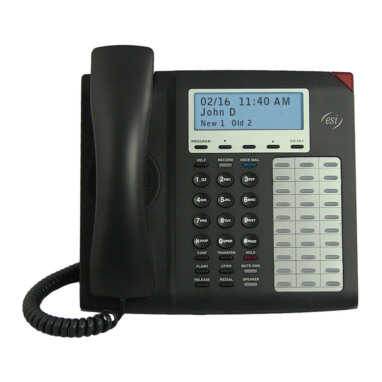
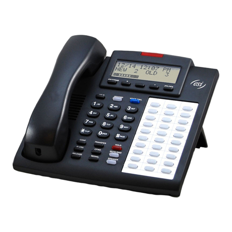
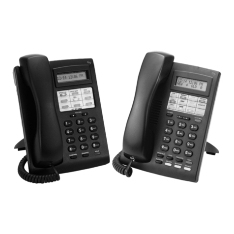
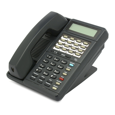
FEATURE PHONES
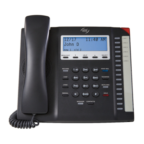
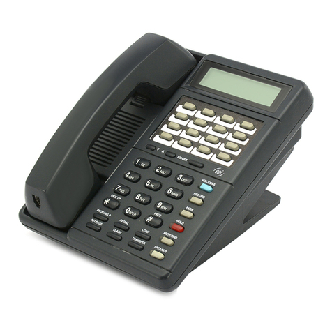
The proprietary feature phones provide advanced call handling
features, an LCD Display, and built-in speaker phone capability.
IVX GENERAL DESCRIPTION 1.1

IVX ADVANCED FEATURES
TOTAL INTEGRATION
IVX provides seamless operation and call processing – no hook-
flash or call progress monitoring required, resulting in the fastest
call processing available.
SIMPLIFIED SET-UP
Installing separate systems require that different programming
techniques and data be interfaced creating potential problem
isolation issues. IVX’s combined functions require NO interface.
IVX’s programming incorporates interactive voice and LCD dis-
play prompts that virtually eliminate ambiguity and guesswork
for the installer, administrator or user.
VERBAL USER GUIDETM
The combination of voice prompts and LCD Display interaction
guides users through station and voice mail feature program-
ming and operation.
VERBAL HELP KEYTM
The HELP Key provides interactive voice and LCD explanations
of user programming requirements and all commonly used
phone features – virtually eliminating the need to consult the
printed user guide.
VOICEMAIL KEY
A unique fixed key that provides for one-stroke immediate inter-
face to the user’s voice mail features. Direct access to a voice
mail box is accomplished by pressing the VOICEMAIL Key from
an idle station. Transferring an outside caller directly to a user’s
mailbox is as simple as pressing the VOICEMAIL Key followed
by the appropriate station key.
LIVE RECORDING
During any conversation, a user can press the REC Key and
record the conversation for later retrieval. Users can record per-
sonal reminders simply by lifting the handset and pressing the
REC key on the phone – and any recording can be further han-
dled the same as any other regular message.
QUICK GROUPSTM
A user can leave a message in several user’s mailboxes without
having to create and manage the traditional group mailboxes.
Simply press the VOICEMAIL Key, press the desired Station
Keys (up to 16) to receive this message and record the message.
IVX
1.2 GENERAL DESCRIPTION

LIVE CALL SCREENING (MESSAGE MONITOR)
Allows a user to handle incoming calls in the same way as a
home answering machine. If the user activates Monitor Mode, a
call presented to the station will ring at the station (including dur-
ing the personal greeting being played to the outside caller).
When the caller begins leaving a message, his or her voice is
also output to the user’s speaker, giving the user the option of
intercepting the call by simply lifting the handset or allowing the
message to be completed to the user’s mailbox.
MESSAGE-ON-HOLD (MOH)
MOH allows for traditional announcement / music to be continu-
ously played to callers while on hold. Three generic messages-
on-hold are permanently stored on disk – or, up to five custom
recordings can easily be downloaded for use.
ON-HOLD DIALING
Because the MOH source is being generated by the system,
DTMF receivers are able to continuously monitor the line –
allowing callers on hold or in ACD queue to dial other options
such as menu selections or the operator.
PERSONAL GREETING REMINDER
Users typically activate this feature to automatically play their
personal greeting the first time the phone is used after extended
absence ensuring removal of outdated greetings. They do have
the option to keep as is, or to change it.
REMOTE SYSTEM SOFTWARE UPDATING
System updates are accomplished via a high-speed, built-in
Modem. System software or built-in voice prompts can be facto-
ry updated via dial-up rather than by costly and time-consuming
EPROM replacement. Dealers can also use the Modem port for
remote real-time monitoring of system activity, debug, or update
of configuration data.
GUEST EXTENSIONS
Employees that work outside of the office can be assigned
Guest Extensions making it appear as if they have a live station
in the office. Example: the normal extensions are numbered
100 to 115. Three outside sales reps are assigned Guest
Extensions 301, 302, and 303. An outside caller dialing 301 at
the main greeting would be forwarded directly to mailbox 301.
Additionally, an inside user can transfer a caller directly to 301's
mailbox by pressing a station key programmed for “extension”
301.
IVX GENERAL DESCRIPTION 1.3
ACD CAPABILITY
Department Groups can be set up to provide sophisticated
Automatic Call Distribution (ACD) features. Calls are presented
to the longest Idle ACD agent or, if all agents are busy, callers
can be held in queue and presented as agents become avail-
able. Possibilities include: Up to 10 agent groups with up to 16
agents in a group.
LCD DISPLAY
Display for users and idle agents indicates number of new and
old messages waiting in voice mail. During retrieval of mes-
sages, the display shows the phone number (*if Caller ID is
active) associated with the message being heard – plus a count-
down display of the message duration. The display shows real
time activity to ACD agents indicating how many calls are hold-
ing and the length of the longest holding call.
CALLER ID
With Caller ID service activated with the service provider, the
name and/or number of the calling party will be displayed on
incoming calls and during call waiting. Additionally, the Caller ID
will be displayed with messages to facilitate automatic callback
to the calling party. Note: Some limitation based on the service
provider and the local dialing patterns may exist.
VISUAL PARK KEYS
These unique keys allow simplified “park & page” to lighted park
keys appearing on all stations. No need for confusing park and
retrieve codes. In addition, a dedicated hold key provides for
exclusive hold.
911 ALERT
This feature provides immediate line access if any station with
line access dials 911 to report an emergency. A message will be
sent via the serial port indicating the start date, time, station
number, and end-time of the 911. Additionally, a warning tone
will sound at the operator station and the LCD display will show
“911 CALL FROM X102 JOHN JAMES".
IVX
1.4 GENERAL DESCRIPTION

STANDARD FEATURES
AUTO ATTENDANT
Auto Attendant is like having an extra staff member on board –
or, it may allow freeing up an existing employee for other duties.
Efficient call handling is assured by up to six menu levels, 40
audiotext branches, directory, Day/Night/Holiday modes, and pri-
mary and secondary answering capability.
However, selected stations (such as lobby phones, top execu-
tives, etc.) can be blocked from receiving calls directly from the
Auto Attendant.
AUTOMATIC MAILBOX CREATION
From the moment an IVX system is up-and-running, mailboxes
are automatically created with generic greeting and forwarding
default values for all users – there’s no waiting for users to
record personal greetings. However, at that point, users are able
to easily create their own custom greetings.
CALL STATISTICS
IVX tracks call activity by Line, Extension, Department, and
System. Summary Reports that are easy to read and interpret
are easily printed by the System Administrator.
CALL FORWARD:BUSY/NOANSWER AND ALL CALLS
The Installer can easily control Call Forward Busy/No Answer for
each station on the system – in both Day and Night Mode. In
addition, individual user control their own Call Forward All Calls.
CALL PICK-UP
Pressing the dedicated PICK-UP Key and a user’s Station Key
or dialed extension number allows a user to intercept a ringing
department or station – minimizing caller aggravation caused by
unanswered ringing.
CALL TRANSFER (LIVE)
Both supervised and blind transfers are accomplished by press-
ing the destination Station Key– or by pressing the TRANS Key
and the destination extension number.
IVX GENERAL DESCRIPTION 1.5

CALL WAITING
A second call (indicated by an audible tone and a display indica-
tion) to an in-use station can be handled by the user much the
same as they do at home with call-waiting...simply press the
FLASH Key to toggle between calls – or hang-up and the other
call will ring. Inside personnel can manually alert someone on
his phone that a call is waiting or someone is waiting in the
lobby, etc.
CLASS OF SERVICE
Service or features programmed for individual stations can be
custom programmed from two levels – the Installer level, or the
Administrator level. The Installer level carries the most authority
and flexibility.
LINE GROUPS
Each outbound Line can be assigned to one of three groups (9,
8, or 7). Icons on a user’s LCD display shows how many lines
exist, whether or not each line is in use, and which line the user
has accessed.
COMMON AUDIBLE
One of the system’s Analog Ports can be designated to provide
common audible (e.g. bell, chime, etc.) ringing to provide simpli-
fied line pick-up from any station.
CONFERENCE / ADD-ON
Up to 12 parties can be in conferences at the same time– up to
four parties in a single conference. However, the originating
extension must remain in the conference.
DAY / NIGHT OPERATION
Day/Night Main Greeting and call processing can be easily pro-
grammed for automatic operation. Alternatively, the operator can
manually change between Day/Night/ Holiday/Automatic with
the press of a key.
DELAYED RINGING
Delayed ringing options allow flexibility in how unanswered
incoming calls are processed. For example, an incoming call
intended for a sales person or department may be progressed to
an administrator – and ultimately to a chime for any available
person to answer. The feature can be programmed on a Line-by-
Line basis to a live operator or for Auto Attendant answer as well
as day/night/answer, or clock/calendar control.
DONOT DISTURB (DND)
This function can be allowed or denied on a station-by-station
basis by the System Administrator. If allowed, a user activates
the feature with the single press of the DND key while the phone
is idle. The DND Key also controls Wrap Time for ACD agents.
IVX
1.6 GENERAL DESCRIPTION

SOFT FEATURE KEYS
These sixteen lighted, programmable keys provide one-touch
transfer to stations, mailboxes, or departments; direct line keys;
speed dial; or other feature access.
EXTERNAL PAGING INTERFACE
CO Line connection or one of two pre-assigned analog ports
also can be used for simplified connection to external overhead
paging equipment.
FAX TRANSFER (AUTOMATIC)
If a FAX tone is detected upon answer by the Auto Attendant,
the call will automatically be transferred to the analog port set as
a FAX extension.
FLASH CONTROL
System programming of the flash duration provides for flexible
usage behind Central Office switches, Centrex, or PBXs.
HANDS-FREE ANSWER
Station users also have the option to program their phone for
hands-free answer (voice announce) for station-to-station calls.
HOLD RECALL
This feature gives flexibility in the amount of time that elapses
between placing a call on Park or on Hold and when that party
is recalled.
LAST NUMBER REDIAL
If an attempt at an outside call is unsuccessful, (eg. a busy sig-
nal), simply press the single RDL Key for a one or more subse-
quent attempts.
LINE PICK-UPMODE
Pressing the PICK-UP Key and 0 to answer a ringing Line or
common audible bell.
LINE QUEUING
Should a call be attempted when all outside lines are busy –
users can elect to be called back and advised by voice
announcement as soon as a line becomes available.
LINE / INTERCOM OFF-HOOK ASSIGNMENT
User control of station off hook preference for access to inter-
com or assigned Line Group dial tone.
IVX GENERAL DESCRIPTION 1.7

DURATION DISPLAY
As a message is played, the LCD display shows its duration
from the beginning of playback and counts down to message
completion.
MESSAGE WAITING INDICATION
The unit will automatically activate the phone’s message light
and provide a real time display on LCD of type and number of
messages.
MODEM (BUILT IN)
A built-in 14.4 kb Modem provides for system update and real
time programming and debug.
MUTE
This fixed key mutes the speaker or handset microphone if
pressed during a call.
NIGHT SERVICE
The system includes both automatic and manual control of
Day/Night Mode.
PAGING
There are three built-in paging zones – and one (1) all-page via
a fixed feature key.
PRIVATE LINE
Lines can be programmed to ring directly to a preset station,
department or mailbox.
SERVICE OBSERVING
Stations designated to observe can be allowed to monitor con-
versations only on specified stations.
SYSTEM SPEED DIAL
Up to 100 names and associated numbers can be stored at a
system wide level.
TOLL RESTRICTION
Based on Allow Local / LD combined with exception tables.
IVX
1.8 GENERAL DESCRIPTION

TECHNICAL SPECIFICATIONS
SYSTEM TYPE:PROPRIETARY EMBEDDED SYSTEM USING DSP TECHNOLOGY.
CABINET:WALL MOUNT 8.5" W X11"H X3" D (6 “ D WITH EXPANSION CABINET).
POWER:90-140 VOLTS AC, 50/60 HZ, 35 WATTS.
CO LINE INTERFACE:UPTO16 ANALOG LOOP START PORTS WITH OPEN LOOP
DETECTION.MEETS FCC, UL, DOC, AND CSA
REQUIREMENTS.
ZAC: 600 OHMS.
REN: LESS THAN 1.0B.
10 KV SURGE T- G ND, (T+R)-GND.
STATION INTERFACE:4 WIRE ANALOG/DIGITAL INTERFACE TO UP TO 32 KEY TELEPHONES.
VOICE STORAGE:17 HOURS AT 64 KB/S SAMPLE RATE.
STORAGE MEDIUM:IDE DISK DRIVE CONTAINING PROPRIETARY ESI FORMAT, PROGRAMS,
CONFIGURATION, AND PROMPTS.
DTMF DETECTION:PASSES MITEL AND BELLCORE DTMF DETECTION TEST TAPES.-25
TO 0DBM, 40 MS / 40MS DETECT.
DTMF GENERATION:TOLERANCE +/-1%. HARMONIC ENERGY IS LESS THAN -16DB
BELOW THE FUNDAMENTAL FREQUENCY.
CROSSTALK:200-3200 HZ:LESS THAN -80 DBM(REF 0DBM).
RS232 INTERFACE:38.4 K B.8DATA BITS, 1 STOP BIT.FULL DUPLEX.
MOH INTERFACE:8 OHM MINI CONNECTOR.
BUILT-INMODEM:14.4 KB.
RFI: FCC PA R T 15, CLASS A. SUSCEPTIBILITY: 30V/M.55-40 MHZ, AM 1000
HZ.
SAFETY:UL1459 AND CSA 225.
ENVIRONMENTAL:OPERATING:0TO 50C, 0 TO 90% RH NON-CONDENSING.
STORAGE: -40 TO 65C.
IVX GENERAL DESCRIPTION 1.9

NOTES:
IVX
1.10 GENERAL DESCRIPTION

IVX
HARDWARE INSTALLATION
IVX hardware configuration consists of the wall
mounted System Cabinet (8.5" W x 11"H x 3"
D ) with an external wall mount transformer
and the IVX Feature Phones. The cabinet
houses the Main Board, slots for two 4 x 8 Port
Cards, and the Memory Module. An expan-
sion cabinet expands the system to 16 x 34.
MAIN BOARD
The main board combines leading-edge hard-
ware components including a 68000 class
Motorola processor and DSP structure along
with proprietary operating system firmware.
The board also provides: a standard RS 232
DB9 serial port for report output and on-site PC connection, a built-in
14.4K baud modem for remote programming/maintenance, and two
analog ports.
MEMORY MODULE
A hard disk drive with proprietary formatting contains all system pro-
gram and configuration data and pre-loaded voice prompts. IVX stores
up to 30 hours of voice at 64Kb/s voice sampling.
PORT CARDS
Port cards provide for configurations in multiples of 4 loop start lines by
8 stations. Each port card has a standard female Amphenol connector
for easy wiring to a standard 66 block.
FEATURE PHONES
The IVX Feature Phone is equipped with speaker phone, 32 character
LCD display, and both fixed and programmable feature keys. Phones
connect to the cabinet via standard 4 wire twisted pairs.
DSS/BLF CONSOLE
The DSS/BLF Console adds 48 additional
Soft Feature Keys to a designated user’s
extension. The console requires a station
port for connection and only one DSS/BLF
Console can be installed per Port Card.
Each console can be paired with any exten-
sion in the system.
IVX HARDWARE INSTALLATION 2.1

FOR YOUR SAFETY
This information complies with the requirements of Underwriter’s
Laboratories and UL Standard 1459.
When using this telephone equipment, always exercise basic
safety precautions in order to minimize the risk of fire, electric
shock or injury to persons. Before proceeding, please read the
following:
The air-flow vents on the IVX case must be free of obstruction
for proper cooling. Similarly, do not install the cabinet in areas of
extreme heat or improper ventilation. Never insert objects of
any kind through the ventilation slots on the system cabinet.
Doing so may result in contact with dangerous voltages – or
cause an electrical short capable of producing fire or shock.
Do not use liquids or aerosols to clean any IVX equipment;
rather, use a cloth that is only slightly damp.
The IVX telephone/voice-mail system contains NO components
that are serviceable by non-dealers or non-manufacturer techni-
cians. All service must be referred to the dealer for further
handling.
CAUTIONS
POWER SUPPLY
Always disconnect the power supply and telephone lines from
the system cabinet before opening the case for service or com-
ponent disassembly or replacement.
Heed all warnings and instructions in documentation or marked
on the cabinet or peripheral equipment.
FUSE
Contact the factory prior to attempting to replace the fuse. The
fuse is located on the mother-board directly next to the power
jack marked with “F1”.
IVX
2.2 HARDWARE INSTALLATION

REGULATORY
REGISTRATION
The CO Line telephone numbers, FCC registration number, and
ringer equivalence of this equipment must be provided to the
telephone company before installation.
FCC PART 15
This equipment has been tested and found to comply with the
limits for a Class A digital device, pursuant to Part 15 of the FCC
Rules. These limits are designed to provide reasonable protec-
tion against harmful interference when the equipment is operat-
ed in a commercial environment. This equipment generates,
and uses, and can radiate radio frequency energy and, if not
installed and used in accordance with the instruction manual,
may cause harmful interference to radio communications.
Operation of this equipment in which case the user will be
required to correct the interference at his/her own expense.
FCC PART 68
Registration Number: 1T1USA-23770-MF-E.
RINGER EQUIVALENCE
REN 0.08
IVX HARDWARE INSTALLATION 2.3

SITE LOCATION
As with most electronic equipment, the environmental consider-
ations for this site need to observe good common sense. Avoid
extreme temperatures and provide a dry, clean, and accessible
area. Do not place the equipment or station runs near high
voltage electrical equipment or electrical lines susceptable
to high voltage surges from air conditioner compressors,
etc.
Locate space in the telephone equipment room which will pro-
vide easy connection to: the 66 blocks (for the CO lines and
stations) and 110VAC power. The location should be no further
than 1,000 feet from the furthest station.
The system and supporting components should be mounted to
a 1/2-inch or greater plywood backboard. A typical installation
layout is shown below.
IVX
2.4 HARDWARE INSTALLATION
Optional Music Source
Power Supply
1st Block
Ext 100 - 107
Analog Ports 191 - 192
Serial Port
CO 1 - 4
2nd Block
Ext 108 - 115
CO 5 - 8
Ground
IVX INTEGRATED VOICE EXCHANGE

MOUNTING THE CABINET
Use three #8 Hex Head screws. Note the position of the three
mounting holes in IVX. Also note that the top keyhole is slightly
off-center to the left.
1) Screw in the top screw to
the back board (at least 1/2
inch thick plywood) leaving
about 1/8th inch clearance
between the screw head and
the plywood.
2) Hang the unit using the
“keyhole” in the back of the
case.
3) Level the unit and install
the bottom two screws.
Attach the Power Transformer
to the wall allowing sufficient
length in both cords to reach the power connector on the upper
right side of the cabinet and to reach a standard 110v outlet.
Do not connect power until all hardware connections have
been made.
66 BLOCK WIRING DIAGRAM
Connect a standard male 50-pin Amphenol cable to each port
card female connector located on the bottom-right side of the
cabinet. The connector closest to the wall is the first card. Its 66
Block connects to the first 8 Stations, the 2 Analog Ports, the
Optional Serial Data Port, and the first 4 CO Lines. The second
Port Card connects to the second 8 Stations and the second 4
CO Lines. See Figure 1.
The Expansion Cabinet is required to add the third and fourth
Port Cards.
IVX HARDWARE INSTALLATION 2.5

1st Port Card Additional Port Cards
Card
TERM WIRE COLOR SIGNAL RJ11PORT SIGNAL RJ11 2 3 4
1 White-Blue Tip Green Station 100 Tip Green 108 116 124
2 Blue-White Ring Red (Oper) Ring Red
3 White-Orange Data+ Black Data+ Black
4 Orange-White Data- Yellow Data- Yellow
5 White-Green Tip Green Station 101 Tip Green 109 117 125
6 Green-White Ring Red Ring Red
7 White-Brown Data+ Black Data+ Black
8 Brown-White Data- Yellow Data- Yellow
9 White-Slate Tip Green Station 102 Tip Green 110 118 126
10 Slate-White Ring Red Ring Red
11 Red-Blue Data+ Black Data+ Black
12 Blue-Red Data- Yellow Data- Yellow
13 Red-Orange Tip Green Station 103 Tip Green 111 119 127
14 Orange-Red Ring Red Ring Red
15 Red-Green Data+ Black Data+ Black
16 Green-Red Data- Yellow Data- Yellow
17 Red-Brown Tip Green Station 104 Tip Green 112 120 128
18 Brown-Red Ring Red Ring Red
19 Red-Slate Data+ Black Data+ Black
20 Slate-Red Data- Yellow Data- Yellow
21 Black-Blue Tip Green Station 105 Tip Green 113 121 129
22 Blue-Black Ring Red Ring Red
23 Black-Orange Data+ Black Data+ Black
24 Orange-Black Data- Yellow Data- Yellow
25 Black-Green Tip Green Station 106 Tip Green 114 122 130
26 Green-Black Ring Red Ring Red
27 Black-Brown Data+ Black Data+ Black
28 Brown-Black Data- Yellow Data- Yellow
29 Black-Slate Tip Green Station 107 Tip Green 115 123 131
30 Slate-Black Ring Red Ring Red
31 Yellow-Blue Data+ Black Data+ Black
32 Blue-Yellow Data- Yellow Data- Yellow
33 Yellow-Orange Tip Green Analog Port 191
34 Orange-Yellow Ring Red
35 Yellow-Green Tip Green Analog Port 192
36 Green-Yellow Ring Red
37 Yellow-Brown CTS Serial Port
38 Brown-Yellow RTS
39 Yellow-Slate TXD
40 Slate-Yellow RXD
41 Violet-Blue GND
42 Blue-Violet GND CO
43 Violet-Orange Tip Green CO 1 Tip Green 5 9 13
44 Orange-Violet Ring Red Ring Red
45 Violet-Green Tip Green CO 2 Tip Green 6 10 14
46 Green-Violet Ring Red Ring Red
47 Violet-Brown Tip Green CO 3 Tip Green 7 11 15
48 Brown-Violet Ring Red Ring Red
49 Violet-Slate Tip Green CO 4 Tip Green 8 12 16
50 Slate-Violet Ring Red Ring Red
FIGURE 1 66 BLOCK WIRING DIAGRAM
Other manuals for ORIGINAL IVX
2
Table of contents
Other ESI Telephone manuals

ESI
ESI 30D Business Phone User manual

ESI
ESI ESI Phone Specification sheet

ESI
ESI 12-Key Feature Phone User manual

ESI
ESI IVX 20 User manual

ESI
ESI IVX 20 Plus Owner's manual

ESI
ESI 60 Business Phone User manual

ESI
ESI IVX 128 User manual

ESI
ESI 45SIP User manual

ESI
ESI 50L User manual

ESI
ESI ePhone3 V2 User manual

ESI
ESI IVX C-Class User manual

ESI
ESI 55 User manual

ESI
ESI 48-Key Feature Phone User manual

ESI
ESI IVX S-Class Use and care manual

ESI
ESI IVX 20 User manual

ESI
ESI 24-Key Feature Phone User manual

ESI
ESI IVX S-Class User manual

ESI
ESI ePhone8 User manual

ESI
ESI eSIP Evolution Series User manual

ESI
ESI ivx e-class series Use and care manual