Esu SwitchPilot 3 User manual

Instruction manual
2. Edition, May 2021
P/N 01721-24983
From Decoder Firmware 3.0.9
51832 SwitchPilot 3 Servo
SwitchPilot 3 Servo
SWitch Pilot

2
1. Declaration of conformity....................................... 3
2. WEEE-Declaration .................................................... 4
3. Important Notes....................................................... 4
4. Features ..........................................................................5
4.1. General Features...........................................................5
4.2. Technical Data...............................................................5
4.3. Scope of delivery...........................................................5
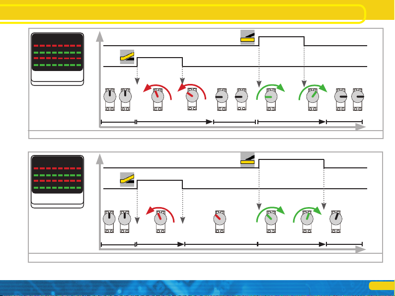
4.4. Operating modes..........................................................6
4.4.1. Digital mode..............................................................6
4.4.2. Proportional mode ...................................................6
4.5. Servo types ...................................................................8
4.5.1. Analog servos ............................................................8
4.5.2. Digital servos .............................................................8
4.5.3. ESU servo drive .........................................................8
5. Connection to the digital system ........................... 9
5.1. Terminals ......................................................................9
5.2. Power supply by the digital system..............................10
5.3. External power supply ................................................10
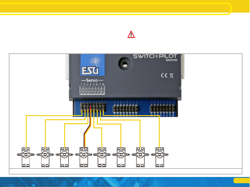
5.4. Wiring the outputs .....................................................11
5.4.1. Servo connection ....................................................11
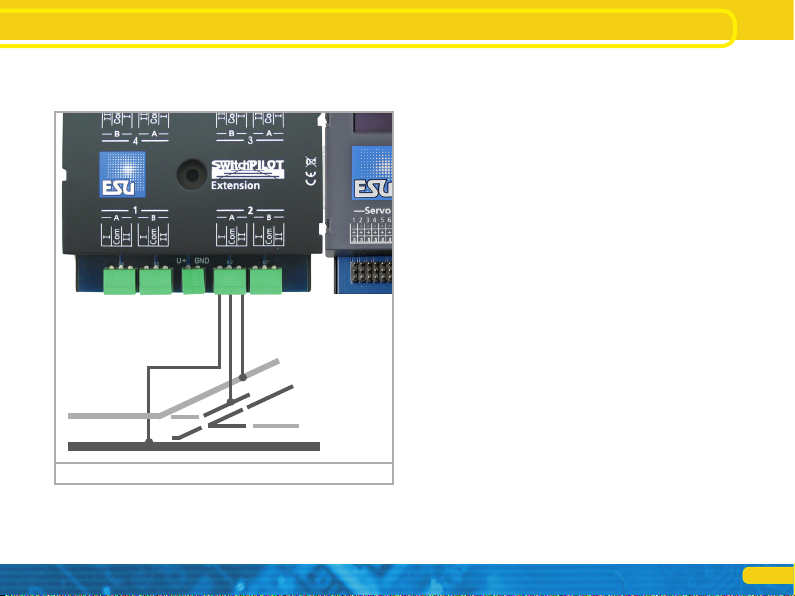
5.5. Connecting the SwitchPilot Extension .........................12
5.5.1. Relay outputs...........................................................12
5.5.2. Turnout frog polarization .........................................13
6. Configuration with OLED...................................... 14
6.1. Relationship accessory addresses / turnout numbers ...14
6.1.1. Assigning turnout numbers......................................15
6.2. Introduction to the operating structure.......................16
6.3. Address mode for ROCO® command stations ............17
6.4. Configuring outputs ...................................................17
6.4.1. Servo position und mode .........................................17
6.4.2. Servo speed and relay response time........................18
6.4.3. Servo seesaw effect (“Bouncing”)............................18
6.5. Servo pulse configuration............................................18
6.6. Function Mapping.......................................................19
Content
6.7. Status information ......................................................20
6.7.1. Display software version & track voltage ..................20
6.7.2. Displaying the status of the outputs.........................20
7. Configuration with LokProgrammer.................... 21
8. Configuration POM................................................ 22
8.1. Connection to the digital system.................................22
8.2. Reading and writing CVs with POM ...........................22
9. Configuration with the programming track........ 23
9.1. Connection to the digital system.................................23
9.2. Read & Write CVs .......................................................23
10. Learning turnout numbers from command station..23
11. RailCom® ............................................................. 24
11.1. RailCom® Configuration .........................................24
12. Direct switching with the inputs for push buttons... 24
13. Reset to factory default (decoder reset)............ 25
13.1. With the programming button..................................25
13.2. With DCC systems ....................................................25
13.3. With the display........................................................25
14. Support ................................................................. 25
15. Menu references .................................................. 26
16. Solenoid address & turnout numbers ................ 31
17. List of all supported CVs...................................... 33
18. Change history..................................................... 38
19. Warranty certificate............................................. 39

3
Declaration of Conformity
1. Declaration of conformity
The manufacturer, ESU electronic solutions ulm GmbH & Co. KG,
Edisonallee 29, D-89231 Neu-Ulm, hereby declares under its sole
responsibility that the product
Product name: SwitchPilot 3 Servo
Type: 51832
complies with all relevant provisions of the Electromagnetic Com-
patibility Directive (2004/108/EC). The following harmonised stan-
dards have been applied:
EN 55014-1:2006 + A1:2009: Electromagnetic compatibility -
Requirements for household appliances, power tools and similar
electrical appliances - Part 1: Interference emission
EN 55014-2:1997 + A1:2001 + A2:2008: Electromagnetic compa-
tibility - Requirements for household appliances, power tools and
similar electrical appliances - Part 2: Immunity.
Copyright 1998 - 2021 by ESU electronic solutions ulm GmbH & Co KG. Irrtum, Änderungen die dem technischen Fortschritt dienen, Liefermöglichkeiten und alle sonstigen
Rechte vorbehalten. Elektrische und mechanische Maßangaben sowie Abbildungen ohne Gewähr. Jede Haftung für Schäden und Folgeschäden durch nicht bestimmungs-
gemäßen Gebrauch, Nichtbeachtung dieser Anleitung, eigenmächtige Umbauten u. ä. ist ausgeschlossen. Nicht geeignet für Kinder unter 14 Jahren. Bei unsachgemäßem
Gebrauch besteht Verletzungsgefahr.
Märklin® und mfx® sind eingetragene Warenzeichen der Firma Gebr. Märklin® und Cie. GmbH, Göppingen. RailCom® ist ein eingetragenes Warenzeichen der Firma
Lenz® Elektronik GmbH, Gießen.
Alle anderen Warenzeichen sind Eigentum ihrer jeweiligen Rechteinhaber.
ESU electronic solutions ulm GmbH & Co. KG entwickelt entsprechend seiner Politik die Produkte ständig weiter. ESU behält sich deshalb das Recht vor, ohne vorherige
Ankündigung an jedem der in der Dokumentation beschriebenen Produkte Änderungen und Verbesserungen vorzunehmen.
Vervielfältigungen und Reproduktionen dieser Dokumentation in jeglicher Form bedürfen der vorherigen schriftlichen Genehmigung durch ESU.

4
WEEE Declaration Features
2. WEEE-Declaration
Disposal of old electrical and electronic equipment (valid in the
European Union and other European countries with separate coll-
ection system).
This symbol on the product of the packaging or in
the documentation means that this product must
not be treated as household waste. Instead, this
product is to be taken to the appropriate disposal
point for recycling electrical and electronic equip-
ment. If the product is disposed of correctly, you
help to prevent negative environmental influences and damage
to health that could be caused by improper disposal. Recycling
material will preserve our natural resources. For more information
about recycling this product, please contact your local citizens‘
office, household waste collection service or the store where you
purchased this product.
3. Important Notes
Congratulations on your purchase of an ESU SwitchPilot 3 Servo
decoder. This manual wants to introduce you step by step to the
possibilities of the decoder. Therefore, a request:
Please carefully work through this manual prior to commissioning.
Although all SwitchPilot decoders are very robust, a wrong con-
nection could destroy the device. If in doubt, avoid „expensive”
experiments.
•The SwitchPilot is intended exclusively for use with electric model
railway layouts. It may only be operated with the components de-
scribed in this manual. Any use other than that described in this
manual is not permitted.
•All connection work may only be carried out when the operating
voltage is switched off.
•The power supply units must be protected in such a way that in
the event of a short circuit, there is no risk of a cable fire. Use only
commercially available model train transformers manufactured ac-
cording to the VDE/EN standards, bearing the CE mark.
•Never operate the SwitchPilot unattended. The SwitchPilot is not
a (children’s) toy.
•Follow the principles of this manual when connecting the external
components. The use of other circuits may cause damage to the
decoder.
•The SwitchPilot is not waterproof: outdoor use is not intended and
is done at your own risk.
•Do not attempt to open your SwitchPilot module. Improper treat-
ment can destroy it.

5
Features
4. Features
ESU SwitchPilot 3 Servo decoders are optimized for stationary use
on your model train layout and were developed to control up to
eight RC servo drives.
4.1. General Features
The SwitchPilot 3 Servo has eight outputs for controlling RC servo
drives. He can control these drives so precisely that, in addition to
switching points, any other slow movement can be controlled .
The SwitchPilot 3 Servo has built-in switch-on impulse suppression
to eliminate or reduce the system-related „jerking” of RC servos
when the supply voltage is applied. Furthermore, the power sup-
ply to the servo can be interrupted to prevent some inexpensive
servos from “humming”.
The SwitchPilot 3 Servo can receive its power directly from the
digital system or an external DC or AC power supply.
SwitchPilot 3 Servo supports multi-protocol operation and can
be used with central units supporting the Märklin® Motorola®
system (e.g.: 6021, Central Station® or Mobile Station®) as well
as DCC enabled command stations. Configuration can be carried
out on the main (POM – Programming on the Main) and the pro-
gramming track. Thanks to RailCom®, CVs can also be read out.
Operation with the Roco® Lokmaus 2 is not possible: The Lok-
maus 2 sends only DCC locomotive commands instead of the re-
quired accessory commands.
As a special feature, the SwitchPilot 3 Servo can be used entirely
without a digital center: if desired, up to 16 buttons can be con-
nected for direct switching of the servos.
For simplifying the rather cumbersome configuration of accesso-
ry decoders, the SwitchPilot 3 Servo has an innovative operating
concept consisting of a 4-line, illuminated OLED display and three
input buttons. All settings can be checked directly on the decoder
at any time with the help of the display and changed, if so desired.
„Programming” with the help of your command station is not
required. It cannot get any easier.
4.2. Technical Data
SwitchPilot 3 Servo
Input voltage 12V - 20V DC power supply
12V - 16V AC power supply
Digital track voltage
Outputs 8 Servo outputs for RC servos
Pulse lengths from 1.0ms to 2.0ms
Output power Complete module 2A
Feedback inputs Non existent.
Operating modes DCC „Accessory Decoder” with Rail-
Com® (addressing according to RCN-213
or ROCO®). Turnout numbers 1 - 2048.
Märklin® Motorola®. Turnout numbers
1 - 256. K83 and K84 operating modes.
Direct triggering of the servos possible by
using buttons.
Configuration 0.91“ OLED display with 3 buttons
Dimensions 86mm x 86mm x 25mm
4.3. Scope of delivery
The SwitchPilot 3 Servo comes with a removable terminal block (1x
4-pin for the track connection. Under part number 51800.SP.01 a
pack of replacement terminal blocks is available from ESU.

6
4.4. Operating modes
You may connect RC servos directly to any of the 8 outputs of the
SwitchPilot 3 Servo. Contrary to geared motors, servo motors are
intelligent actuators with integral intelligence that can self-reliantly
move to the desired position and remain there. During this process
they apply different power and angular frequency. If any resistance
(force) is applied against the lever, then the servo will be regulated
in order to always reach the pre-determined angle.
The required position is determined via an impulse wire (orange
in case of Graupner® servos, otherwise white). A continuous po-
wer supply (4.8V – 6V) completes the interface. Every 20 – 25ms
the servo expects to receive a positive impulse on the pulse wire
with a duration of 1.0ms to 2.0ms. The duration of the impulse is
directly proportional to the desired position. Fig. 1 illustrates the
correlation.
There are servos of many different types and design sizes. They
also differ in their gear reduction ratio and the adjustment travel.
Thus, there are, for instance, servos for adjusting sails that make
several turns.
Operating modes
There are many different types of servos on the market and not all
of them are suitable for use with model trains.
Never try to move the turning lever manually! The gears of the
servo may be damaged!
In general, there are two types of operating modes for servos.
They can be individually set for each output.
4.4.1. Digital mode
In digital mode and subject to the settings of the control panel
every servo can move to two end positions “A” and “B”. With the
SwitchPilot 3 Servo you can adjust both end positions as well as
the speed at which the servo moves from “A” to “B”.
In digital mode every servo will always stop at one of the two end
positions “A” or “B”, never in between.
As an option one can determine if the servo pulse should be con-
tinuously switched on or should only be active during movement.
This is helpful when operating analogue servos. Furthermore, one
can determine if the supply voltage should be turned off once the
servo has reached the desired end position.
The digital mode is perfectly suitable for controlling turnouts or
signals that should always remain in a fixed position.
4.4.2. Proportional mode
For the first time the proportional mode is instituted with the
SwichPilot 3 Servo and replaces the previously known positions
“C” and “D” of servos.
In proportional mode the servo can move and stop at any position
between the end position “A” and “B”. The servo moves as long
as the control panel transmits a command. Once you release the
button, the servo stops. Thus, you can stop the servo at any desi-
red position. The speed of movement is adjustable.
The proportional mode is ideally suited for applications like water
standpipes for steam locomotives or gates of engine sheds. In fact,
for any other application that requires in between positions.
Figure 1: Impulse control of RC servos
2.50ms
2.00ms
1.50ms
1.00ms
0.00ms
2.50ms
2.00ms
1.50ms
1.00ms
0.00ms
2.50ms
2.00ms
1.50ms
1.00ms
0.00ms
1.50 ms: neutral 1.00 ms: 0° (left) 2.00 ms: 180° (right)

7
Operating modes
Figure 2: Digital mode
keyboard
1 2 3 4 5 6 7 8
9 10 11 12 13 14 15 16
time
on
off
RED
ON
RED
OFF
GREEN
ON
GREEN
OFF
Turns to „A“ „Speed A“ Pos „A“ Turns to „B“ „Speed B“ Pos „B“
Figure 3: Proportional mode
keyboard
1 2 3 4 5 6 7 8
9 10 11 12 13 14 15 16
time
on
off
RED
ON
RED
OFF
GREEN
ON
GREEN
OFF
Turns to „A“ Stands still Turns to „B“ Stands still

8
4.5. Servo types
Even if they look the same, technically different servos are availab-
le on the market. It is important that you configure the SwitchPilot
3 servo appropriately to avoid problems.
4.5.1. Analog servos
With a classic servo, the motor is only energized when a pulse
signal is present. Without a signal, it follows the mechanical forces
on the lever. If these servos „hum” in the rest position, you can
ensure silence by switching off the pulse. However, it is possible
that the servos “twitch” when the pulse is switched on again.
For analog servos set the impulse configuration in CV 43 to 3.
4.5.2. Digital servos
With the digital servo, a microcontroller inside the servo ensures
that the motor is readjusted even if there is no external impulse.
These servos also tend to „hum” when not in use, because the
external actuating forces are through the motor should be com-
pensated. A digital servo only comes to rest when the voltage is
interrupted from the outside. The disadvantage of this method,
however, is that the servo can twitch in an uncontrolled manner
when the voltage is reapplied.
Set the impulse configuration CV 43 to 4 for digital servos.
4.5.3. ESU servo drive
With the servo drives (51804 with plastic gears, 51805 with metal
gears), ESU offers particularly small drives that have been specially
optimized for use in model railways. Both are equipped with a
microcontroller whose special programming reliably prevents hum
in the end position.
In addition, the drive is supplied with all the accessories necessary
for the point control and saves you the hassle of searching for
small parts.
Servo Types

9
Figure 4: Terminals of the SwitchPilot 3 Servo
Connection to the digital system
g)
f)
e) c) b)
a) h) h)
5. Connection to the digital system
We recommend that you first configure the SwitchPilot 3 Servo
decoder completely and then install it on the layout.
5.1. Terminals
Fig. 4 shows the SwitchPilot 3 Servo with all terminals.
a) This pin header block is used to connect 8 RC servo drives (e.g.
ESU, Futaba®, etc.) and forms the outputs 1-8 of the Switch-
Pilot 3 servo.
b) The power supply of the SwitchPilot 3 including all connected
loads is realized vie the Terminals Pw A and Pw B. You can eit-
her use the track voltage or use an external power supply. We
recommend an external power supply, particularly for larger
layouts, because then the energy for powering the drives does
not add to the load for the command station or booster.
c) Connect the Terminals Trk A and Trk B to the track output of
the command station (or booster) that controls the SwitchPilot
3 Servo.
e) Input unit. The three buttons PROG/OK as well as (+) and (-)
serve to configure the decoder, as explained in chapter 6.
f) The display shows all settings of the decoder including turnout
address and status of the outputs. After a few seconds, the
screen saver displays the supply voltage.
g) Extension socket for the SwitchPilot Extension relay module.
h) These pin header blocks are used to connect 2 x 4 external
switch buttons in order to be able to specify the servo positions
directly without a digital center. Chapter 12 provides more in-
formation.
g)

10
Connection to the digital system
5.2. Power supply by the digital system
For smaller layouts with only a few electric loads turned on at the
same time, the SwitchPilot 3 can be supplied directly from the
command station or booster. The terminals Pw A and Pw B are
connected parallel to the terminals Trk A and Trk B.
This wiring scheme must be used if you want to configure the
SwitchPilot 3 Servo on the programming track of your command
station. For more information, see Chapter 9.
5.3. External power supply
For larger layouts with many electric loads, we recommend the
use of an external power supply. DC and AC power supplies are
suitable with the specifications described in chapter 4.2. We re-
commend the use of a stabilized DC power supply with at least
14V DC at least 3A output power (e.g.: ESU part number 50119).
This type of wiring cannot be used for programming on the pro-
gramming track. In this case, a temporary connection must be
established as shown in chapter 5.2.
B 0
Main track exit
min. 18V
B 0
Main track exit
approx.
14V
Stabilized DC
power supply
recommended
Figure 5: Supply from the digital system Figure 6: Separate (external) power supply

11
Wiring the outputs
5.4. Wiring the outputs
5.4.1. Servo connection
All commercially available RC model building servos with a three-
pole connection and positive pulse can be used. The SwitchPilot
3 Servo supplies them with 5V. Figure 7 shows the general con-
nection.
Figure 7: Servo connection
Simply plug the connection cable of the servo into the correspon-
ding socket on the SwitchPilot (servo). The pulse output is usually
the white or orange wire.
Note the connection drawing on the housing of the SwitchPilot
3 Servo. An incorrect connection can destroy the servo or the
SwitchPilot!

12
Wiring the outputs
5.5. Connecting the SwitchPilot Extension
Up to two SwitchPilot Extension Modules can be docked to the
side of the SwitchPilot 3 Servo. To do this, press the modules with
the 8-pin plugs against each other until the latches on the plugs
engage. The internal logic and the relay coils of the SwitchPilot
extension module are also supplied by the SwitchPilot 3 servo.
The SwitchPilot Extension module on the left is responsible for
outputs 1 to 4, the SwitchPilot Extension module on the right is
responsible for outputs 5 to 8.
5.5.1. Relay outputs
Fig. 8 shows the connections:
a) The outputs 1 to 4 are connected to relay outputs A and B,
which are activated jointly (2x change-over contacts, bistable).
Each relay output corresponds to the corresponding transistor
output of the SwitchPilot 3. If the output Out A of the Switch-
Pilot 3 is active, the terminals Iand COM of the relay output
are also active. If the output Out B on the SwitchPilot 3 is
active, terminals II and COM are also active.
b) Terminals for ground and „U+” (rectified track voltage, sup-
plied by SwitchPilot 3) for powering DC turnout motors.
Figure 8: SwitchPilot Servo with two mounted SwitchPilot Extension modules
a) a) b) a) a)
a) a) b) a) a)
III
Com
For outputs 5 bis 8For outputs 1 bis 4

13
5.5.2. Turnout frog polarization
With the SwitchPilot Exension module, turnout frogs can be po-
larized very easily.
Wiring the outputs
Figure 9: Polarization with SwitchPilot Extension

14
Each SwitchPilot 3 Servo can be assigned two 4-series group: this
is the so-called accessory address.
The solenoid address 1 is stored internally in CV 1 and CV 9. The
solenoid address 2 is stored internally in CV 35 and CV 36. The
calculation of the turnout numbers from the values stored in the
two CVs is regulated in the RCN-213.
The table in chapter 16 lists turnout numbers and corresponding
accessory addresses. Only the first 256 turnouts are available
when operating with Motorola® central units.
It is not possible to assign turnout numbers outside the group-of-4
limits to a SwitchPilot 3 Servo. For example. it would not be pos-
sible to assign turnout numbers 4, 5, 6 and 7, as these go beyond
the limit of the accessory address groups. Please keep this in mind
when assigning turnout numbers.
The two output groups 1 to 4 and 5 to 8 can be selected inde-
pendently.
Due to a weakness in the DCC standard prior to the creation of
the RCN-213, some command stations (especially ROCO® Multi-
maus or Z21) calculate the turnout numbers differently. In this case
please take note of chapter 6.3.
Configuration with OLED
6. Configuration with OLED
The programming of accessory decoders was usually very cum-
bersome in the past. CV programming with the help of the hand-
held throttle often failed due to the missing programming modes
(e.g.: only very few command stations and/or throttles respectively
central units support „POM for accessory decoders”) or forgotten
addresses of decoders installed on the layout. Even assigning the
decoder address presented many model railway enthusiasts with
major obstacles. Reading the currently assigned decoder address is
also quite cumbersome and causes a lot of displeasure.
To avoid such problems, the SwitchPilot 3 Servo is the first acces-
sory decoder on the market working with an innovative operating
concept. It consists of an illuminated multi-line OLED display and a
3-button input unit. This allows programming all (!) settings of the
SwitchPilot 3 Servo in plain text directly on the decoder, without
the need of external programming devices or cumbersome CV
programming. In addition, the display shows the currently assig-
ned turnout numbers at any time and can even accurately display
the supply voltage (respectively track voltage). A screen saver pre-
vents the OLED display from burning in.
6.1. Relationship between accessory addresses and turnout
numbers
For addressing the outputs of the SwitchPilot 3 Servo decoder
with the command station, so-called turnout numbers must be
assigned to them. The number of turnout numbers is limited and
depends on the digital system:
Motorola®: Turnout numbers 0001 to 0256
DCC: Turnout numbers 0001 to 2048
(ROCO command stations 0001 to 2040).
The turnout numbers are arranged into four groups. The first
group comprises turnout numbers 1,2,3,4, the second group the
turnout numbers 5,6,7,8, the third group the turnout numbers
9,10,11,12, and so forth.
Assigning turnout numbers

15
Assigning turnout numbers
6.1.1. Assigning turnout numbers
The 8 servos of the SwitchPilot 3 Servo decoder react ex works
to the turnout numbers 0001 to 0004 and 0005 to 0008. The
turnout numbers can easily be changed directly on the SwitchPilot
3 Servo.
a) Check whether the display shows the screen saver (lettering
„SP” and the supply voltage):
b) In this case, press the „PROG/OK” button only (!) briefly. Now
the SwitchPilot 3 Servo should display its current turnout num-
bers directly in plain text:
c) Press the „PROG/OK” button. The turnout numbers 1-4 should
now flash (inverse).
d) Press the button (+) or (-) to select the desired turnout numbers
for output 1 to 4. The currently selected turnout numbers are
displayed flashing.
e) Press the „PROG/OK” button again to confirm the turnout
numbers for outputs 1 to 4. The display no longer flashes, but
the one for outputs 5 to 8.
SPS»17.3V
ADDRESS
Switch 1-4: 0001-0004
Switch 5-8: 0005-0008
ADDRESS
Switch 1-4: 0001-0004
Switch 5-8: 0005-0008
ADDRESS
Switch 1-4: 0009-0012
Switch 5-8: 0005-0008
f) Press the button (+) or (-) to select the desired turnout numbers
for output 5 to 8. The currently selected turnout numbers are
displayed flashing.
g) Press the „PROG/OK” button again to confirm the turnout
numbers for outputs 5 to 8. The display no longer flashes.
Finished! Without programming or cumbersome handling on the
handheld throttle or command station.
ADDRESS
Switch 1-4: 0009-0012
Switch 5-8: 0013-0016

16
SERVO 1 POSITION
Pos A : 10
Pos B : 40
Mode : Digital
Introduction to the operating structure
6.2. Introduction to the operating structure
The configuration with the aid of the OLED display and the 3-but-
ton input unit enables you to set all parameters of the SwitchPilot
3 Servo decoder.
All properties are arranged in so-called „panels”. A panel fills in
all four lines of the display. The first line displays the name of the
panel, and rows two to four display a maximum of three different
setting options. With the help of the „+” and „-” buttons you can
scroll between the individual panels.
a) Name of the panel
b) Name of setting option 1
c) Value of the setting option 1
d) Name of setting option 2
e) Value of the setting option 2
f) Name of the setting option 3
g) Value of the setting option 3
Figure 10: Control elements of the SwitchPilot 3 Servo
ADDRESS
Switch 1-4: 0001-0004
Switch 5-8: 0005-0008
ADDRESS
Switch 1-4: 0001-0004
Switch 5-8: 0005-0008
ADDRESS MODE
Mode : RCN-213
OUTPUT STATE
1 2 3 4 5 6 7 8
CMD .».»».».»..».»».
END .».»..».»....»».
SERVO 1 POSITION
Pos A : 24
Pos B : 40
Mode : Digital
a)
c)
a)
b)
d)
f)
e)
g)
SERVO 1 POSITION
Pos A : 24
Pos B : 40
Mode : Digital
PROG/OK
SERVO 1 POSITION
Pos A : 10
Pos B : 40
Mode : Digital
PROG/OK
SERVO 1 POSITION
Pos A : 10
Pos B : 40
Mode : Digital
PROG/OK
PROG/OK
Configuring outputs

17
Introduction to the operating structure
•If you want to change a setting option of the currently selected
panel, press the PROG/OK button once. The setting option 1 of
the screen will now flash as a sign that it can be changed.
•For changing the respective setting use the (+) and (-) buttons.
Press the button until the display shows the desired value. The de-
coder immediately applies the changes so you can see immediately
what is happening.
•Confirm your entry with PROG/OK. After that, the next setting
option will flash as a sign that it can now be changed.
If you do not want to change a setting option, but only want to
proceed to the next one, just press the PROG/OK button. Then
the current value is not changed.
•After you have changed the last of the three setting options re-
spectively confirmed them by pressing PROG/OK, nothing will
flash. You are now back in the display mode of the panel and can
now either make changes to other setting options of the panel
by pressing PROG/OK again or select another panel with the (+)
and (-) buttons.
For a list of all possible panels and their setting options, see Chap-
ter 15.
6.3. Address mode for ROCO® command stations
As already mentioned in Chapter 6.1, ROCO® command stations
(specially the multiMaus, but also the Z21 in the standard setting)
use a different computation method to calculate the turnout num-
bers from the accessory addresses. Set the decoder to “ROCO” to
ensure that the SwitchPilot 3 handles instructions from ROCO®
command stations correctly.
To do this, select „Mode” in the „ADDRESS MODE” panel, and
then select the calculation method „ROCO”.
Configuring outputs
6.4. Configuring outputs
The properties of each output can be configured individually.
Three panels are provided for each exit in order to be able to show
the total of 9 options.
6.4.1. Servo position und mode
“Pos. A” defines the end position (the angle) of the servo in po-
sition “A”. The precise value depends on the type of servo and
its mounting situation. This value can only be determined expe-
rimentally.
As soon as you change the value with (+) or (-), the servo connec-
ted to this output will move to the new value immediately. Thus,
you may test the effect of any adjustment right away.
“Pos. B” defines the end position (the angle) of the servo in po-
sition “B”. The precise value depends on the type of servo and
its mounting situation. This value can only be determined expe-
rimentally.
As soon as you change the value with (+) or (-), the servo connec-
ted to this output will move to the new value immediately. Thus,
you may test the effect of any adjustment right away.
“Mode” enables you to set the desired mode:
• “Digital” configures the digital mode as per chapter 4.4.1
•“Proportional” configures the proportional mode as per chapter
4.4.2.
SERVO 1 POSITION
Pos A : 24
Pos B : 40
Mode : Digital

18
Configuring outputs
6.4.2. Servo speed and relay response time
You may adjust the speed of movement for each output separate-
ly. Thus, prototypically slow movements can be realised.
Large values may possibly lead to such a slow speed that the me-
chanics of the servo may start to stall or move irregularly, thus
causing the servo to fail in performing a smooth turn. In that case,
please reduce the values or try to obtain another servo better sui-
table for extremely low speeds. Of course, the Switch Pilot 3 Servo
cannot influence the mechanical properties of the servo.
“Speed A” determines the duration of movement with which po-
sition “A” will be reached.
As soon as you change the value with (+) or (-), the servo con-
nected to this output will continuously move between positions
“A” and “B”. This enables you to observe the effects of any value
changes right away.
“Speed B” determines the duration of movement with which po-
sition “B” will be reached.
With option “SPE REL” one determines the point in time when the
corresponding relay wired to the optionally connected SwitchPilot
Extension module will be activated. Normally these relays switch
immediately after receiving a control command. However, this may
lead to a short circuit if the frog of a turnout is connected. This
is due to the fact, that the points of the turnout are not moved
immediately but are still connected to the stock rail for a moment.
One can adjust the response time for activating the relay once
the servo has reached the centre position between the two end
positions “A” and “B”. The precise switching time depends on the
desired regulating time of the servo.
Delay On The relay is activated halfway through the move-
ment between “A” and “B”.
Delay Off The relay responds immediately.
6.4.3. Servo seesaw effect (“Bouncing”)
If desired, every servo can facilitate a seesaw movement for si-
mulating semaphore signals. One can choose at which end posi-
tions the effect should be triggered as well as how often and how
strong this seesaw motion should be.
“Bouncing” determines if and where this effect should be acti-
vated:
Disabled No bouncing effect (factory default).
Pos A Bouncing after reaching position “A”.
Pos B Bouncing after reaching position “B”.
Pos A + B Bouncing after reaching either position.
Provided the bouncing function has been selected, you may adjust
the following parameters:
“Bounces” determines the number of bouncing movements.
“Strength” defines how far the servo should bounce back.
6.5. Servo pulse configuration
For avoiding any effects such as buzzing of analogue servos or jer-
king at switch-on of digital servos you may adjust the servo pulses
of your SwitchPilot 3 Servo. The power supply for the servo may
also be turned off if required.
To assure the correct functionality of your servos, it is paramount
that all parameters are adjusted correctly. Buzzing servos may be
overheated and could possibly be damaged or destroyed!
Function mapping
SERVO 1 SPEED
Speed A : 40
Speed B : 40
SPE REL : Delay On
SERVO 1 BOUNCING
Bouncing: Pos A+B
Bounces : 0
Strength: 0
SERVO CONTROL
Imp On : Always
Imp Off : Never
PWR : Always

19
Configuring outputs Function mapping
There are three options for adjustment:
“Imp On” determines when a servo pulse shall be generated.
Always Once the power supply for the SwitchPilot 3 Ser-
vo is turned on, the servo impulse is generated
immediately. Recommended for digital as well as
ESU servos.
On CMD A servo impulse is only generated once a swit-
ching command has been transmitted to the
servo. Recommended for analogue servos for
avoiding buzzing after having reached the end
position.
“Imp Off” determines the time after which the servo impulse will
be switched off again.
Never After activating the servo impulse, it will be con-
tinually transmitted. Recommended for digital as
well as ESU servos.
Timeout The servo impulse will be turned off about one
second after reaching the end position (“A” or
“B”). Recommended for analogue servos to avo-
id buzzing after reaching the end position.
“PWR” determines how the power supply for the servo is to be
set up.
Always The power supply is never switched off. Recom-
mended for analogue as well as ESU servos.
On Move The power supply is turned off once the servo
has reached its end position. Recommended for
digital servos for avoiding buzzing after reaching
the end position.
Subject to design, construction and configuration of the servo
other combinations of the above three options are feasible. If in
doubt, simply try it out for reliably avoiding buzzing or jerking.
ESU recommends using ESU servos 51804, 51805 or 51806, who-
se special firmware do not permit any jerking or buzzing.
6.6. Function Mapping
Normally servos are controlled individually; occasionally it may be
useful, to control two servos with one function button (e.g.: for
level crossings). The SwitchPilot 3 Servo supports this functionality.
One can assign the desired servo outputs that should be activated
to any turnout number (1 – 8). There is a table listing every turnout
number, consecutively numbered from F1 to F8.
The table for turnout 1 (F1) shows which servo should be activa-
ted. Normally this would be servo 1. Let´s assume you also want to
activate servo 3, then proceed as follows:
•Press PROG/OK three times consecutively. With each press of the
button the cursor moves one position to the right. Now the cursor
should blink above number “3”.
•Press button (+) for activating servo 3.
•Then press the PROG/OK button once more to confirm the entry.
The cursor will then move on to servo 4.
•Press the PROG/OK button until the cursor disappears and
nothing else is blinking.
FUNCTION MAPPING F1
Servo : »... ....
1234 5678
FUNCTION MAPPING F1
Servo : »... ....
1234 5678

20
FUNCTION MAPPING F1
Servo : ».». ....
1234 5678
The display now shows that servos 1 and 3 will be switched with
button F1 (turnout number 1).
Of course, the servo end positions as well as the speed can be
adjusted individually for every servo, only the activation happens
simultaneously.
Whenever you work with Function Mapping, you should make
sure that servos cannot be triggered by more than one turnout
number, because there may be some unexpected results.
6.7. Status information
The SwitchPilot 3 Servo can display extensive status and diagnostic
information, which can be particularly helpful, especially for wiring
and troubleshooting.
6.7.1. Display software version & track voltage
The „Information” panel displays both the hardware („HW”) as
well as the software („SW”) version of the decoder. The supply
voltage („Voltage”) of the outputs is also displayed.
If the SwitchPilot 3 Servo is powered directly by the command
station, „Voltage” displays the digital track voltage, otherwise the
voltage of the connected power supply.
Status information
INFORMATION
HW : 3.0
FW : 3.0.9
Voltage : 17.3V
6.7.2. Displaying the status of the outputs
The “Output State” table provides important information regar-
ding the status of the outputs:
OUTPUT STATE
1 2 3 4 5 6 7 8
CMD .».»»..»».».»..»
END .».....»..».»..»
a)
b) c)
a) Number of servo output.
b) Servo has reached end position “A”.
c) Servo has reached end position “B”.
The row END indicates for each output from 1 to 8 if the servo has
reached the desired end position “A” or “B”.
While the servo is moving, there is no display. Non-existing bars
indicate servos that are currently moving.
In Proportional Mode there will be no bar on the display if the
servo is somewhere between “A” and “B”.
The row CMD indicates the most recent command for each output
1 to 8: A bar on the left (directly below the number) indicates
that the command “Red” is received from the command station.
Similarly, a bar on the right indicates “Green”. Points are displayed
until a valid command has been detected. The SwitchPilot 3 Servo
records the most recent commands. Therefor the latest operating
conditions will be restored after a power interruption.
This manual suits for next models
1
Table of contents
Other Esu Media Converter manuals

Esu
Esu PowerPack Mini User manual

Esu
Esu LokPilot V3.0 User manual

Esu
Esu LokPilot mfx User manual

Esu
Esu LokSound User manual

Esu
Esu LokSound 5 DCC User manual

Esu
Esu 51801 User manual

Esu
Esu SwitchPilot User manual

Esu
Esu SwitchPilot 3 51830 User manual

Esu
Esu LokPilot 52600 User manual

Esu
Esu LokSound 5 User manual