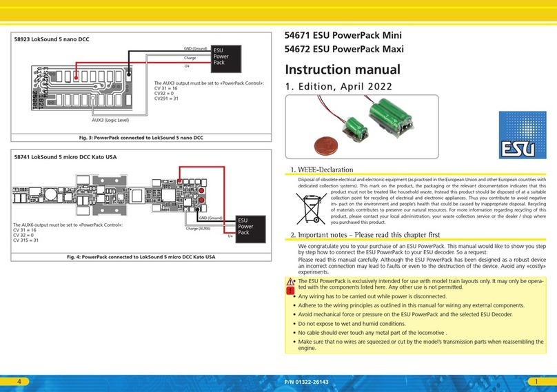
4user manual LokPilot mfx (61600) V1.0 04/2005
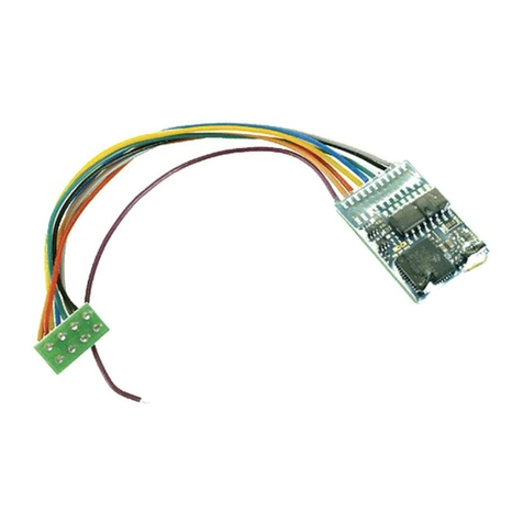
• Locate the decoder at a suitable position within
the locomotive. Most modern models have
sufficient space for a decoder. Use double sided
adhesive tape or a small amount of hot glue.
Locomotives without interface
First separate all wires in the locomotive and make
sure there is no hidden connection from one of the
motor terminals to the chassis or the wheel contacts.
The motor terminals definitely must be insulated.
Fleischmann models often have such a connection,
which can easily be overlooked. Check all connections
using an Ohmmeter and make sure there are no
short circuits between the motor terminals and the
wheel contacts.
How to proceed depends on how the headlights and
auxiliary functions are wired:
a) If directional headlights and functions are isolated
from the locomotive body proceed as per figure 2.
b) Directional headlights and functions may be
connected with their common to the track voltage
(e.g. almost all Märklin® -locomotives and older
Fleischmann or ROCO locomotives are wired like
that) as per figure 3.
• Connect the red wire to the right rail pickup (or
centre pick up in AC models)
• the black wire to the left rail pickup (wheels in AC
models).
• Connect the orange wire with the motor terminal,
which was previously wired to the right wheel pick
up (centre pick up in AC models).
• The grey wire goes to the terminal, which was
originally connected to the left rail (common rails
for AC models).
• Solder the back-up lights to the yellow wire, the
front headlights to the white wire.
• Connect the green wire to the function output,
which you want to switch with function button
F1.
•Connect the purple wire with the function output,
which you want to switch with the function button
F2.
If your locomotive is wired as per b) above, then
wiring is completed.
In the case as per fig. 2 you have to connect the
second pole of all light bulbs or other loads to the
blue wire. The blue wire must not be connected to
the chassis!
Connecting Auxiliary Functions
Any load may be connected to the light and
function outputs as long as it doesn’t exceed the
maximum current. Please note that the overload
protection of the decoder responds very quickly
and will switch off all functions immediately in case
of overload or short circuit.
Therefore use only 16 V bulbs or higher and a
maximum nominal current of 50 mA:
Incandescent lamps have a high starting current
and this may activate the overload protection
of the decoder when the lights are switched on.
Use only digital smoke generators (e.g. Seuthe No.
11) for locomotives whose light and function
outputs are connected as shown in figure 2. All
other smoke generators may draw too much
current. Some commercially available smoke
generators have a higher nominal current than 250
mA!
In locomotives connected as shown in figure 3 an
analogue smoke generator e.g. Seuthe No. 10 is
required.
Make sure that the total current for all function
outputs does not exceed the permitted current
rating and avoid short circuits between outputs.
Although outputs of LokPilot mfx decoders are
protected, high voltage on the terminals or a
short circuit may damage the decoder!
Set-up and initial operation
Before replacing the body and reconnecting the
engine it is recommended to carry out a function
test.
The factory pre-set Motorola address is 03.
The decoder must „report“ automatically
to mfx central units.
• Does the locomotive move in either direction?
• Turn the lights on: are they operating correctly? If
the LokPilot mfx V2.0 decoder is used in a
locomotive with NEM interface: check if the NEM
connector is plugged in correctly.


