Esu LokSound 5 User manual

Installation and Operating Instructions
4. l age, January 2019
P / N 51988
From decoder firmware 5.0.60.
LokSound 5
LokSound 5 micro L
LokSound 5 5 XL
LokSound
LokSound 5

2
1. Declaration ............................................ 6
2. WEEE Declaration ............................................. .......... 6
3. Important Notes - Read This First .................. 6
4. How this manual helps ................. 7
5. Introduction - The LokSound family ......................... 8
5.1. Members of the LokSound family ............................. 8
5.1.1. LokSound 5 ................................................ ...............8th
5.1.2. LokSound micro ............................................... 5 ......8th
5.1.3. LokSound XL ............................................... 5 ........... 9
5.1.4. LokSound 5 L ............................................... .............. 9
5.1.5. The LokSound decoder 5 Overview ..................... 11
5.2. General Properties of all Decoders ...................... 12
5.2.1. Modes ................................................. .......... 12
5.2.2. Sound functions ................................................ 13
5.2.2.1. Functions for steam engines .................................... 13
5.2.2.2. Functions for diesel ..................................... 13
5.2.2.3. Functions for electric locomotives ........................................... 13
5.2.2.4. LokProgrammer ................................................. ... 13
5.2.2.4.1. Compatibility ................................................. ... 14
5.2.3. Analog operation ................................................. ......... 14
5.2.4. Functions ................................................. ............. 14
5.2.5. Programming ................................................. ..... 14
5.2.6. Reliability ................................................. .... 14
5.2.7. Protection ................................................. .................... 14
5.2.8. Future built ................................................ ... 14
6. Installing the Decoder ............................................... ........ 15
6.1. Installation requirements .............................................. 15
6.2. Fastening of the decoder ........................................... 15
6.3. Locomotives with 8-pole NEM652 interface ..................... 15
6.4. Locomotives with 6-pin NEM651 interface ..................... 15
6.4.1. LokSound 5 micro flex PCB ........................... 15
6.5. Locomotives with 21MTC interface according NEM660 ............... 16
6.5.1. Märklin® locomotives with 21MTC ................... 16
contents
6.5.2. Connection of C-Sine motors ( "Soft Drive-Sinus") ..16
6.6. Locomotives with Next18 interface ...................................... 16
6.7. Locomotives with PluX interface .......................................... 17
6.8.1. Wiring diagram LokSound / LokSound micro ......... 25
6.8.2. Connection scheme LokSound 5 L decoder ................ 26
6.8.3. Connection scheme LokSound 5 XL decoder ............... 27
6.8.3.1. Following LGB transmission ................................... 27
6.8.3.2. Following LGB decoder interface .................. 28
6.8.3.3. Following Aristocraft® interface ................. 28
6.8.3.4. Headers decoder ................................................ 29
6.8.3.5 SUSI pins ............................................ .................... 29
6.8.4. Märklin® cable colors ............................................ 30
6.8.5. Motor and track connection ....................................... 30
6.8.5.1. Connecting DC & coreless motors .... 30
6.8.5.2. Connecting Universal Motors with HAMO-conversion .... 30
6.9. Speaker installation ................................................. .... 31
6.9.1. LokSound 5 and 5 LokSound micro ......................... 31
6.9.1.1. Assembly of the resonator body .................... 31
6.9.1.2. use multiple speakers ........................ 32
6.9.2. LokSound XL ............................................... 5 .......... 32
6.9.2.1. Volume control ext. ............................................. 32
6.9.3. LokSound 5 L ............................................... ........... 33
6.9.3.1. Volume control ext. ............................................. 33
6.10. Connecting additional functions ............................... 33
6.10.1. Overload protection function outputs (light flash) ... 33
6.10.1.1. Suitable bulbs ............................................ 34
6.10.1.2. Micro incandescent LokSound 5 XL ................. 34
6.10.2. Using LEDs ........................................... 35
6.10.3. Types of function outputs ............................. 35
6.10.3.1. Function outputs, the decoder 35 .........................
6.10.4. Using enhanced function outputs .......... 35
6.10.5. Using logic outputs ....................... 38
6.10.6. Power outputs ................................................. ..... 38
6.10.6.1 servo outputs LokSound 5 L ......................... 38
6.10.6.2 servo outputs LokSound 5 XL ...................... 39
6.10.7. SUSI / servo / logic outputs ................................... 39

3
6.10.8. Suitable smoke inserts ....................................... 39
6.10.8.1 smoke generator on LokSound 5 L ......................... 40
11.6. Connecting a wheel sensor ....................................... 40
6.11.1. HALL Sensor IC ............................................... ....... 41
6.11.2. Additional sensor inputs .................................. 42
12.6. Connecting Capacitors ........................... 42
6.12.1. LokSound H0, LokSound micro decoder 42 ...............
6.12.2.PowerPack for LokSound micro and LokSound ....... 43
7. Start-............................................... ....... 44
7.1. Work values on delivery ...................................... 44
7.2. Digital modes ............................................... .... 44
7.2.1. DCC operation ............................................... ............. 44
7.2.1.1. DCC speed ( "flashing lights") 44 ............................
7.2.1.2. Automatic DCC speed detection ............. 44
7.2.2. Motorola® mode .............................................. ..... 45
7.2.2.1. 28 speed steps ................................................ ....... 45
7.2.2.2. Extended Motorola® Address Range .................. 45
7.2.3. Selectrix® operating .............................................. ...... 45
7.2.4. M4 operating ............................................... ............... 45
7.3. Analog operation ................................................. ............ 46
7.3.1. Analog DC operation ................................... 46
7.3.2. Analog AC operation ................................ 46
8. Decoder Settings (Programming) ............. 47
8.1. Variable decoder features .......................... 47
8.1.1. M4 configuration area ........................................ 47
8.1.2. M4, the mfx® compatible protocol by ESU ........... 48
8.1.3. Configuration variable (CVs) .................................. 48
8.1.3.1. Standardization in NMRA ......................................... 48
8.1.3.2. Bits and bytes ............................................... ........ 48
8.2. Programming with popular Digital Systems .......... 49
8.2.1. Programming with DCC systems ........................ 49
8.2.2. Programming with ESU ECoS ................................ 49
8.2.3. Programming with Märklin® 6021 ....................... 49
8.2.3.1. Change in the programming mode .................... 49
8.2.3.2. Short Mode ................................................. .......... 50
8.2.3.3. Long mode ................................................. .......... 50
8.2.4. Programming with Märklin® Mobile Station ® 1 ... 50
8.2.5. Programming with Märklin® Mobile Station ® 2 ... 51
8.2.6. Programming with Märklin® Central Station ........ 51
8.2.7. Programming with LokProgrammer ............... 51
8.2.8. Programming with ROCO® Multimaus ................ 52
8.2.9. Programming with ROCO® Lokmaus II ................. 52
9. Address Settings .............................................. 53
9.1. Short addresses in DCC mode .................................. 53
9.2. Long addresses in DCC operation ................................. 53
9.3. Motorola® address .............................................. ...... 54
9.3.1. Subsequent addresses for more features ......................... 54
9.4. Addresses in M4 operation ............................................. .54
9.5. Turning off unneeded data protocols .............. 55
10. Adjust handling ...................................... 55
10.1. Acceleration and braking delay ............. 55
10.1.1. Acceleration / deceleration turn off ..55
10.1.2. Shunting ................................................. ......... 55
10.2. VMin, VMax. and speed characteristics ............ 55
10.3. Switching between the modes ........................ 56
10.3.1. AC digital - analog DC voltage ............. 56
10.3.2. AC digital - analog AC .......... 56
10.3.3. AC analog - digital (wrongdirection) .................. 56
10.3.4. AC digital - digital ........................................ 57
10.3.5. System change when the analog operation ..57
10.4. Braking distances ................................................. .......... 58
10.4.1. DC braking mode ................................................ .... 58
10.4.2. Märklin® braking section .......................................... 58
10.4.3. Selectrix® diodes braking distance .............................. 58
10.4.4. ABC braking mode ............................................... ... 58
10.4.4.1 ABC slow travel section .................................. 58
10.4.4.2. NBC detection threshold ................................... 58
10.4.4.3. ABC shuttle train ................................... 59
10.4.5. ZIMO HLU braking distance ......................................... 59
10.4.6. Braking distance delay .................................... 59
contents

4
10.5. Constant braking distance .............................................. 59
10.5.1. Linear braking ............................................... 60
10.5.2. Constant linear deceleration ................................. 60
10.5.3. Pull trains ................................................. .......... 60
10.5.4. Braking at speed level 0 ......................................... 60
10.6. Brake functions ................................................. ..... 60
10.7. Load simulation ................................................. .......... 61
10.8. Settings for analogue mode ......................... 61
10.8.1. Analog mode ............................................... ... 61
10.8.2. AC analogue mode ............................................... ... 62
10.9. Engine brake ................................................. ........... 62
10.10. Configuring Power Pack ........................................ 62
11. Motor Control ............................................... .... 63
11.1. Adjust load control .............................................. 63
11.1.1. Parameter for frequently used Motors ............ 63
11.1.2. Adjustments for other Motors / "Fine Tuning" ...... 63
11.1.2.1. Parameter "K" .............................................. ...... 63
11.1.2.2. Parameter "I" .............................................. ....... 63
11.1.2.3. Control reference .............................................. 64
11.1.2.4. Parameter "K slow" ............................................ 65
11.1.2.5. "K slow Cutoff" ............................................. .... 65
11.1.2.6 control influence when traveling slowly ..................... 65
11.1.3. Measuring method of the EMF control ......................... 65
11.1.3.1. Measurement period ................................................. ....... 65
11.1.3.2. Blanking interval ................................................. ...... 66
11.1.4. Automatic motor calibration .................... 66
11.2. Load control switch off ............................................ 66
11.3. Adjust load control frequency ............................... 66
11.4. Settings for C-Sinus Motor ............................... 66
12 function outputs .............................................. 68
12.1. Function outputs ............................... 68
12.2. Function key assignment (mapping function) ......... 68
12.2.1. CV indexed access .............................................. 68
12.2.2. Function key assignment .................................... 68
12.2.2.1. Condition block 72 ................................................
contents
12.2.2.2. Physical outputs ........................ 74
12.2.2.3. Logic functions ................................................. .74
12.2.2.4. Sound functions ........................................... 76
12.3. Standard mapping LokSound 5 .................................. 76
12.3.1. Example ................................................. ................. 77
12.4. Function key assignment with the LokProgrammer .77
12.5. Configuring the function outputs ....................... 79
12.5.1. Possible light effects and options .............. 80
12.5.2 procedure for configuring .......................... 81
12.5.2.1. Special functions 1 and 2 ................................. 81
12.5.3. Grade Crossing holding time ........................................ 84
12.5.4. Flashing frequency ................................................. ........ 84
12.5.5. Automatic shutdown .................................... 84
12.5.6. Switch-off delay and ..................... 84
12.5.7. Digital clutches ................................................. 85
12.5.7.1. Mode "coupler" ....................................... 85
12.5.8. Power settings ................................................. 85
12.6. Input configuration wheel sensor LokSound 5 H0 .... 85
12.7. Settings for analogue mode ................................ 86
12.8. LGB® chain control ............................................. 86
12.9. Swiss headlight mode ............................................. 86
13 sound adjustments ........................................ 87
13.1. Adjust the volume ................................................ ..87
13.1.1. Total volume level set ........................... 87
13.1.2. Single sound table ............................................. 87
13.1.2.1. Table for steam locomotive sounds ........................... 87
13.1.2.2. Table for diesel noise ................................. 88
13.1.2.3. Table for electric locomotive sounds ................................ 88
13.1.2.4. Table for special noise ............................... 89
13.2. Starting delay ................................................. .89
13.3. Electronic steam synchronization ................. 89
13.3.1. Minimal steam distance .............................. 90
13.4. Set Brake sound threshold ............................. 90
13.5. Sound fader ................................................. .............. 90
13.6. Volume control ................................................. ..90

5
contents contents
14 random functions ............................................... .. 91
15. Decoder Reset ............................................. ......... 92
15.1. With DCC systems or 6020/6021 ......................... 92
15.2. With Märklin® systems (using mfx®) ..................... 92
15.3. With LokProgrammer ........................................... 92
16. Special functions ............................................... . 92
16.1. Wrong-................................................. ............ 92
17. RailCom® .............................................. ................ 93
17.1. RailComPlus® ................................................ ........... 93
17.1.1. Requirements for RailComPlus® ....................... 93
18 Firmware Update ............................................... .... 93
19 Accessories ............................................... ................. 94
19.1. Change over ................................................ 94
19.2. HAMO Magnets ............................................... ........ 94
19.3. Cable sets with 8-pin. or 6-pol. Socket .................. 94
19.4. Adapter boards ................................................. ...... 94
20. Support and assistance ............................................. ... 95
21 CV Table sound decoders ............................ 96
22. Change History ............................................. 106
23. Annex ............................................... ................ 107
23.1. Programming long addresses .............................. 107
23.1.1. Write Address ................................................ 107
23.1.2. Address read ................................................ ..107
24. Guarantee certificate ............................................... . 108
6
1. Declaration of Conformity
The manufacturer, ESU GmbH & Co. KG, EDI sonallee 29, D-89231 Neu-Ulm,
hereby declares under sole responsibility responsi- that the product
Product name: LokSound 5, 5 LokSound micro, LokSound 5 L, XL
LokSound 5
Type: 584xx, 588xx, 583xx, 585xx
cal all relevant provisions of Directive Electromagnetic Compatibility (2004/108 /
EC). The following harmonized standards were applied:
EN 55014-1: 2006 + A1: 2009: Electromagnetic Compatibility
- Requirements for household appliances, electric tools and similar apparatus -
Part 1: Emission
EN 55014-2: 1997 + A1: 2001 + A2: 2008: Electromagnetic compatibility -
Requirements for household appliances tools, Elektrowerk- and similar
apparatus - Part 2: Immunity.
2. WEEE Declaration
Disposal of old electrical and electronic equipment (applicable in the European
Union and other European countries with separate ratem collection systems).
This symbol on the product packaging or in the document
mentation means that this product may not be treated as
household waste. Instead, it should be brought to the
appropriate disposal point for recycling of electrical and
electronic boards. If the product is disposed of correctly, you
will help negative environmental influences
prevent sen and health that could be caused by improper disposal. Recycling of
materials contributes to preserve our natural resources. Contact you for more
information regarding recycling of this product, your local city office, your waste
collection service or the shop where you bought this product.
Important instructions
Copyright 1998 - 2019 by ESU GmbH & Co KG. Errors, changes that serve technical
advancement, availability and all other rights reserved. Electrical and mechanical measurements
and pictures without guarantee. Any liability for damages and consequential damages caused by
improper use, abnormal operating conditions, unauthorized modifications to u. ä. is excluded.
Not suitable for children un- ter 14 years. Improper use may cause injury. Märklin® and mfx®
are registered trademarks of Gebr. Märklin® und Cie. GmbH, Göppingen. RailCom® is a
registered trademark of Lenz Elektronik GmbH, Giessen. All other trademarks are the property of
their respective owners. ESU GmbH & Co. KG operates a policy of continuous development.
Therefore ESU reserves the right to make on each of the described in the documentation
process-products changes and improvements without notice. Duplications and reproductions of
this documentation in any form without the prior written consent of ESU.
3. Important Notes - Read This First
Congratulations on your purchase of an ESU LokSound decoder. This manual
will guide you step by step through the features of the decoder closer. Therefore,
one request: Please read this manual before you start using care- fully. Although
all sound decoders are robustly constructed there an incorrect connection may
lead to destruction of the device. Renounce any "costly" experiments.
• The LokSound is solely intended for use with electrical model-railway
installations. He may only be operated with the described in this manual
components. Any use other than that described in these instructions is not
permitted.
• Any wiring has to be carried out while power is disconnected operation. Make
sure that during the renovation never safe - even accidentally - can enter a
voltage to the locomotive.
• Avoid mechanical force or pressure on the decoder.
• remove the shrink sleeve on the decoder.

7
4. How to use this manual
This manual is divided into several chapters that show you step by step what is
carried out as. Chapter 5 provides an overview of the characteristics of each
sound decoders.
In Chapter 6 of the installation is described in detail. Please comparable to
provide an overview of the installed in the locomotive engine before then -
depending on the installed in your locomotive interface - one of the sections 6.2.
to 6.12. should work through.
Sound decoders can be used with most control systems. Chapter 7 provides an
overview which digital and analogue systems LokSound and which special
issues to consider. The default function key assignment is described in Section
7.1. to find.
If you wish, you can adjust the default settings of your LokSound decoder
individually. Chapters 8 to 17 ex- plain to you which settings are possible and
how you can change settings.
We encourage you to at least the chapters 8 and 9 resseinstellungen over ad
and to read the chapter 11 on the motor control to adjust your LokSound
perfectly to the engine of your model.
Details of the technical data in Section 5.1.5. and a list of all supported CVs
further help if required. Unless otherwise indicated, the information refers to all
members of the LokSound family. If a Deco of a particular function does not
support, this is explicitly mentioned.
How to use this manual
• No cable must never touch the metal parts of the locomotive, even
accidentally or temporarily! Insulate the bare end of unnecessary cables.
• Solder never directly on the decoder. Extend the cable if necessary, or use an
extension cord.
• Never wrap the decoder in a tape. This heat dissipation prevents overheating
would be possible.
• Upon connecting the external components to the principles presented in this
manual is. The use rer On the other circuits can lead to damage of the
decoder.
• When assembling the locomotive that no Ka bel be squeezed or short circuits
occur.
•All power sources must be protected so that it can not in a cable fire in the
event of a short circuit. Comparable contact only commercially available and
manufactured according to VDE / EN model train transformers.
• Operate the sound decoders unattended. The sound decoders is not a
(children's) toy.
• Do not expose to moisture and humidity.
• Treat the loudspeaker during installation extremely care: Do not print out and
touch the loudspeaker not chermembrane! Solder quickly to the designated
places!

8th
Introduction - The LokSound family
5. Introduction - The LokSound family
5.1. Members of the LokSound family
The sound decoders fifth generation has been completely redeveloped. It
combines intelligently a sound module with a multi-protocol digital decoder.
Thus, a einzi- ger component to both the vehicle and the sound operation of the
locomotive is sufficient to map.
By using a new, high-performance 32-bit processor all the properties of the
previously known LokSound Deco could the be significantly improved once
again: LokSound 5 Deco of playing up to 10 sound channels simultaneously,
each channel thanks to 16-bit resolution and 31250 kHz Sample rate HiFi
achieved quality. With a LokSound decoder 5, the sound quality and dynamic
range of your locomotives are almost perfectly measure up to the original. 128
Mbit noise memory provide sufficient capacity reserves.
LokSound decoder 5 feature a further improvement in engine load control with
up to 50 kHz clock frequency and noise-optimized motor control, so that coreless
or trace-1 engines in the future at excellent Langsamfahreigenschaf- th silently
approached.
have for the control of lighting and additional functions locomotive sound
decoder 5 numerous outputs and can control when needed RC servos and SUSI
modules.
Each LokSound decoder 5 is also a true multiprocessor protocol decoder with all
four known data formats: In addition to DCC with RailComPlus all understand
the M4 format and automatically log on to modern Märklin® stations. Lower
support for Motorola and Selectrix make use with older centers possible. In
addition, each (N also track!) LokSound 5 can be driven decoder
selstromanlagen on analogue DC and exchange. The desired mode is
automatically detected.
Depending on the center up to 32 functions are possible, which can be assigned
with the unique flexible ESU function mapping arbitrary with special functions.
Three new, individually adjustable
bare brake controller and a two-stage heavy duty simulation bring functions as
additional enthusiasm as the new Zufallsfunk-, with the help of which light effects
can be controlled by chance.
Future standards are no problem: With flash technology, the decoder can always
be brought up to date. For this, the proven LokProgrammer is set once.
To accommodate different sizes and power requirements of the vehicle to meet
witness, LokSound decoders are offered 5 each with different characteristics that
we want to introduce to you.
5.1.1. LokSound 5
The LokSound 5 decoder is designed for locomotives for H0 and trace 0th With
its normalized standard size of 30mmx15.5mm it should find its place in almost
every locomotive. The LokSound decoder 5 is offered with all common
interfaces. Up to 14 function outputs are - depending on the interface - available.
An external power pack can be connected optionally.
Thanks to its extensive light and sound functions as well as its engine power
output of 1.5A he is the perfect "all-round decoder" for your locomotives. The
LokSound decoder 5 is supplied from the factory set with a 11x15mm "sugar
cube" speakers along with a customizable Schallkapsel-.
5.1.2. LokSound micro 5
The LokSound micro 5 is a little powerhouse: Despite its ex- tremely small
dimensions of only 21mm x 10mm it goes next with DCC RailComPlus® also
M4®, Motorola® and Selec- TRIX® and can also (on analogue DC and AC! )
systems are operated.
With up to 9 function outputs you can finally equip from smaller vehicles with
prototypical lighting functions. an ex-

9
Introduction - The LokSound family
ternes Power pack can optionally be connected. The Mo torausgangsleistung of
0.75A is suitable where space is limited for most all applications.
The LokSound micro 5 is always supplied with a standardized interface Next18-.
Matching each supplied adapter cables provide the connection to the respective
engines.
The LokSound micro decoder 5 is supplied from the factory with a 11x15mm "sugar
cube" speakers along with a customizable Schallkapselset.
5.1.3. LokSound XL 5
The LokSound 5 XL has been designed for the wide track and trace G 1 and
optimized. 41mm its dimensions of 55 x has established itself as the standard for
almost all Track 1 vehicles. The LokSound XL 5 leaves with his motor current
from 5A up to 19 outputs for special functions and connection options for four
additional RC servos little to be desired: The Sophisticated model railroaders
can adapt its vehicles to the smallest detail to the model. While the double
amplifier provides outdoor seating for punchy sounds, including problems due to
dirty rails thanks to the integrated power pack of the past. LokSound 5 XL will be
available in two versions: The version with screw terminals suitable for individual
cabling, while the version with pin headers to almost all Spur1- Model len
Märklin®, KISS®,
5.1.4. LokSound 5 L
The LokSound 5 L finds its place between the 5 and the LokSound LokSound 5
XL. With its dimensions of only 51mmx25.5mm it is recommended not only for
vehicles of nominal size 0, but also for all other vehicles where a LokSound 5 XL
does not fit or necessary. The LokSound 5 L offers a motor starting current of 3A
up to 14 function outputs, as well as the connection for two RC servos. His dual
power amplifier can drive two speakers. Thanks to the now integrated power
packs are dirty rail NEN of the past. The decoder is always supplied with male
connectors and a suitable adapter board.

10
5.1.5. The LokSound decoder 5 at a glance
LokSound 5 LokSound micro 5 LokSound 5 L LokSound XL 5
DCC operation OK OK OK OK
Motorola® operation OK OK OK OK
M4 mode (mfx® compatible) OK OK OK OK
Selectrix® operation OK OK OK OK
Analogue DC operation OK OK OK OK
Analogue AC Operation OK OK OK OK
DCC programming OK OK OK OK
Programming with 6021, Mobile / Central Station ® OK OK OK OK
M4 programming and automatic login OK OK OK OK
RailCom® with RailComPlus® OK OK OK OK
ABC, Selectrix®, Märklin®, HLU braking sections OK OK OK OK
ABC shuttle OK OK OK OK
LokSound 5 Sound Engine 10 channels, 16-bit stereo, 128 MBit memory 10 channels, 16-bit stereo, 128 MBit memory 10 channels, 16-bit stereo, 128 MBit memory 10 channels, 16-bit stereo, 128 MBit memory
Audio outputs 1 amplifier, Class D, 1.5W sinus (3W music). 4 Ohm - 32 Ohm 1 amplifier, Class D, 1.5W sinus (3W music). 4-32 ohms 2 amplifiers Class D, depending 1.5W sinus (3W music). 2 amplifiers, Class D, depending 3.0W sinus (6W music)
Motor current period 1.5A 0.75A 3.0A 5.0A
Power Pack buffer integrated - - Yes, 2x 1F / 2.7V Yes, 2x 5F / 2.7V
Connection for Power Pack OK OK OK OK
Item number 58410 58416 58419 58449 58412 58810 58816 58818 58814 58315 58513 58515
connection 8pin 6pin 21MTC 21MTC MKL PluX22 8pin 6pin Next18 PluX16 pin header screw Headers
harness harness Directly Directly Directly cable adapter cable adapter Directly adapter plug adapter board Adapter board (option)
function outputs 10x Power 1x logic
level or power pack 1x
logic level or wheel
sensor
10x Power 1x logic
level or power pack 1x
logic level or wheel
sensor
10x Power 1x logic level or
Power Pack 1x logic level
instead of wheel sensor 2x
logic level instead of SUSI
10x Power 1x logic level or
Power Pack 1x logic level
instead of wheel sensor 2x
logic level instead of SUSI
10x Power 1x logic level or
Power Pack 1x logic level
instead of wheel sensor 2x
logic level instead of SUSI
6x Power 1x logic
level or Power Pack
6x Power 1x logic
level or Power Pack
6x Power 1x logic
level or Power Pack
2x logic level instead
of SUSI
6x Power 1x logic
level or Power Pack
2x logic level instead
of SUSI
11x Power 1x logic level instead of wheel sensor
2x logic level instead of SUSI 2x logic level
instead Servo3 / Servo4 1x Smoke Unit Heating
1x Smoke Unit Motor Control
12x Power 1x 2x logic level logic
level instead of SUSI 4x logic
level instead Servo1-4
12x Power 1x 2x logic level logic
level instead of SUSI 4x logic
level instead Servo1-4
inputs 1x wheel sensor 1x wheel sensor 1x wheel sensor 1x wheel sensor 1x wheel sensor 1x wheel sensor 2x sensor input 1x motor
off ( "display mode") 1x Smoke Unit
temperature sensor
1x wheel sensor 2x
sensor input
1x wheel sensor 2x
sensor input
Power outputs 2x instead of SUSI 2x instead of SUSI 2x instead of SUSI 2x instead of SUSI 2x instead of SUSI 2x fixed, 2x instead of SUSI 4x fix, 2x instead of SUSI 4x fix, 2x instead of SUSI
Dimensions in millimeters 30,5x15,5x5,5 30,5x15,5x5,5 30,5x15,5x5,5 30,5x15,5x5,5 30,5x15,5x5,5 25,5x10,6x4,5 25,5x10,6x4,5 21,0x10,6x4,0 21,0x10,6x4,0 51,8x25,4x14,0 51,0x40,0x14,0
The LokSound decoder 5 at a glance

11
5.1.5. The LokSound decoder 5 at a glance
LokSound 5 LokSound micro 5 LokSound 5 L LokSound XL 5
DCC operation OK OK OK OK
Motorola® operation OK OK OK OK
M4 mode (mfx® compatible) OK OK OK OK
Selectrix® operation OK OK OK OK
Analogue DC operation OK OK OK OK
Analogue AC Operation OK OK OK OK
DCC programming OK OK OK OK
Programming with 6021, Mobile / Central Station ® OK OK OK OK
M4 programming and automatic login OK OK OK OK
RailCom® with RailComPlus® OK OK OK OK
ABC, Selectrix®, Märklin®, HLU braking sections OK OK OK OK
ABC shuttle OK OK OK OK
LokSound 5 Sound Engine 10 channels, 16-bit stereo, 128 MBit memory 10 channels, 16-bit stereo, 128 MBit memory 10 channels, 16-bit stereo, 128 MBit memory 10 channels, 16-bit stereo, 128 MBit memory
Audio outputs 1 amplifier, Class D, 1.5W sinus (3W music). 4 Ohm - 32 Ohm 1 amplifier, Class D, 1.5W sinus (3W music). 4-32 ohms 2 amplifiers Class D, depending 1.5W sinus (3W music). 2 amplifiers, Class D, depending 3.0W sinus (6W music)
Motor current period 1.5A 0.75A 3.0A 5.0A
Power Pack buffer integrated - - Yes, 2x 1F / 2.7V Yes, 2x 5F / 2.7V
Connection for Power Pack OK OK OK OK
Item number 58410 58416 58419 58449 58412 58810 58816 58818 58814 58315 58513 58515
connection 8pin 6pin 21MTC 21MTC MKL PluX22 8pin 6pin Next18 PluX16 pin header screw Headers
harness harness Directly Directly Directly cable adapter cable adapter Directly adapter plug adapter board Adapter board (option)
function outputs 10x Power 1x logic level or power pack 1x logic level or wheel sensor10x Power 1x logic level or power pack 1x logic level or wheel sensor10x Power 1x logic level or Power Pack 1x logic level instead of wheel sensor 2x logic level instead
SUSI
10x Power 1x logic level or Power Pack 1x logic level instead
2x wheel sensor logic level instead
SUSI
10x 1x Power Level logic or
Power Pack 1x logic level instead
2x wheel sensor logic level instead
SUSI
6x Power 1x logic
level or Power Pack
6x Power 1x logic
level or Power Pack
6x Power 1x logic
level or Power Pack
2x logic level instead
of SUSI
6x Power 1x logic
level or Power Pack
2x logic level instead
of SUSI
11x Power 1x logic level instead of wheel sensor
2x logic level instead of SUSI 2x logic level
instead Servo3 / Servo4 1x Smoke Unit Heating
1x Smoke Unit Motor Control
12x Power 1x 2x logic level logic
level instead of SUSI 4x logic
level instead Servo1-4
12x Power 1x 2x logic level logic
level instead of SUSI 4x logic
level instead Servo1-4
inputs 1x wheel sensor 1x wheel sensor 1x wheel sensor 1x wheel sensor 1x wheel sensor 1x wheel sensor 2x sensor input 1x motor
off ( "display mode") 1x Smoke Unit
temperature sensor
1x wheel sensor 2x
sensor input
1x wheel sensor 2x
sensor input
Power outputs 2x instead of SUSI 2x instead of SUSI 2x instead of SUSI 2x instead of SUSI 2x instead of SUSI 2x fixed, 2x instead of SUSI 4x fix, 2x instead of SUSI 4x fix, 2x instead of SUSI
Dimensions in millimeters 30,5x15,5x5,5 30,5x15,5x5,5 30,5x15,5x5,5 30,5x15,5x5,5 30,5x15,5x5,5 25,5x10,6x4,5 25,5x10,6x4,5 21,0x10,6x4,0 21,0x10,6x4,0 51,8x25,4x14,0 51,0x40,0x14,0

12
l 5.2.2. motor controll 5.2.2. motor control
The main function of a digital decoder is control the motor. All LokSound 5
decoders are universal and can be used with all the models commonly available
DC motors, regardless if ROCO®, Fleischmann®, Brawa®, Mehano®, Bemo®,
LGB, Märklin® or others. Even coreless motors (eg Faulhaber® or Maxon®) can
be connected.
Current motors you can continue to use, provided you replace the stator coils by
a permanent magnet. For more details see chapter 6.8.5.2.
The load regulation of the 6th generation works with an adjustable
high-frequency control between 10 and 50 kHz and assures extremely silent,
smooth motor operation, particularly with coreless motors. Your locos will crawl
super slowly thanks to 12-bit A / D technology. The load control can be easily
adapted to different engine and transmission combinations (see. Chapter 11).
The minimum and maximum speed of 5 LokSound can be adjusted with two
points that can be customized on request with a speed table with 28 entries. By
ESU unique mass simulation no abrupt transitions are visible even when only 14
speed steps. can now also the PWM measurement period and the length of the
blanking interval to be adjusted for "difficult cases".
General Properties of all Decoders
5.2. General Properties of all Decoders
5.2.1. modes
All LokSound decoder 5 are true multi-protocol decoders with automatic
detection of the operating mode "on-the-fly". The decoder analyzes the track
signal and filters each for Him certain out package. Changing from digital to
analogue and back without any problems. This is important in case your shadow
station is still controlled conventionally. Further acknowledge and follow all
LokSound decoders support the relevant brake modes such as ROCO®, Lenz®
or Märklin® and lead-ben are correct.
In particular, the ABC brake sections are suitable for simple chen signal stop.
Sound decoders are aligned with a high degree of compatibility with the
particular system in order to even infrequent applications.
LokSound 5 dominate the DCC protocol with 14, 28 or 128 speed steps and
recognize automatically the correct setting even. Operation with the long 4-digit
addresses is possible as well.
LokSound loading prevail up to 255 addresses and 28 speed steps for
Motorola® operation certain 5 decoder. With a corresponding center such as the
ESU ECoS you can greatly expand as the Motorola® system boundaries.
All LokSound decoders handle 5 in addition rail ComPlus®. In connection with
so-equipped Digitalzent- eral these decoders report automatically to the head
office and transfer all relevant data. Finally, you'll never have to search for the
address of the locomotive and tedious keys function connect!
All LokSound decoders understand the 5 mfx® compatible M4 data format, and
thus sign up Märklin® mfx® central independently on.

13
The unlimited (!) Number of possible Chuffs use our sound engineer from
skillfully.
Steam whistles attached directly to the function button, which allows you to control
the length of the whistle well. Moreover, it is (where superiors see) the finale of
catcalls different depending on the operating condition.
5.2.2.2. Functions for diesel locomotives
The diesel traction was and still is an important art drive. Of course, the
LokSound 5 carries this into account. Usually three sound channels ensure a re-
alistische representation of modern diesel-electric locomotives (diesel engine,
driving engine and turbocharger can simulate separately lines). For example, an
unlimited number of speed steps - are represented - also dependent on the load.
But diesel-hydraulic locomotives with Wendegetrie- ben, Voith® converters and
the typical continuous whine of the engines, the LokSound 5 convincingly real.
Even railcars with manual transmission can be simulated and displayed.
5.2.2.3. Functions for electric locomotives
Electric locomotives are an indispensable part of the train everyday. And their
noise can be distinguished: The LokSound decoder 5 for example, controls the
fan for the traction motors, the traction motors themselves, brake and oil cooler
on separately. Pantographengeräusche, main switch, TR switch during
acceleration are here as "in", such as the howling of Tatzlagergetrieben when
starting or rod rattle of old electric locomotives.
5.2.2.4. LokProgrammer
All sounds of the sound decoders can be deleted LokProgrammer and copied
using the ESU. To this end, ESU offers hundreds of already prefabricated sound
projects for cost-tenlosen download. Specialists can create their own sounds
completely or modify existing ESU projects.
General Properties of all Decoders
5.2.2. sound functions
Twenty years after the launch of the first LokSound decoder 5 in 1999 occupied
the LokSound again our expertise in the construction of sound decoders. Heart
theLokSound 5 decoder is a powerful 32-bit processor, which makes it possible,
10 sound channels play to ERS in real time.
The sound quality of the LokSound decoder 5 for the first time reached Hi-Fi
audio quality with 16-bit audio and a sample rate of 31250 kHz. The reproduced
sounds are virtually indistinguishable from the original; it reproduced all audible
frequencies. The 128 Mbit large flash memory chip, the stored sounds - take
probemlos - all original sounds of the great role model.
ESU records the original sounds using digital technology to modernster directly
to the locomotives. ESU own sound technicians prepare them in the recording
studio before transferring to the decoder to. All LokSound decoders have 5
ensures the good sound on your system a digital class "D" amplifiers with up to 3
watts of power output (or 13 watts for the LokSound XL 5), the processing
speakers in conjunction with matching high-. All sounds can be changed
individually in volume to meet your own taste. Up to 32 th by function keys
releasable additional sounds offer a startling real-riding experience in
conjunction with automatic run of random sounds and radsynchronem brake
squeal.
5.2.2.1. Functions for steam engines
LokSound decoder 5 can reproduce two-, three- and Vierzylinderdampf- loks. It
does not matter whether it is conventional or composite Liche locomotives. Also
Mallet locomotives with independent engines are conceivable. Three sound
channels that are mixed individually depending on operating status, ensure a
faithful steam locomotive sound on your arrival location. Of course, open cylinder
valves at departure, rattling boom during coasting and violently changing the
load bursts of steam for the LokSound 5 no problem.

14
5.2.2.4.1. compatibility
All sound projects created for LokSound V4.0 can be automatically converted by
the LokProgrammer and loaded onto LokSound decoder 5. The LokSound 5 is
100% backward compatible.
5.2.3. analog operation
In analogue mode, you can not only start-and maximum speed of the locomotive
set and determine which should be active functions: Even load control is active!
5.2.4. features
Individually programmable acceleration and deceleration times, switch the
shunting and adjustable acceleration and braking times are natural for LokSound
decoder 5. All function outputs can be set separately in brightness and assigned
functions.
Available are dimmer, firebox flicker, Gyra and Mars light, and double strobe,
flashing and exchange selblinken also time-limited functions (eg for coupler) and
a clutch function for Krois- and ROCO® including automatic check-in and pull
the trigger "clutch Waltz" , Each LokSound decoder 5 may wish to at least 2, 5
LokSound XL decoders are driven directly to 6 RC servos. The again for the
LokSound 5 improved, unique ESU function mapping allows you to assign each
function freely to keys F0 to F32, even multiple times. Chapter 12 provides more
information.
5.2.5. programming
LokSound decoders support all DCC programming modes domestic klusive
POM (main track programming). Programming can be done by all NMRA DCC
compatible control panels. For Märklin® stations 6020, 6021, Mobile station and
central station, all settings are taken electronically forward. For these units
dominate LokSound decoder 5 a proven, easily acquired programming
procedure. A particularly convenient feature is the setting of parameters for
owners
our ECoS command station: All options are displayed in plain text on the large
screen and can be changed in the simplest way - even during operation! 5
LokSound decoder mfx® on Märklin® stations automatically read and can be
programmed graphically there (with the exception of the function mappings).
5.2.6. operational safety
LokSound decoder 5 possess highly dimensioned Pufferkonden- capacitors and
a precise energy management in order to ensure safe operation without
Geräuschausetzer nenabschnitten also rather critical rail. For locomotives with
problematic power consumption of the connection of an external power pack
energy store can be considered; on the Large Scale Decoder LokSound
LokSound 5 L and XL 5 is soldered at the factory this power pack.
5.2.7. protection
All function outputs and the motor connection are protected against overloading
and short circuits. We want you to possible lichst continued enjoyment of the
LokSound have decoders.
5.2.8. built-in future
All LokSound decoders are 5 thanks to flash memory firmwareup- date capable.
New (software) functions can be retrospectively added at any time.
General Properties of all Decoders

15
Installing the decoder
6. Installing the Decoder
6.1. installation requirements
The engine must be before the conversion in perfect technical condition: Only a
locomotive with faultless mechanical properties and smooth analogue mode
should be digitized. Wearing parts such as motor brushes, wheel contacts, light
bulbs, etc. must be checked and cleaned or replaced.
Be sure to check the instructions in section 3 in order to prevent damage to
the decoder during installation!
6.2. Fixing the decoder
The components of the decoder must not touch the metal parts of the locomotive
as this may cause short circuits and destruction of the decoder in any case.
Therefore, all sound decoders are provided (with the exception of the decoder with
21MTC interface or PluX interface) in a protective heat-shrinkable tube.
Never wrap the decoder in a tape. The air circulation around the decoder is
otherwise prevented, which may cause heat to build up and destruction of the
decoder. Glue the metal parts of the locomotive rather with insulating tape.
Bring the decoder please contact an appropriate, mostly space provided place
in the model below. Attach if provided the de coder with double sided tape or
(very little) hot glue.
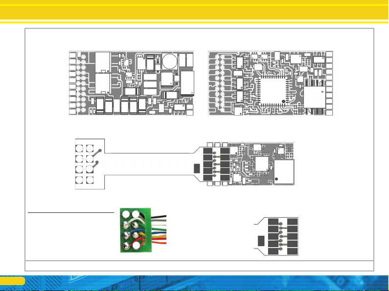
6.3. Locomotives with 8-pin interface NEM652
Some LokSound decoder 5 with an 8-pin digital interface according NEM652
supplied (see. Fig. 1). Therefore, the installation in locomotives with this
interface is particularly easy:
• Remove the vehicle housing. Always follow the instructions of the locomotive!
• Remove the interface plug located in the locomotive. Keep the plug carefully.
• Plug the interface plug now such a way that pin 1 of the connector (this is the
side of the decoder plug with the red / orange wire) on the usually marked with *,
+, • or one side of the interface. Make sure that none of the legs is straight when
inserting bends. Do not rely on the fact that the cables of the connector have to
lead to a specific page: Decisive alone is the pin 1 marking the interface.
6.4. Locomotives with 6-pin interface NEM651
Some LokSound decoder 5 with a 6-pin digital interface NEM651 supplied (see.
Fig. 2). Installation in locomotives with this interface is particularly easy:
• Remove the vehicle housing.
• Remove the interface plug located in the locomotive.
• Plug the interface plug now such a way that pin 1 of the connector (this is the
side of the decoder plug with the orange-gen cable) is at the usually marked with
*, +, • or one side of the interface. Make sure that flexes stuck when entering any
of the legs or tilted.
6.4.1. LokSound 5 micro flex PCB
The wiring harness of the LokSound micro decoder 5 th as Flex Leitplat- run and
einge- in the Next18 interface factory plugged delivered. By this technique, the
total thickness of LokSound 5 could be micro substantially reduced. In addition,
manual soldering at the decoder omitted.

16
Installing the decoder
The flexible printed circuit board is tightly folded to length and thus shortened.
Fold the printed circuit board by hand, making sure that the bends are too often
bent to avoid breaks of the traces. Would you wire your decoder completely free,
you can cut the flexible printed circuit board with sharp scissors directly to the
decoder part and subsequently bring desired on the adapter's cable connections.
The pin assignment is shown in FIG. 2.
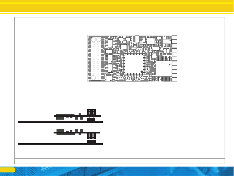
6.5. Locomotives with 21MTC after NEM660
Some LokSound decoders are available in a variant for the 21MTC (see. Fig. 3).
Installation in locomotives with DIE serial interface is particularly simple,
because the decoder is also fastened mechanically by the special design of the
connector.
Please check if the impedance of the built-in loud- speaker really has 4 or 8
ohms! Some locomotives have speakers built with 100 ohms, as they were
originally designed for a LokSound V3.5 decoder.
• Remove the vehicle housing. Always follow the instructions of the locomotive!
• Remove the interface plug located in the locomotive. Keep the plug carefully.
• Search the PCB of the locomotive for the missing pin of the plug connector. The
lack of pen used for encoding. Note its position.
• The decoder can be inserted in two ways: either the pins are inserted through
the decoder, the socket of the decoder remains after plugging therefore visible
(installation position above). Or, the decoder is so inserted that the pins end up
directly in the socket. After inserting the connector is no longer visible here
(mounting position below). This method is common to find in Brawa®
locomotives.
• What is the correct position depends on the locomotive. The decisive factor is
the position of the marker-pin on the crucial indicator.
• Plug the decoder so that the coding of the locomotive interface corresponds
with the decoder.
• Practice when inserting too much force! The decoder must be easily plugged in
without much effort.
• Check whether the decoder sits correctly.
6.5.1. Märklin® locomotives with 21MTC
Unfortunately, many newer Märklin® locomotives, but also some British
locomotives with 21-pin interface does not adhere to the normgemä- SSE
interpretation of 21MTC. These locomotives expect AUX 3 and AUX 4 amplified
signals at the outputs. In these Fäl- len you have to resort to a LokSound
decoder with 5 21MTC "MKL" execution. At these decoders the outputs AUX3
and AUX 4 are designed strengthened. The installation itself is as described in
Section 6.5. shown.
6.5.2. Connection of C-Sine motors ( "Soft Drive-Sinus")
The sound decoders can (also "Soft Drive-Sinus") does not control the built in
newer Märklin® models with C-Sine motors directly. For this purpose, a special,
located in the locomotive factory control board is needed, which in turn can be
driven by a sound decoders. Märklin® uses the 21MTC and use either the
normal engine signals theLokSound decoder or a SUSI interface for information
exchange. The LokSound 5 with 21MTC suitable for that can be triggered ng the
C-Sine control electronics provided some parameters are set correctly. Chapter
11.4. explains the necessary attitudes.
6.6. Locomotives with Next18 interface
Some LokSound decoders are delivered with a 18-pin Next18 interface.
Installation is carried out in accordance with in section 6.6. described. Fig. 4
shows the pin assignment.

17
6.7. Locomotives with PluX interface
Some sound decoders are respectively PluX16-a. PluX22- plug delivered (See.
Fig. 5 and Fig. 6). The plug connector on the decoder has a missing pin
(index-pin). In the locomotive, the position should be marked out. Be sure to
observe the correct position within the PluX interface!
LokSound decoder 5 adhere to the held in VHDM RCN-122 standard interface,
so the index pin is not connected. Unfortunately, some locomotives expect at
this point an output because Zimo not connected this pin in accordance with
standards and. These locomotives do not match the PluX22 standard.
Some ROCO locomotives expect instead of SUSI pins 3 and pin 4 a (logic
level) output function. Also this extension is not in accordance with standards.
At all LokSound decoders 5 SUSI pins can be switched to logic level function
outputs.
6.8. Locomotives without interface
All LokSound decoders are delivered with an interface overall factory. There is
no execution "with cables." Please remove if necessary the interface connector
right at the end of the strands. Please extend any wires at the decoder. If
necessary, use an extension cord.
The Fig. 9 and Fig. 10 show the general connection diagram of a LokSound 5 or
LokSound 5 micro decoder.
Installing the decoder
18
Installing the decoder
Figure 1: 5 & LokSound LokSound 5 micro 8-NEM652 interface Polinger
58410 LokSound 5
front
Speaker # 1 Speaker
# 2 -Motoranschluss right
-Gleisanschluss right -
Rear light -U +
(positive pole) -
AUX1 (Power) -
Light Front
-Gleisanschluss left
-Motoranschluss left -
back
-- AUX8 (Power)
-- AUX7 (Power)
-- AUX6 (Power)
-- AUX5 (Power)
-- AUX4 (Power)
-- AUX 3 (Power)
-- VCC
-- AUX10 / wheel sensor
-- GND
-- AUX9 / PwrPackCtrl
-- U + (+ pole)
AUX9, AUX10 are logic level outputs and inputs
58810 LokSound micro 5
AUX7 is logic level output (Default: PwrPackCtrl)
pen assignment colour
1 Motor connection right orange
2 Rear light yellow
3 AUX1 green
4 Left track connection black
5 Left motor terminal Gray
6 Front light White
7 U + (Common return) blue
8th Right track connection red
5 4
1
1
4 5
2
3 6 7 8
Rear light ----------------
----------------- motor connection right
Speaker # 1 -----------------
Speaker # 2 ----------------
----------------- left motor terminal
Light ----------- front
---- right track connection
---- AUX1 (Power)
---- U + (+ pole)
---- AUX2 (Power)
---- left track connection
AUX9 Default: PwrPackCtrl
-- GND
-- U +
-- AUX2
(Power)
GND
-AUX7 -U +
(+ Pol) -
-- VCC
-- AUX5 (Pwr)
-- AUX6 (Pwr)
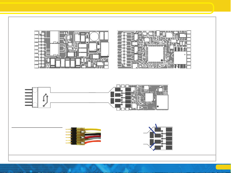
19
Installing the decoder Installing the decoder
pen assignment colour
6 Rear light yellow
5 Front light White
4 Left track connection black
3 Right track connection red
2 Left motor terminal Gray
1 Motor connection right orange
Figure 2: 5 & LokSound LokSound micro 5 with 6-pin interface NEM651
58416 LokSound 5
front
Speaker # 1 Speaker
# 2 -Motoranschluss right
-Gleisanschluss right -
Rear light -U +
(positive pole) -
AUX1 (Power)
light Front
-Gleisanschluss left
-Motoranschluss left -
back
-- AUX8 (Power)
-- AUX7 (Power)
-- AUX6 (Power)
-- AUX5 (Power)
-- AUX4 (Power)
-- AUX 3 (Power)
-- VCC
-- AUX10 / wheel sensor
-- GND
-- AUX9 / PwrPackCtrl
-- U + (+ pole)
AUX9, AUX10 are logic level outputs and inputs
58816 LokSound micro 5
AUX7 is logic level output (Default: PwrPackCtrl)
Motor connection right -----------
---- right track connection
---- AUX1 (Power)
---- U + (+ pole)
---- AUX2 (Power)
---- left track connection
1
6
Light Front -----------
Light rear
speakers # 1
Speaker # 2 left motor
terminal
-- GND
-- U +
AUX9 Default: PwrPackCtrl
GND
-AUX7 -U
+ (+ Pol) -
-- VCC
-- AUX5 (Pwr)
-- AUX6 (Pwr)
-- AUX2
(Power)
20
Installing the decoder
AUX10 / wheel sensor 1
AUX7 (logic levels) 2 AUX6
(logic levels) 3 AUX4 (see
below) 4 AUX12 / SUSI Clk /
Servo6 5 AUX11 / SUSI Dta /
Servo5 6
Rear light Front
light 7 8 speakers # 1
# 2 10 9 Speaker
Indexpin 11
Figure 3: LokSound 5 with 21MTC
22 right track connection 21 left
track connection 20 GND
19 Motor 18 Motor connection
right connecting links 17 AUX5
(logic levels) 16 U + (+ pole) 15 14
AUX1 AUX2
AUX3 13 (see below) 12
VCC
How to connect the:
Insertion of the decoder with
Plug upwards
(Eg Liliput®, ESU, HAG®,
Märklin®)
Insertion of the decoder with
Plug downwardly
(Eg Brawa®)
Crucial indicator
(side view)
Crucial indicator
(side view)
58419 LokSound 5 21MTC 58449
LokSound 5 21MTC "MKL"
---- AUX8 (Power)
---- AUX7 (Power)
---- AUX6 (Power)
---- AUX5 (Power)
---- AUX4 (Power)
---- AUX 3 (Power)
---- VCC
---- AUX10 Logic Level / wheel sensor
---- GND
---- AUX9 Logic Level / PwrPackCtrl
---- U + (+ pole)
For decoder 58449 AUX3, AUX4 at the 21MTC are reinforced. For decoder 58419 AUX3, AUX4 at the 21MTC are
logic level outputs.
AUX9, AUX10 are logic level outputs and inputs AUX11, AUX12
are logic level outputs
1
11
22
AUX9 Default: PwrPackCtrl
This manual suits for next models
15
Table of contents
Other Esu Media Converter manuals

Esu
Esu SignalPilot 51840 User manual

Esu
Esu 51801 User manual

Esu
Esu LokPilot V3.0 User manual

Esu
Esu LokPilot 52600 User manual

Esu
Esu LokSound 5 DCC User manual

Esu
Esu LokSound V3.0 User manual

Esu
Esu LokPilot V4.0 User manual

Esu
Esu LokPilot mfx User manual

Esu
Esu LokPilot V2.0 User manual

Esu
Esu SwitchPilot 3 User manual


