7
IPOD/IPHONE CONNECTOR WITH VIDEO-IN 2 (AV2)
iPod / iPhone Anschluss mit Video-Eingang 2 (AV2)
HANDBRAKE CONNECTION & STEREO INPUT FOR AV2/ AUX
Handbremsen-Anschluss & Stereo-Eingang für AV2/AUX
INSTALLATION NOTES / Installationshinweise
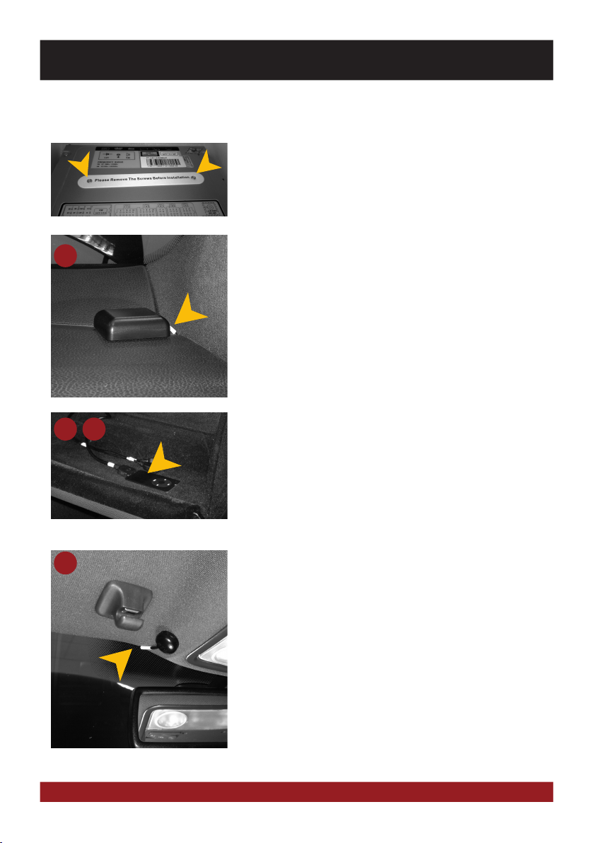
GPS antenna:
The GPS (13) antenna must be mounted horizontally in front on the dashboard
(ensure a clear view to the sky). A metalized windscreen allows no recepti-
on. If a factory GPS antenna with the same connector type (Fakra) is already
available, it can be used. Then the installation of the included GPS antenna is
not necessary.
GPS Antenne:
Die GPS Antenne (13) muss waagerecht, nach Möglichkeit vorne auf dem Ar-
maturenbrett montiert werden (auf freie Sicht zum Himmel achten). Bei einer
metallbedampften Scheibe ist kein Empfang möglich. Falls eine werksseitige
GPS-Antenne mit dem denselben Steckertyp (Fakra) bereits vorhanden ist,
kann diese verwendet werden. Die Installation der beiliegenden GPS Antenne
entfällt.
BT-Microphone:
Mount the supplied microphone (12) at a suitable point such as at the A-pillar
(driver‘s side) or on the roof lining at the interior lamp. Avoid laying the cable
over the steering column. In general, the cable should be long enough to reach
a desired mounting point at the A-pillar (driver‘s side) while laying the cable
over the the passenger‘s side. A possibly existing factory microphone is not
compatible with the ESX device. Please use the supplied microphone.
BT-Mikrofon:
Montieren Sie das beiliegende Mikrofon (12) an einem geeigneten Montage-
punkt wie z.B. an der A-Säule (Fahrerseite) oder am Dachhimmel bei der In-
nenraumleuchte. Vermeiden Sie das Verlegen des Kabels über die Lenksäule.
In der Regel sollte das Kabel lang genug sein, um die A-Säule (Fahrerseite)
über die Beifahrerseite zu erreichen. Ein evtl. werksseitig vorhandenes Mik-
rofon ist nicht kompatibel mit dem ESX Gerät. Bitte verwenden Sie das mit-
gelieferte Mikrofon.
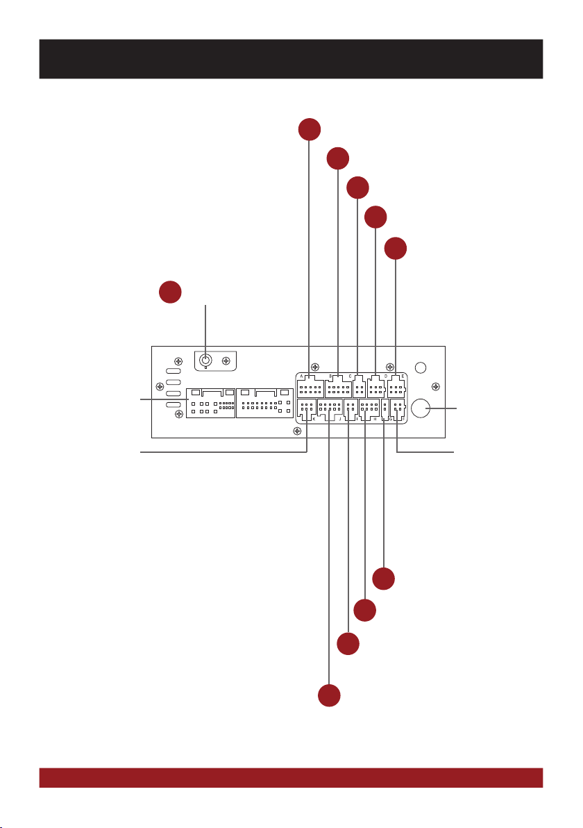
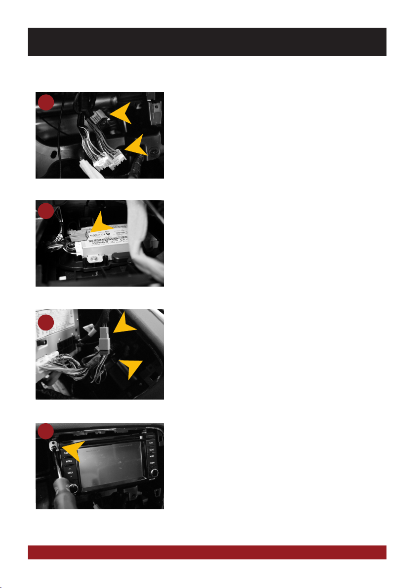
USB/iPod/iPhone Connectors:
Route the cables (10) or (11) to a desired location, such as the glove box. If
necessary, you must drill openings. One of the USB ports needed for the TMC
antenna (15).
USB/iPod/iPhone Anschlüsse:
Verlegen Sie die Kabel (10) oder (11) an den gewünschten Einbauort, wie z.B.
im Handschuhfach. Gegebenenfalls, müssen dafür Öffnungen gebohrt werden.
Einer der USB Anschlüsse wird für die TMC Antenne (15) benötigt.
Einbautipps:
Installation hints:
13
10 11
12
Transportation lock:
Remove both transportation locks on top of the device before you start the
installation.
Transportsicherung:
Entfernen Sie beide Transportsicherungen auf der Oberseite des Geräts, bevor
Sie mit der Installation beginnen.