ETC sensor+ CEM+ User manual

Part Number: 7150M1400-3.1.0 Rev: B
Released: 2021-12
CEM+
User/Configuration Manual
Version 3.1

Table of Contents i
Table of Contents
Introduction. . . . . . . . . . . . . . . . . . . . . . . . .1
Using this Manual. . . . . . . . . . . . . . . . . . . . . . . . . . . . . . . . . . . .1
What’s New in v3.1. . . . . . . . . . . . . . . . . . . . . . . . . . . . . . . . . . .1
Help from ETC Technical Services . . . . . . . . . . . . . . . . .2
Chapter 1
Overview . . . . . . . . . . . . . . . . . . . . . . . . . . .3
System Components . . . . . . . . . . . . . . . . . . . . . . . . . . . . . . . . . .3
Sensor+ Connect Web Browser Interface Overview. . . . . . . . .4
Sensor+ Dimming System Features . . . . . . . . . . . . . . . . . . . . . .5
CEM+ Playback Priorities . . . . . . . . . . . . . . . . . . . . . . . . . . . . . .6
System Limitations . . . . . . . . . . . . . . . . . . . . . . . . . . . . . . . . . . .7
Chapter 2
Basic Navigation . . . . . . . . . . . . . . . . . . . . .9
The CEM+ User Interface . . . . . . . . . . . . . . . . . . . . . . . . . . . . . .9
CEM+ Basic Operation . . . . . . . . . . . . . . . . . . . . . . . . .10
The Default Display . . . . . . . . . . . . . . . . . . . . . . . . . . . . . . . . .10
The Main Menu . . . . . . . . . . . . . . . . . . . . . . . . . . . . . . . . . . . .10
NoConfig . . . . . . . . . . . . . . . . . . . . . . . . . . . . . . . . . . . . . . . . . .11
About . . . . . . . . . . . . . . . . . . . . . . . . . . . . . . . . . . . . . . . . . . . .11
Login . . . . . . . . . . . . . . . . . . . . . . . . . . . . . . . . . . . . . . . . . . . . .12
Dimmer [User][Power] . . . . . . . . . . . . . . . . . . . . . . . . . . . . . . .12
Rack [User][Power] . . . . . . . . . . . . . . . . . . . . . . . . . . . . . . . . . .14
Group [User][Power]. . . . . . . . . . . . . . . . . . . . . . . . . . . . . . . . .18
Chapter 3
Sensor+ Connect Web Interface . . . . . . . .21
Group . . . . . . . . . . . . . . . . . . . . . . . . . . . . . . . . . . . . . .22
Summary Status . . . . . . . . . . . . . . . . . . . . . . . . . . . . . . . . . . . .22
Dimmer Check. . . . . . . . . . . . . . . . . . . . . . . . . . . . . . . . . . . . . .22
Racks & Dimmers . . . . . . . . . . . . . . . . . . . . . . . . . . . . .23
All Racks . . . . . . . . . . . . . . . . . . . . . . . . . . . . . . . . . . . . . . . . . .23
Add Racks . . . . . . . . . . . . . . . . . . . . . . . . . . . . . . . . . . . . . . . . .24
Rack # . . . . . . . . . . . . . . . . . . . . . . . . . . . . . . . . . . . . . . . . . . . .24
Search . . . . . . . . . . . . . . . . . . . . . . . . . . . . . . . . . . . . . . . . . . . .28
Rooms & Presets . . . . . . . . . . . . . . . . . . . . . . . . . . . . . .29
Assign Dimmers . . . . . . . . . . . . . . . . . . . . . . . . . . . . . . . . . . . .29
Room (1-4). . . . . . . . . . . . . . . . . . . . . . . . . . . . . . . . . . . . . . . . .29

ii Sensor+ CEM+ Configuration Manual
Configuration . . . . . . . . . . . . . . . . . . . . . . . . . . . . . . . .31
Panic . . . . . . . . . . . . . . . . . . . . . . . . . . . . . . . . . . . . . . . . . . . . .31
Patch . . . . . . . . . . . . . . . . . . . . . . . . . . . . . . . . . . . . . . . . . . . . .31
Network . . . . . . . . . . . . . . . . . . . . . . . . . . . . . . . . . . . . . . . . . .33
File Transfer . . . . . . . . . . . . . . . . . . . . . . . . . . . . . . . . . . . . . . .34
File Upload . . . . . . . . . . . . . . . . . . . . . . . . . . . . . . . . . . . . . . . .35
Load Management . . . . . . . . . . . . . . . . . . . . . . . . . . . . . . . . . .35
Chapter 4
CEM+ Procedures. . . . . . . . . . . . . . . . . . . .37
CEM+ Configuration Overview . . . . . . . . . . . . . . . . . . . . . . . .37
Configuration Procedures . . . . . . . . . . . . . . . . . . . . . .37
Configure Your Computer for an ETCNet2 Network . . . . . . .37
Software Changes [Power]. . . . . . . . . . . . . . . . . . . . . . . . . . . .38
Delete All Racks [Power] . . . . . . . . . . . . . . . . . . . . . . . . . . . . .39
Build New Configuration (from NoConfig State) . . . .40
Configure/Confirm Network Settings of CEM+ . . . . . . . . . . .40
Add Racks [Power] . . . . . . . . . . . . . . . . . . . . . . . . . . . . . . . . . .41
Port Settings . . . . . . . . . . . . . . . . . . . . . . . . . . . . . . . . . . . . . . .41
Patch . . . . . . . . . . . . . . . . . . . . . . . . . . . . . . . . . . . . . . . . . . . . .42
Set Dimmer Properties . . . . . . . . . . . . . . . . . . . . . . . . . . . . . . .42
Rooms & Presets . . . . . . . . . . . . . . . . . . . . . . . . . . . . . .46
Assign Dimmers to Rooms . . . . . . . . . . . . . . . . . . . . . . . . . . . .46
Create a Preset (Web Only) . . . . . . . . . . . . . . . . . . . . . . . . . . .46
Record vs. Snapshot a Preset . . . . . . . . . . . . . . . . . . . . . . . . . .47
Activate/Deactivate a Preset . . . . . . . . . . . . . . . . . . . . . . . . . .47
Panic . . . . . . . . . . . . . . . . . . . . . . . . . . . . . . . . . . . . . . .47
Record Panic . . . . . . . . . . . . . . . . . . . . . . . . . . . . . . . . . . . . . . .47
Activate Panic . . . . . . . . . . . . . . . . . . . . . . . . . . . . . . . . . . . . . .47
Load Management . . . . . . . . . . . . . . . . . . . . . . . . . . . .48
Record Loads. . . . . . . . . . . . . . . . . . . . . . . . . . . . . . . . . . . . . . .48
Delete Loads (Web Only) . . . . . . . . . . . . . . . . . . . . . . . . . . . . .48
Clear Errors . . . . . . . . . . . . . . . . . . . . . . . . . . . . . . . . . .48
File Transfers. . . . . . . . . . . . . . . . . . . . . . . . . . . . . . . . .49
Download (config from selected IP) . . . . . . . . . . . . . . . . . . . .49
Backup (to all). . . . . . . . . . . . . . . . . . . . . . . . . . . . . . . . . . . . . .49
View a Configuration . . . . . . . . . . . . . . . . . . . . . . . . . . . . . . . .50
Download a Configuration . . . . . . . . . . . . . . . . . . . . . . . . . . .50
Upload a Configuration . . . . . . . . . . . . . . . . . . . . . . . . . . . . . .51
FTP Server . . . . . . . . . . . . . . . . . . . . . . . . . . . . . . . . . . . . . . . . .51
System Maintenance . . . . . . . . . . . . . . . . . . . . . . . . . .52
Replacing a CEM+ Control Module . . . . . . . . . . . . . . . . . . . . .52
Verifying the Configuration of the New Control Module . . .53
Table of Contents iii
Chapter 5
Service . . . . . . . . . . . . . . . . . . . . . . . . . . . .55
Contacting ETC . . . . . . . . . . . . . . . . . . . . . . . . . . . . . . . . . . . . .55
Changing Installation Rack Modules. . . . . . . . . . . . . . . . . . . .55
CEM+ Fuses . . . . . . . . . . . . . . . . . . . . . . . . . . . . . . . . . . . . . . . .58
Troubleshooting . . . . . . . . . . . . . . . . . . . . . . . . . . . . . .59
Make a Preliminary Examination of Your System... . . . . . . . .59
If You Cannot Locate or Correct the Problem... . . . . . . . . . . .59
Appendix A
Basic/Portable Mode . . . . . . . . . . . . . . . . .61
Appendix B
SmartLink Stations Enabled . . . . . . . . . . .63
Features. . . . . . . . . . . . . . . . . . . . . . . . . . . . . . . . . . . . . . . . . . .63
Definitions. . . . . . . . . . . . . . . . . . . . . . . . . . . . . . . . . . . . . . . . .63
Synchronization . . . . . . . . . . . . . . . . . . . . . . . . . . . . . .64
Preset and Sequence Synchronization . . . . . . . . . . . . . . . . . .64
Wall Stations. . . . . . . . . . . . . . . . . . . . . . . . . . . . . . . . .65
Station Options. . . . . . . . . . . . . . . . . . . . . . . . . . . . . . . . . . . . .66
Record a Preset from a Wall Station . . . . . . . . . . . . . .68
Appendix C
Redundant Tracking Backup. . . . . . . . . . .69
Features. . . . . . . . . . . . . . . . . . . . . . . . . . . . . . . . . . . . . . . . . . .69
Hardware . . . . . . . . . . . . . . . . . . . . . . . . . . . . . . . . . . . . . . . . .69
Addressing . . . . . . . . . . . . . . . . . . . . . . . . . . . . . . . . . . . . . . . .70
Configuration . . . . . . . . . . . . . . . . . . . . . . . . . . . . . . . . . . . . . .70
Operation . . . . . . . . . . . . . . . . . . . . . . . . . . . . . . . . . . . . . . . . .70
Appendix D
CEM+ Status Messages . . . . . . . . . . . . . . .71
Appendix E
Dimmer Curves. . . . . . . . . . . . . . . . . . . . . .73
Linear curve. . . . . . . . . . . . . . . . . . . . . . . . . . . . . . . . . . . . . . . .73
Modified linear curve . . . . . . . . . . . . . . . . . . . . . . . . . . . . . . . .74
Square law curve . . . . . . . . . . . . . . . . . . . . . . . . . . . . . . . . . . .74
Modified Square law curve . . . . . . . . . . . . . . . . . . . . . . . . . . .75
Sensor 2.0 curve . . . . . . . . . . . . . . . . . . . . . . . . . . . . . . . . . . . .75

iv Sensor+ CEM+ Configuration Manual
Appendix F
CEM+ LCD Menu . . . . . . . . . . . . . . . . . . . .77
No Config Menu . . . . . . . . . . . . . . . . . . . . . . . . . . . . . . . . . . . .77
About . . . . . . . . . . . . . . . . . . . . . . . . . . . . . . . . . . . . . . . . . . . .78
Dimmers Menu . . . . . . . . . . . . . . . . . . . . . . . . . . . . . . . . . . . . .79
Rack Menu . . . . . . . . . . . . . . . . . . . . . . . . . . . . . . . . . . . . . . . .80
Group Menu . . . . . . . . . . . . . . . . . . . . . . . . . . . . . . . . . . . . . . .82
Appendix G
Sensor+ Connect Site Map . . . . . . . . . . . .85
Appendix H
ACN Reporting. . . . . . . . . . . . . . . . . . . . . .87
About ACN . . . . . . . . . . . . . . . . . . . . . . . . . . . . . . . . . . . . . . . .87
ACN Net3 Reporting. . . . . . . . . . . . . . . . . . . . . . . . . . . . . . . . .87
Configuration Changes . . . . . . . . . . . . . . . . . . . . . . . . . . . . . .88
ACN Control . . . . . . . . . . . . . . . . . . . . . . . . . . . . . . . . . . . . . . .88

Introduction 1
Introduction
Congratulations on your purchase of an ETC Sensor+ system. Sensor+ continues ETC's tradition of
providing the highest quality products for the entertainment lighting market.
Using this Manual
This manual contains information on using and configuring features of the Sensor+ CEM+ in any
Sensor+ rack or pack available up through the Power User login user level.
The following symbols are used in this manual to alert you to danger or important information.
What’s New in v3.1
Here’s a list of changes and new features in v3.1:
• Load High Error increased from 135 VAC to 140 VAC
• AF improvements
- Added “no load alarm”
- No load alarm can be disabled per rack
- Actual loads report without recording loads
- Loads now displayed in Amps
- Load accuracy consistent across all circuits
- Minimum load 300W resistive
• Basic Portable Mode improvements
- Activated DMX B Input
- Added menu for option to change between normal/switched operation per dimmer
- Added menu option to choose single or three phase operation.
Note:
Notes are helpful hints and information that is supplemental to the main text.
CAUTION:
A Caution statement indicates situations where there may be undefined or
unwanted consequences of an action, potential for data loss or an equipment
problem.
WARNING: A Warning statement indicates situations where damage may occur, people
may be harmed, or there are serious or dangerous consequences of an action.
WARNING: RISK OF ELECTRIC SHOCK! This warning statement indicates situations where
there is a risk of electric shock.
Note:
Dimmer output shuts off at 140V. Suggested incoming voltage is 135V or less in
order to allow for line voltage fluctuation.

2Sensor+ CEM+ User/Config Manual
Help from ETC Technical Services
If you are having difficulties, and your problem is not addressed by this document, try the ETC support
website at support.etcconnect.com or the main ETC website at etcconnect.com. If none of these
resources are sufficient, contact ETC Technical Services directly at one of the offices identified below.
Emergency service is available from all ETC offices outside of normal business hours.
When calling for help, take these steps first:
• Your location and job name
• Any error messages on the CEM+ status LCD display
• Related system problems or equipment failures
Note:
For the best service results, always tell your service representative you are using
the CEM+ version of Sensor dimming system.
ETC, Inc.
Americas
Technical Services Department
3031 Pleasant View Road
Middleton, WI 53562
800-775-4382 (USA, toll-free)
+1-608 831-4116
ETC GmbH
Germany, Austria, Switzerland, Eastern
Europe, and Russia
Technical Services Department
Ohmstrasse 3
83607 Holzkirchen, Germany
+49 (80 24) 47 00-0
techserv-germany@etcconnect.com
ETC Austin
High End Systems Products
Technical Services Department
2105 Gracy Farms Lane
Austin, TX 78758 USA
800-890-8989 (USA, toll-free)
+1-512 836-2242
ETC France
France
Zone Urbaparc -
Bâtiment E
6 Boulevard de la Libération
Saint-Denis, 93200
+33 1 4243 3535
ETC Ltd
Europe, Middle East, and Africa
Technical Services Department
26-28 Victoria Industrial Estate
Victoria Road,
London W3 6UU England
+44 (0)20 8896 1000
ETC Asia
Asia
Technical Services Department
Room 1801, 18/F
Tower 1, Phase 1 Enterprise Square
9 Sheung Yuet Road
Kowloon Bay, Kowloon, Hong Kong
+852 2799 1220

Overview 3
Chapter 1
Overview
This manual covers functions and configuration of the CEM+ via the face panel and Sensor+ Connect
interfaces that are available to the Guest, User and Power User login levels.
A Sensor+ dimming system controls lighting using a variety of protocols, including:
• ESTA BSR E1.31, commonly known as 'Streaming ACN'. Streaming ACN provides an industry
standard way of transporting DMX levels over a network. E1.31 is currently a draft standard, and
Sensor+ supports the second draft.
• ETC’s own EDMX control protocol
• Two inputs of USITT DMX512A
• Architectural Presets, controlled by ETC’s SmartLink stations
The configuration of your dimming system determines which input or combination of inputs will
generate the output levels of your dimmers
System Components
The Sensor+ system consists of Sensor+ racks or packs, CEM+ control modules and various dimmer
module types, however a module may contain only a circuit breaker, a relay, or may contain no
electronics at all.
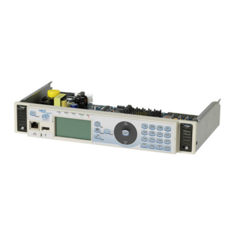
CEM+ Control Module
The CEM+ control module is required for Sensor+ dimming systems - the system will not function
without a properly configured CEM+. This module serves as the real time processor for incoming
control signals and transmits that information to the individual dimmers. It also monitors the system
status and reports any errors. The CEM+ module can be used to configure the system. Configuration
and error data can be accessed either locally at the CEM+ keypad, or by using the Sensor+ Connect
web browser interface.
Networked Sensor+ systems can be split into separately configured subsystems called Groups. Each
configuration can support up to 16 CEM+ modules in a Group. The Group configuration is stored in all
CEM+ modules in that group. A single ETCNet2 network may contain up to 64 Groups (up to 1024
racks total). One exception to these rules are ESR racks which can contain two CEM+s in redundant
tracking mode. In this mode, the number of racks in a Group are limited to 8 racks (still 16 CEM+
modules).
User Level PIN Login Password
Default none Just click “Log On”
Guest none* guest guestpass
User 2222 user userpass
Power User 3333 power
*The face panel no longer has a Guest user level and defaults to User login access.
Rack: 1/ 5 OK
A:001 B:Off

4Sensor+ CEM+ User/Config Manual
The CEM+ has an Ethernet data input for incoming EDMX and sACN data and two DMX512 input
ports (Port A and Port B). DMX Port B can be used as a DMX output port for one universe of DMX on
the last logical rack in the Group. Data management is determined in the Group configuration.
Sensor+ Connect Web Browser Interface Overview
The CEM+ module contains a web server that delivers graphical web pages for you to use during
system configuration. The Sensor+ Connect Web browser interface can be used instead of the direct
buttons on the CEM+ module itself. You can use an Ethernet-capable PC connected to the ETCNet2
network and running Windows 2000 or XP and Internet Explorer 6 or later to browse into any of the
Sensor+ racks on the network.
If you are using an Emphasis Control System running version 1.8.0 software or later, there is a
command in the WYSILink menu that automatically opens a browser window and connects to Sensor+
racks.
Pages need to be manually refreshed by clicking on the refresh button in the upper-right corner of the
webpage. This makes sure you can get up-to-date information when you want it and not wait through
an automatic refresh when you don’t want it.
Sensor+ Connect uses a navigation layout where the various main areas are selected on the left side of
the page presenting sub-options. The right side of the page is used to view or edit the selected
information.
Note:
The Emphasis Server network settings are the default ETC values and ready for
immediate use. No configuration is required.
Logout button
and
user level
Navigation Frame Edit Frame
Edit Tabs
Screen Refresh button

Overview 5
You must set an IP address for any personal computer you plan to use on an ETCNet2 or Net3 network.
ETC recommends that the personal computer used on a lighting network is dedicated to that network
so changes to network settings are kept to a minimum. See
Configure Your Computer for an ETCNet2
Network
on
page 37
for setting up your computer.
Sensor+ Dimming System Features
Play back Presets from the CEM+
The CEM+ module provides 128 Presets that can be recorded from EDMX, sACN, DMX, or directly set
levels. You can configure each Preset’s name, fade times and playback priority. Presets can be assigned
to any one of four Rooms in the configuration. Sensor+ systems can also have the Group play back a
Preset in case of data loss.
Sensor+ Connect for Feedback
Sensor+ Connect duplicates the functions of the CEM+ module on a PC or Net3 console on the lighting
network. The Web browser interface allows you to check rack and dimmer status as well as reconfigure
dimmer curves, record and activate presets, load and backup configurations, and many other features.
Access to the CEM+ and Sensor+ Connect configuration features is protected by specific user levels
and passwords to limit system-altering features to selected personnel, while allowing basic operational
functions to a wider range of users.
Advanced Features
Sensor+ Advanced Features (AF) racks provide additional reporting features that help you to quickly
learn the status of your dimming system and diagnose problems. AF dimmer modules indicate the
presence of data and the relative output of power with LED indicators on the modules themselves.
Much more information can be displayed on the CEM+ module’s integral LCD display or a PC on the
network running Sensor+ Connect in a web browser.
Advanced Features provides the ability to record and monitor individual dimmer loads, provide error
messages such as dimmer removed, SCR fail, breaker trip and other monitoring tools. Constant
comparison of actual dimmer loads against the recorded value lets the system signal you when a load
value changes. The change usually indicates a lamp has burned out or failed, allowing you to make an
immediate replacement.
Dimmer Doubling (60Hz systems only)
ETC’s Dimmer Doubler technology allows you to double the number of controllable circuits in your
system without adding dimmer modules or running additional cable. The key to this feature is the
Dimmer Doubler two-fer.
The Dimmer Doubler two-fer is installed between a Sensor dimmer module and two ETC Source Four
77 volt fixtures. It splits the output of a single dimmer into two, separately-controlled outputs. You can
then use an ETC control console to independently control the output of the two fixtures.
Note:
If the computer you wish to use is currently being used on a non-ETCNet2
network, consult your Network Administrator before changing the IP address,
Subnet Mask, or Gateway IP addresses.
Note:
Sensor+ Connect and Message logging are available on Emphasis Servers as a
base functionality.

6Sensor+ CEM+ User/Config Manual
CEM+ Playback Priorities
The CEM+ uses the ACN priority scheme internally to arbitrate the priorities of each input. It also uses
the priorities directly from the sACN sources if they are provided. This can make for a flexible and
versatile system to meet your needs, but it can also be a bit complex. Refer to the diagram below to
help determine how your CEM+ will use the data in your system as you configure it.
CEM+ Dimmer
Levels
CEM+ Port B
DMX Output
Set Levels
Inputs
Outputs
Arbitration
Engine
Panic/
Emergency
All priorities are arbitrated here to determine which sources & levels win, lose or HTP (Highest Take Precedence or Pile-On) using the 1 (Lo) to 200 (Hi) scale.
DMX B
Input
CEM+ takes the levels
and applies a
user-defined
configuration priority to it.
1 (Low) to 200 (High)
DMX A
Input
CEM+ takes the levels
and applies a
user-defined
configuration priority to it.
1 (Low) to 200 (High)
Presets
CEM+ (per Preset) takes
the levels and applies a
user-defined
configuration priority to it.
1 (Low) to 200 (High)
EDMX
Input
CEM+ takes the
“winner levels” from
network EDMX and
applies a
user-defined
configuration priority
to it internally.
1 (Low) to 200 (High)
EDMX Priorities
Unison (Replace) (0)
Priority 1
.
Priority 20
Unison (PTiA) (21)
0=High to 21 Low
Network EDMX
Level info resolves
before getting to
the CEM+
sACN
Input
CEM+ uses the sACN
priorities from the
network data. If no
priority is given by the
sACN source, the CEM+
applies a user-defined
configuration priority to it
internally.
1 (Low) to 200 (High)
sACN has 2 different
types of priorities. Per
Address Priority and
Per Universe Priority.
Both are supported
by CEM+.
1=Low to 200=High
CEM+ (per rack)
supports up to
6 simultaneous
sACN sources.
The 7th source
is ignored.
CEM+
Set Levels overrides any level information previous to this point.
Panic/Emergency overrides any levels previous to this point.
This is additive unless “Force others off” is enabled.

Overview 7
System Limitations
Group
• Maximum Racks: 16
• Maximum Dimmers: 1536
• DMX Output only from last rack
• DMX output is considered 512 virtual dimmers for maximum dimmer count
• Maximum Presets: 128
• Maximum Rooms: 4
• Maximum Active Presets: 4
• Panic: 1 per group
• UL 924 compliance requires wires to be landed on every emergency rack with normally open,
maintain closure type
Rack
• Voltage Ranges:
- UL 120V 90-135V (Dimmer output turns off if voltage is less than 90V or greater than 140V)
- CE 180-280V (dimmer outputs turn off if voltage is less than 180V or greater than 280V)
• Frequency Range: 47-63 Hz
• Maximum number of sACN sources: 6 (per universe)
• Maximum Number of valid patch universes: 2
For sACN: 4 universes per rack (if last rack, this includes B-out patching)
• Maximum number of ACN subscribers: 12 (for configuration and reporting)
Dimmer
• Maximum number of rooms assigned to: 1
• Dimmer numbers must be unique within a group. Configurations with duplicate dimmer
numbers will be rejected.
General behavior
• Dimmer modes work only as property “defaults” such that you do not have to know how to set
up each dimmer type beyond general function requirements such as “run like a relay” = switch
and “run like a forward phase dimmer” = normal.
• Data loss activates per port type. EDMX and sACN responds to data loss on a per dimmer basis
though DMX responds per port.
SmartLink
• Maximum number of Sensor+ SmartLink power supplies in a SmartLink system: 1 (must be
installed in Rack 1 of group)
• Maximum number of SmartLink control stations on a SmartLink power supply in a group: 4
• Maximum amount of SmartLink enabled products connect to a Sensor+ SmartLink power board:
4 (excluding Sensor Racks and SmartLink stations)
• Maximum number of groups activating presets from a single SmartLink network: 4

8Sensor+ CEM+ User/Config Manual

Basic Navigation 9
Chapter 2
Basic Navigation
This manual covers functions and configuration of
the CEM+ and Sensor+ Connect that are available
to the User and Power User login levels of the full
face panel menu. The Basic/Portable feature set and
menu is covered in
Basic/Portable Mode
on
page 61
.
The CEM+ User Interface
You can access all the menus described in this chapter using the buttons on the face of the CEM+
module. Menus and messages are displayed on the integral 2x20 LCD display.
The CEM+ user interface:
• Use to return to the main menu at any time.
• Use and to scroll through menus and through digits and letters in screens requiring user
input. Pressing while holding or will jump by 100.
• Use to accept settings and to view the error list.
• Use to step back through menus.
• Use to access the Set Levels menu.
• Use to reset the CEM+.
User Level PIN
Default/User None
Power User 3333
??
?
?
Reset
Home
Back
Plus
Set Levels
Minus
Accept

10 Sensor+ CEM+ User/Config Manual
CEM+ Basic Operation
The procedures covered in this section are available to users logged in as User, which requires no
password or PIN, and Power User which does require a password or PIN.
The Default Display
Rack: 1/ 5 OK
A:001 B:Off
Rack: 1/ 5 OK
E:12345 S:1/123
Total number racks in
the configuration
Local rack number
Displays starting
address per port
A= DMX Port A
B= DMX Port B
E= EDMX
S= sACN
Rack status
Port disabled
Note: “” instead of “:” indicates that the port has non-sequential dimmer addressing such as
custom patch for individual dimmers or includes air flow modules (AFM) in a rack
Resting
display
toggles
The Main Menu
The main menu is accessed using the and buttons on the CEM+ face panel. Each of the main
menu items is described in the following pages. Each main menu item contains a number of sub-
menus, each of which is illustrated in each section. To return to the CEM+ resting display (the display
at the top of the diagram to the right), press .
For the full menu structure, see
CEM+ LCD Menu
on
page 77
.
[About]
Rack: xx/xx OK
Rack: xx/xx OK
Rack: xx/xx OK
A:001 B:Off
No Config R__/ 0 G__
[Login]
[Login]
[Dimmers]
[Rack]
[Group]
Rack: xx/xx OK
Rack: xx/xx OK
Rack: xx/xx OK
These menus are
available to User.
These menus are
available to User &
Power User.
This menu appears only
when there is no
configuration in the CEM+.
This menu appears when
there is a configuration in
the CEM+.

Basic Navigation 11
NoConfig
The No Config menu provides a place to make initial base settings and begin to create a configuration
for the local CEM+. The NoConfig menu has no login requirements and anyone has access to these
menu items.
Generate Defaults
The Generate Defaults menu allows you to create an initial configuration for your local rack. You can
set your group and rack numbers along with rack type and dimmer information. However, you can
only add multiple racks of the same type. Additional racks or rack types must be added later via the
Add Racks menu item. For the face panel menu see
Add Rack [Power]
on
page 18
and for the web
interface see
Add Racks
on
page 24
.
• The first menu option within generate defaults allows you to choose between the main
modes of operating feature sets. Options are Full Feature or Basic/Portable. This is a
fundamental configuration mode choice. Basic/Portable mode provides a subset of full
feature functionality for use in simple touring applications. For more info see Basic/
Portable Mode on page 61.
• Rack Types: SRxx is the U.S. style perminent installation rack and SPxx is the U.S.
style type of portable rack (including touring racks). ESRxx and ESPxx are for
European installation racks and portable racks respectively. In all cases, the “xx”
number is determined by the number of slots in the rack for modules (not the number
of dimmers).
Set Group/Rack/Net
The Set Group / Rack menu allows you to set the rack number of your local rack and the group number
it belongs to. It also provides a place to set the network information (IP address, subnet mask and
gateway IP). This should be done before creating a configuration. Changing this information may
require the CEM+ to reboot to take effect.
Get Config From
After selecting this function, you will be prompted with the name of the rack you want to get the
configuration from.
Options will include:
•Racks [1-16] which refers to any of the other racks that may be online and configured as being
from the same group.
•FTP Server which refers to an FTP server if one is configured on your lighting network. It will ask
you to specify the server’s IP address. See the section
FTP Server
on
page 51
for more information
about setting up an FTP server for use with CEM+.
•Backplane (Stored in Rack) which refers to the configuration information stored in the back plane
of the local rack.
Once the configuration source has been chosen, it will transfer the configuration to the local CEM+.
After the transfer is complete, you will get a confirmation or error message for the transfer.
About
The About menu provides status information about the dimmers, racks, network and Group.
Everything in the About menu is accessible by all users. No settings can be changed within the About
menu. Data can only be viewed.

12 Sensor+ CEM+ User/Config Manual
Dimmer
About Dimmer provides information about a selected dimmer, including recorded and actual loads, the
dimmer type, curve and maximum voltage. You can also view the current output level, the source of
that level, and the dimmer’s location.
Rack General
The Rack General menu provides the current ambient temperature and air flow status of the selected
rack. It also displays the rack type, the air filter cleaning reminder setting, and the number of hours
until the air filter cleaning reminder is due.
Network
About Network provides the network settings for the currently selected rack. You can view the settings
for any rack in the Group.
Rack Data Ports
About Rack Data provides status information for the DMX, EDMX and sACN inputs for any rack in the
Group.
Rack Power
About Rack Power provides status information for the line feed power and the voltage headroom
settings for any rack in the Group.
Identify Rack
Identify Rack flashes the LCD and buttons on the face panel of the selected rack.
Group
About Group provides the name set for the Group.
About Software
Provides the software version currently installed in the racks.
Login
The Login menu is where you enter the PIN number for the user level you want to access. User level
needs no PIN to view the menu items accessible to them. You will need to enter a four-digit PIN to gain
access to features that are restricted to higher user levels. Enter the default PIN of 3333 to gain Power
User level access. Use and to scroll the digits and use to enter the set digit.
Dimmer [User][Power]
The Dimmer menu allows you access to setting and releasing dimmer levels, and Power allows access to less commonly accessed features such as renaming of
racks and dimmers as well as higher level module setup items such as setting the scale and preheat properties, advanced feature settings, and deleting the
configuration.
Set/Release Levels
The Set Levels menu allows you to set (or release) a dimmer or a range of dimmers to a specified level
at the CEM+. Levels set here take priority over any other level inputs, such as control consoles and
architectural control systems. Once released, those dimmers are available to other control inputs.
Levels set here do not take priority over levels generated by an active Panic look.
The button on the CEM+ face panel accesses this menu directly.
Note:
Power User PIN can be modified for security purposes if required. See Set PIN [Power]
on page 20.

Basic Navigation 13
Setup Dimmer
Set Firing Mode
The Set Firing Mode menu allows you to set a dimmer or a range of dimmers to a specific firing mode.
Available modes include Normal, Off, Switched, Fluorescent, Reverse Phase, and DD (Dimmer
Doubled).
Dimmer firing modes:
• Off: turns the dimmer off.
• Normal: operates as a standard incandescent dimmer.
• Switched: dimmers output unregulated AC voltage when the control level is above the threshold
level.
• DD (Dimmer Doubled) (60Hz systems only): dimmer operates as two controllable circuits. See
Dimmer Doubling (60Hz systems only)
on
page 5
.
Set Curve
The Set Curve menu allows you to set a dimmer or a range of dimmers to a specific curve. A dimmer
curve is a mathematical function that maps control levels to RMS output voltage. Curves are scaled
from the minimum voltage to the maximum voltage (settings that are not available to the User login).
The CEM+ supports the following curves: Square, Mod Square, Linear, Mod Linear, Sensor 2.0. See
Dimmer Curves
on
page 73
, for more information.
Scale & Preheat [Power]
The Scale & Preheat menu allows you to set Voltage Regulation, Dynamic Preheat, DC Output Prevent
and Inrush Settings for a dimmer or range of dimmers.
• Max Scale Voltage: set a dimmer or a range of dimmers to a maximum output voltage that is the
top (100% control) of the scaled output of that dimmer.
• Min Scale Voltage: set a dimmer or a range of dimmers to a minimum output voltage that is the
bottom (1% control) of the scaled output of that dimmer. The dimmer will switch on to an RMS
output voltage of Min Scale Voltage when the control level reaches the value set for threshold.
• Set Threshold: set a dimmer or a range of dimmers to a specific control level at which it begins
to respond. Below that level, the dimmer will remain off.
• Dynamic Preheat: this setting allows quick blackouts on dimmers that are set to preheat.
• Voltage Regulation: when enabled, the dimmer will regulate to the desired output voltage. When
disabled, the dimmer will be set to a constant firing time based on the control level. This setting
defaults “on”. The ability to disable regulation is sometimes useful when dimming non-tungsten
loads.
• Inrush Protection: this setting protects against large voltage increases in a single AC cycle. This
protection is useful for high-wattage loads that may cause nuisance tripping of circuit breakers
and to limit peak currents in wiring and switch gear. This protection is particularly useful on RCD/
GFCI protected circuits.
• DC Output Prevent: this setting offers protection on selected dimmers for loads that are sensitive
to DC buildup, which can occur under certain conditions when positive and negative half-cycles
become uneven.
• Scale Load: This setting adjusts the choke correction curve based on the specified percent load of
the maximum for that dimmer type. Scale Load can be set from 1% to 100% and should reflect
the approximate percent load on a given dimmer to precisely match all dimmed load. The default
setting is 35% which is based on a single Source Four 750 W fixture on a D20 dimmer with a max
scale voltage of 115 VAC.
Note:
Changing the dimmer firing mode will force the default settings for curve, minimum
voltage, maximum voltage, threshold and regulation. Whenever a dimmer mode
is set the defaults for that mode will be applied to the other dimmer properties.

14 Sensor+ CEM+ User/Config Manual
Advanced Features [Power]
The Advanced Features menu allows you to set Advanced Features (on/off), Report Load Errors, AF
Sensitivity, and AF Reaction Time for a dimmer or range of dimmers.
• Advanced Features (on/off): additional feedback from a dimmer that provides load recording/
reporting and advanced error reporting including a breaker trip, module removed, load changes,
dc output and SCR failures.
• Report Load Errors (on/off): allows for messages to report load changes once initial loads have
been recorded for a dimmer.
• AF Sensitivity (1 to 10): defines the resolution of the Advanced Features sensitivity in reporting
load changes. One (1) is the most sensitive/highest resolution setting and the default is 5. AF
sensitivity is based on a percentage of the recorded load.
• AF Reaction Time (5 to 60 seconds): this setting defines the hysteresis for an Advanced Feature
error. The error must be present for the minimum set in the AF Reaction Time before an error will
be reported.
Assign Dim to Room [Power]
The Assign Dimmer to a Room menu allows you to set a dimmer or a range of dimmers to a specific
room for use with recording presets. A dimmer can only be assigned to a single room at a time. There
are four (4) rooms available and all dimmers default to being assigned to Room 1.
Set Dimmer Name [Power]
The Set Name menu allows you to name a dimmer. Names are alphanumeric and can be up to 20
characters long (not all 20 characters will be visible on the LCD).
Dimmer Check
The Dimmer Check menu allows you to set an output level and then step through dimmers at a
selected starting point.
Rack [User][Power]
The Rack menu includes menus for setting the rack name and patch settings. The Rack menu is partially
available to those logged in at the User and complete to those logged in at the Power User level.
Patch
The Set Patch menu allows you to enable and disable DMX, EDMX and sACN inputs, set their priority
and create the patch for those input ports. Patching is more abstract than simply turning a function on
and off. There are different methods try to simplify this process for you by matching a method with
your intent.
There are three methods to create or modify the patch from the face panel.
By Start Address
This method allows you to pick a rack, pick
the port (DMX A, DMX B, EDMX or sACN)
then a starting address. That starting
address is used to sequentially address the rest of the dimmers in that rack for that port. If you are
patching DMX A, there is a provision built-in to accommodate crossing over to DMX B after running
out of addresses on DMX A. (This typically happens in larger systems on the 6th SR48 rack) This is the
simplest way to setup addressing for a dimmer rack.
Rack> 1< [DMXA]
Start [xxx]
Patch Dimmers
[by Start Address]
Select Rack 1/ 1
[Nnnnnnnnnnnnnnnn]
Other manuals for sensor+ CEM+
2
Table of contents
Other ETC Control System manuals

ETC
ETC QuickTouch+ 4 User manual

ETC
ETC Rover User manual

ETC
ETC Echo Inspire Station Operating instructions

ETC
ETC Echo User manual

ETC
ETC Eos Apex 5 User manual

ETC
ETC Expression Show Control System User manual

ETC
ETC Emphasis Lighting Control System User manual

ETC
ETC CEM3 User manual

ETC
ETC Obsession II User manual

ETC
ETC sensor+ CEM+ Instruction sheet

ETC
ETC Cem 3 User manual

ETC
ETC Unison User manual

ETC
ETC Sensor3 CEM3 User manual

ETC
ETC Emphasis Lighting Control System User manual

ETC
ETC Obsession II User manual

ETC
ETC IRIDEON User manual

ETC
ETC EUTRAC Technical manual

ETC
ETC Gio User manual

ETC
ETC Response Mk2 One-Port Instruction sheet

ETC
ETC EOS User manual