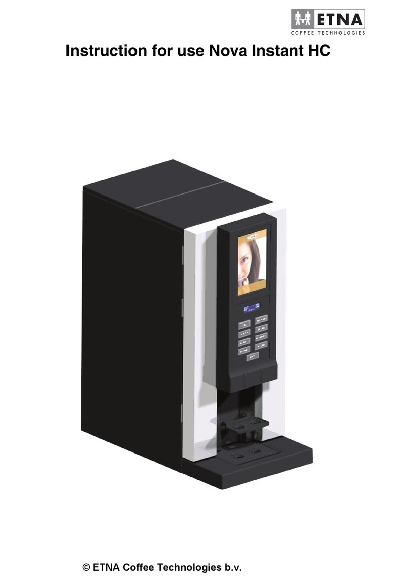
ETNA LP 14 User manual

© ETNA Vending Technologies b.v.
Technical manual LP 14

Technical manual LP 14
Manufacturer: ETNA Vending Technologies b.v.
P.O. Box 200
7130 AE Lichtenvoorde
The Netherlands
Distributor:
© ETNA Vending Technologies b.v.
Articlecode: 966944001
Status: 3
Revision: 2

Technical manual LP 14
3
© ETNA Vending Technologies b.v.
1 INTRODUCTION . . . . . . . . . . . . . . . . . . . . . . . . . . . . . . . . . . . . . . . . . . . . . . . . . . . . . . . . . . . . . . . . . . 5
2 SAFETY . . . . . . . . . . . . . . . . . . . . . . . . . . . . . . . . . . . . . . . . . . . . . . . . . . . . . . . . . . . . . . . . . . . . . . . . . 6
3 CONTAINER LAYOUT. . . . . . . . . . . . . . . . . . . . . . . . . . . . . . . . . . . . . . . . . . . . . . . . . . . . . . . . . . . . . . 7
4 DESCRIPTION OF PRINTED CIRCUIT BOARDS . . . . . . . . . . . . . . . . . . . . . . . . . . . . . . . . . . . . . . . . 8
4.1 General specifications . . . . . . . . . . . . . . . . . . . . . . . . . . . . . . . . . . . . . . . . . . . . . . . . . . . . . . . . . 8
4.2 Control PCB . . . . . . . . . . . . . . . . . . . . . . . . . . . . . . . . . . . . . . . . . . . . . . . . . . . . . . . . . . . . . . . . . 8
4.2.1 COIN MECHANISM SOFTWARE: CON 1 . . . . . . . . . . . . . . . . . . . . . . . . . . . . . . . . . . . . 9
4.2.2 COIN MECHANISM CONNECTION: CON 2 . . . . . . . . . . . . . . . . . . . . . . . . . . . . . . . . . . 9
4.2.3 CONTROL PCB SOFTWARE: CON 3 . . . . . . . . . . . . . . . . . . . . . . . . . . . . . . . . . . . . . . . 9
4.2.4 NOT IN USE: CON 4. . . . . . . . . . . . . . . . . . . . . . . . . . . . . . . . . . . . . . . . . . . . . . . . . . . . . 9
4.2.5 24V POWER SUPPLY PCB: CON 5. . . . . . . . . . . . . . . . . . . . . . . . . . . . . . . . . . . . . . . . 10
4.2.6 DISPLAY PCB: CON 6 . . . . . . . . . . . . . . . . . . . . . . . . . . . . . . . . . . . . . . . . . . . . . . . . . . 10
4.2.7 COIN MECHANISM: CON 7 . . . . . . . . . . . . . . . . . . . . . . . . . . . . . . . . . . . . . . . . . . . . . . 10
4.2.8 OUTPUT TO VARIOUS MOTORS: CON 8. . . . . . . . . . . . . . . . . . . . . . . . . . . . . . . . . . . 10
4.2.9 INPUT SIGNALS: CON 9 . . . . . . . . . . . . . . . . . . . . . . . . . . . . . . . . . . . . . . . . . . . . . . . . 11
4.2.10 CONNECTION TO OUTPUT PCB: CON 10. . . . . . . . . . . . . . . . . . . . . . . . . . . . . . . . . . 12
4.2.11 FUSE ON CONTROL PCB . . . . . . . . . . . . . . . . . . . . . . . . . . . . . . . . . . . . . . . . . . . . . . . 12
4.3 Power supply PCB . . . . . . . . . . . . . . . . . . . . . . . . . . . . . . . . . . . . . . . . . . . . . . . . . . . . . . . . . . . 12
4.3.1 230V FROM POWER SUPPLY PCB: TB1 . . . . . . . . . . . . . . . . . . . . . . . . . . . . . . . . . . . 13
4.3.2 24V TO CONTROL PCB AND OUTPUT PCB: TB 2. . . . . . . . . . . . . . . . . . . . . . . . . . . . 13
4.3.3 FUSE ON POWER SUPPLY PCB . . . . . . . . . . . . . . . . . . . . . . . . . . . . . . . . . . . . . . . . . 13
4.4 Display PCB . . . . . . . . . . . . . . . . . . . . . . . . . . . . . . . . . . . . . . . . . . . . . . . . . . . . . . . . . . . . . . . . 13
4.4.1 CONNECTION TO CONTROL PCB: CON 1 . . . . . . . . . . . . . . . . . . . . . . . . . . . . . . . . . 14
4.4.2 DISPLAY SOFTWARE: CON 2. . . . . . . . . . . . . . . . . . . . . . . . . . . . . . . . . . . . . . . . . . . . 14
4.4.3 COIN MECHANISM CONNECTION: CON 3 . . . . . . . . . . . . . . . . . . . . . . . . . . . . . . . . . 14
4.4.4 SELECTION PANEL: CON 4 . . . . . . . . . . . . . . . . . . . . . . . . . . . . . . . . . . . . . . . . . . . . . 14
4.4.5 SERVICE PANEL: CON 5. . . . . . . . . . . . . . . . . . . . . . . . . . . . . . . . . . . . . . . . . . . . . . . . 14
4.4.6 LCD DISPLAY: CON 6 . . . . . . . . . . . . . . . . . . . . . . . . . . . . . . . . . . . . . . . . . . . . . . . . . . 15
4.4.7 BATTERY: DISPLAY PCB . . . . . . . . . . . . . . . . . . . . . . . . . . . . . . . . . . . . . . . . . . . . . . . 15
4.5 Output PCB . . . . . . . . . . . . . . . . . . . . . . . . . . . . . . . . . . . . . . . . . . . . . . . . . . . . . . . . . . . . . . . . . 15
4.5.1 BOILERS: CON 1 . . . . . . . . . . . . . . . . . . . . . . . . . . . . . . . . . . . . . . . . . . . . . . . . . . . . . . 15
4.5.2 230V INPUT AND OUTPUT: CON 2. . . . . . . . . . . . . . . . . . . . . . . . . . . . . . . . . . . . . . . . 15
4.5.3 230V COMPONENTS: CON 3 . . . . . . . . . . . . . . . . . . . . . . . . . . . . . . . . . . . . . . . . . . . . 15
4.5.4 CONNECTION TO CONTROL PCB: CON 4 . . . . . . . . . . . . . . . . . . . . . . . . . . . . . . . . . 16
4.5.5 FUSES ON OUTPUT PCB . . . . . . . . . . . . . . . . . . . . . . . . . . . . . . . . . . . . . . . . . . . . . . . 16
5 SERVICE AND PROGRAMMING . . . . . . . . . . . . . . . . . . . . . . . . . . . . . . . . . . . . . . . . . . . . . . . . . . . .17
5.1 Installing the machine . . . . . . . . . . . . . . . . . . . . . . . . . . . . . . . . . . . . . . . . . . . . . . . . . . . . . . . . 17
5.1.1 REMOVING WATER FROM THE MACHINE . . . . . . . . . . . . . . . . . . . . . . . . . . . . . . . . . 19
5.1.2 MACHINE TYPE . . . . . . . . . . . . . . . . . . . . . . . . . . . . . . . . . . . . . . . . . . . . . . . . . . . . . . . 19
5.1.3 “NO BEANS” FUNCTION . . . . . . . . . . . . . . . . . . . . . . . . . . . . . . . . . . . . . . . . . . . . . . . . 20
5.1.4 DE-SCALING FUNCTION. . . . . . . . . . . . . . . . . . . . . . . . . . . . . . . . . . . . . . . . . . . . . . . . 20
5.2 Service Panel: user mode . . . . . . . . . . . . . . . . . . . . . . . . . . . . . . . . . . . . . . . . . . . . . . . . . . . . . 21
5.2.1 READING THE CONSUMPTION COUNTERS. . . . . . . . . . . . . . . . . . . . . . . . . . . . . . . . 21
5.2.2 RINSING THE MIXER. . . . . . . . . . . . . . . . . . . . . . . . . . . . . . . . . . . . . . . . . . . . . . . . . . . 21
5.2.3 RINSING THE BREWER . . . . . . . . . . . . . . . . . . . . . . . . . . . . . . . . . . . . . . . . . . . . . . . . 22
5.2.4 CLOCK FOR AUTOMATIC RINSING . . . . . . . . . . . . . . . . . . . . . . . . . . . . . . . . . . . . . . . 22
5.2.5 CLEANING THE BREWER. . . . . . . . . . . . . . . . . . . . . . . . . . . . . . . . . . . . . . . . . . . . . . . 23
5.2.6 RESETTING THE WASTE BUCKET COUNTER . . . . . . . . . . . . . . . . . . . . . . . . . . . . . . 23
5.2.7 MESSAGE TO FILL CONTAINER . . . . . . . . . . . . . . . . . . . . . . . . . . . . . . . . . . . . . . . . . 24
5.3 Service mode . . . . . . . . . . . . . . . . . . . . . . . . . . . . . . . . . . . . . . . . . . . . . . . . . . . . . . . . . . . . . . . 24
5.3.1 DRINK SETTINGS . . . . . . . . . . . . . . . . . . . . . . . . . . . . . . . . . . . . . . . . . . . . . . . . . . . . .25
5.3.1.1 Access to service menu: water volume . . . . . . . . . . . . . . . . . . . . . . . . . . . . . . . 26
5.3.1.2 Adjust/test ingredient dosing . . . . . . . . . . . . . . . . . . . . . . . . . . . . . . . . . . . . . . . 27
5.3.2 STANDARD RECIPES . . . . . . . . . . . . . . . . . . . . . . . . . . . . . . . . . . . . . . . . . . . . . . . . . . 27

4© ETNA Vending Technologies b.v.
Technical manual LP 14
5.3.2.1 Allocating recipes. . . . . . . . . . . . . . . . . . . . . . . . . . . . . . . . . . . . . . . . . . . . . . . . 28
5.3.3 RESETTING DRINK COUNTERS. . . . . . . . . . . . . . . . . . . . . . . . . . . . . . . . . . . . . . . . . . 28
5.3.4 READING THE MACHINE COUNTERS. . . . . . . . . . . . . . . . . . . . . . . . . . . . . . . . . . . . . 29
5.3.5 TYPE OF COIN MECHANISM . . . . . . . . . . . . . . . . . . . . . . . . . . . . . . . . . . . . . . . . . . . . 30
5.3.5.1 Setting the coin values. . . . . . . . . . . . . . . . . . . . . . . . . . . . . . . . . . . . . . . . . . . . 31
5.3.6 SETTING THE TIME AND DATE . . . . . . . . . . . . . . . . . . . . . . . . . . . . . . . . . . . . . . . . . . 32
5.3.7 SETTING THE TEMPERATURE. . . . . . . . . . . . . . . . . . . . . . . . . . . . . . . . . . . . . . . . . . . 33
5.3.8 ENTERING/CHANGING THE PIN CODE. . . . . . . . . . . . . . . . . . . . . . . . . . . . . . . . . . . . 33
6 ERROR CODES AND REPORTS . . . . . . . . . . . . . . . . . . . . . . . . . . . . . . . . . . . . . . . . . . . . . . . . . . . .35
7 LP 14 CONTAINER LAY-OUT. . . . . . . . . . . . . . . . . . . . . . . . . . . . . . . . . . . . . . . . . . . . . . . . . . . . . . . 38
7.1 Container lay-out LP 14 . . . . . . . . . . . . . . . . . . . . . . . . . . . . . . . . . . . . . . . . . . . . . . . . . . . . . . . 38
8 CIRCUIT DIAGRAMS. . . . . . . . . . . . . . . . . . . . . . . . . . . . . . . . . . . . . . . . . . . . . . . . . . . . . . . . . . . . . . 39
8.1 LP 14 CIRCUIT DIAGRAM . . . . . . . . . . . . . . . . . . . . . . . . . . . . . . . . . . . . . . . . . . . . . . . . . . . . . 39

Technical manual LP 14
5
© ETNA Vending Technologies b.v.
1 INTRODUCTION
This technical manual describes the LP 14. It contains a description of the electronics and the
software.
This manual is a reference document for maintenance personnel and operators who need to
change settings on the machines or carry out repairs. See "User instructions" for more
information regarding the installation or use of the LP 14.
➭Store this manual in a safe place. If you have any further questions,
contact the technical maintenance department at ETNA Vending
Technologies b.v..
Technical maintenance department: +31 (0) 544 391 222.
Chapter 2
describes the safety instructions The printed circuit boards are described in
chapter 4
The various service panel functions are described in
chapter 5
.
Chapter 6
contains a summary of
fault codes and reports.

6© ETNA Vending Technologies b.v.
Technical manual LP 14
2SAFETY
The LP 14 meets the requirements in respect of the CE mark.
The following symbols are used in this technical manual:
Indicates: caution, risk of personal injury.
ᏘIndicates: caution, may cause damage to the machine.
☞Indicates: important information.
➭Indicates: tip.
If you are performing repairs on or making modifications to electronic components, you must
observe the safety instructions below. Neither the manufacturer nor the supplier will be held liable
for injury occurring as a result of failure to comply with these instructions.
Note
• When performing repairs on the machine, you must remove the
service key and disconnect the machine from the power supply.
ᏘWarning
• The electronic components in these machines are sensitive to
static electricity. Therefore, the maintenance engineer must always
wear an earthed wrist band when carrying out maintenance on
electronic components.
• Do not excessive amounts water when cleaning the machine.
• Comply with the applicable local regulations when connecting the
equipment to the water and electricity supplies.
☞Note
• When returning printed circuit boards to the factory for repair, they
must always be packed in anti-static packaging.
• No adjustments or modifications may be made to the machine
without written approval from ETNA Vending Technologies b.v.

Technical manual LP 14
7
© ETNA Vending Technologies b.v.
3 CONTAINER LAYOUT
The LP 14 container layout is specified in
appendix 7
.

8© ETNA Vending Technologies b.v.
Technical manual LP 14
4 DESCRIPTION OF PRINTED CIRCUIT BOARDS
The electronic printed circuit boards and general system specifications are described in this
chapter.
The electronic printed circuit boards consist of four printed circuits.
1. The control PCB: the main controller
(see paragraph 4.2)
.
2. The power supply PCB: 24V for the control PCB
(see paragraph 4.3)
.
3. The display PCB: includes the user interface
(see paragraph 4.4)
.
4. The output PCB: the output relay
(see paragraph 4.5)
.
4.1 General specifications
The general specifications of the LP 14 are shown in
table 4-1
.
Table 4-1 General specification of the LP 14
4.2 Control PCB
The control PCB is the most important electronic component. It has ten connectors. The function
of each connector is described in the following paragraphs.
All connectors have a unique code. The coding system for the control PCB connectors is Con x,
where "Con" stands for connector and "x" is a unique number.
Figure 4-1
shows layout of the control PCB.
Power supply
voltage 230 V AC +/- 10%
frequency 50 Hz +/- 2%
Total power consumption (machine) 2700 W
Maximum power consumption (electronic
components) 18 W
Operating temperature + 10 ºC tot + 60 ºC
Storage temperature - 10 ºC tot + 50 ºC

Technical manual LP 14
9
© ETNA Vending Technologies b.v.
Figure 4-1 Control PCB
4.2.1 COIN MECHANISM SOFTWARE: CON 1
The CON 1 connector is used to modify the coin mechanism control software.
4.2.2 COIN MECHANISM CONNECTION: CON 2
The CON 2 connector is used to connect an electronic coin mechanism.
☞The coin mechanism type can be selected in the service mode
(see
paragraph 5.3.5)
.
➭ETNA Vending Technologies b.v. can supply installation kits for the
coinmechanism.
4.2.3 CONTROL PCB SOFTWARE: CON 3
The CON 3 connector is used to modify the control PCB software.
4.2.4 NOT IN USE: CON 4
The CON 4 connector is not in use.

10 © ETNA Vending Technologies b.v.
Technical manual LP 14
4.2.5 24V POWER SUPPLY PCB: CON 5
The CON 5 connector is used to connect the 24V DC power supply from the power supply PCB.
4.2.6 DISPLAY PCB: CON 6
The control PCB is connected to the display PCB by a flat cable between con 6 (control PCB)
and con 1 (display PCB).
4.2.7 COIN MECHANISM: CON 7
The CON 7 connector is used to connect an executive protocol or MDB type coin mechanism.
☞ETNA Vending Technologies b.v. is able to supply the interface cable for
connecting a coin mechanism.
4.2.8 OUTPUT TO VARIOUS MOTORS: CON 8
The water outlet valves, brewer, mixer and the ingredient motors are connected to CON 8.
The CON 8 connector is labelled as follows:
Table 4-2 Overview of CON 8 connections
Pin code Function Cable colour
1 brewer motor 12V DC blue
2 water outlet valve common red
3 water outlet valve 2 pink
4- -
5 ingredient 1 yellow
6- -
7 mixer black
8- -
9 ingredient 2 black
10 -
outputs
110
2011

Technical manual LP 14
11
© ETNA Vending Technologies b.v.
4.2.9 INPUT SIGNALS: CON 9
The drip tray sensor, flow meter, encoder and temperature sensors are connected to CON 9.
The CON 9 connector is labelled as follows:
Table 4-3 Overview of CON 9 connections
11 brewer motor 12V DC purple
12 water outlet valve 1 grey
13 water outlet valve 3 green
14 ingredient 1 black
15 ingredient 2 orange
16 - -
17 mixer blue
18 - -
19 - -
20 - -
Pin code Function Cable colour
1flowmeter+ red
2flowmeter grey
3 encoder - black
4 - -
5 - -
6- -
7 drip tray sensor blue
8 temperature sensor 1 yellow
Pin code Function Cable colour
1
10
9
18
con9

12 © ETNA Vending Technologies b.v.
Technical manual LP 14
4.2.10 CONNECTION TO OUTPUT PCB: CON 10
The control PCB is connected to the output PCB by acable between CON 10 (control PCB)and
CON 4 (output PCB).
4.2.11 FUSE ON CONTROL PCB
There is a fuse on the control PCB that has the following function:
• F1: fuse on the 24V power cable: 8.0 A T/250 V~slow blow.
4.3 Power supply PCB
The power supply PCB converts 230V AC to 24V DC for the control PCB.
9 temperature sensor 1 yellow
10 flow meter - grey
11 encoder + red
12 encoder black
13 - -
14 - -
15 - -
16 drip tray sensor orange
17 temperature sensor 2 grey
18 temperature sensor 2 grey
Pin code Function Cable colour

Technical manual LP 14
13
© ETNA Vending Technologies b.v.
Figure 4-2 Power supply PCB
4.3.1 230V FROM POWER SUPPLY PCB: TB1
The power supply PCB receives 230V from the control PCB via a cable between connector TB1
(power supply PCB) and connector CON 2 (control PCB).
4.3.2 24V TO CONTROL PCB AND OUTPUT PCB: TB 2
The power supply PCB supplies 24V DC to the control PCB and output PCB via a cable between
connector TB 2 (power supply PCB) and connector CON 10 A/B (control PCB) and connector
OP03 (output PCB).
4.3.3 FUSE ON POWER SUPPLY PCB
There is a fuse on the power supply PCB that has the following function:
• F1: fuse on the 230V power cable: 3.15 A T/250 V~slow blow.
4.4 Display PCB
The display PCB forms a link between the selection panel, the service panel and the control
PCB. The display PCB, together with the selection panel and the service panel, form the
interface between the user and the control PCB.
Figure 4-3
shows the layout of the display PCB.

14 © ETNA Vending Technologies b.v.
Technical manual LP 14
Figure 4-3 Display PCB
4.4.1 CONNECTION TO CONTROL PCB: CON 1
The display PCB is connected to the control PCB by aflat cable between CON 1 (display PCB)
and CON 6(control PCB).
4.4.2 DISPLAY SOFTWARE: CON 2
The CON 2 connector is used to modify the display PCB software.
4.4.3 COIN MECHANISM CONNECTION: CON 3
The CON 3 connector is used to connect an electronic coin mechanism.
☞The coin mechanism type can be selected in service mode
(see
paragraph 5.3.5)
.
➭ETNA Vending Technologies b.v. can supply installation kits for the
coinmechanism.
4.4.4 SELECTION PANEL: CON 4
The CON 4 connector is used to connect a selection panel.
4.4.5 SERVICE PANEL: CON 5
The CON 5 connector is used to connect a service panel.

Technical manual LP 14
15
© ETNA Vending Technologies b.v.
4.4.6 LCD DISPLAY: CON 6
The CON 6 connector is used to connect the LCD display.
4.4.7 BATTERY: DISPLAY PCB
This battery is used to retain the set time when the machine is switched off.
4.5 Output PCB
The 230V components are connected to the expansion PCB.
Figure 4-4
shows the layout of the
expansion PCB.
Figure 4-4 Output PCB
4.5.1 BOILERS: CON 1
The boilers are connected to the CON 1 connector.
4.5.2 230V INPUT AND OUTPUT: CON 2
The 230V input and output is connected to the CON 2 connector.
The 230V output is connected to the TB 1 connector on the power supply PCB.
4.5.3 230V COMPONENTS: CON 3
A number of components are connected to the CON 3 connector.

16 © ETNA Vending Technologies b.v.
Technical manual LP 14
The CON 3 connector is labelled as follows:
4.5.4 CONNECTION TO CONTROL PCB: CON 4
The output PCB is connected to the control PCB by acable between CON 4 (output PCB)and
CON 10 (control PCB).
4.5.5 FUSES ON OUTPUT PCB
There are four fuses on the output PCB that have the following function:
• F1: fuse on the power cable to boiler no. 1: 6.3 A T/250 V~slow blow.
• F2: fuse on the power cable to boiler no. 2: 6.3 A T/250 V~slow blow.
• F3: fuse on the power supply cable : 4 A T/250 V~slow blow.
• F4: fuse on power cable to the relay: 4 A T/250 V~slow blow.
Pin code Function Cable colour
1 the common wire black
2 water inlet valve, 230V orange
3 outflow, 230V purple
4 water pump 1, 230V grey
5 water pump 2, 230V pink
6 grinder 1, 230V DC grey
7 grinder 1, 230V DC yellow
8 grinder 2, 230V DC blue
9 grinder 2, 230V DC red
19con3
output

Technical manual LP 14
17
© ETNA Vending Technologies b.v.
5 SERVICE AND PROGRAMMING
The service panel has a different function in each mode. Installation mode
(see chapter 5.1)
,
operating mode
(see chapter 5.2)
and service mode
(see chapter 5.3)
are discussed in the
following paragraphs.
Faults may occur if the incorrect settings are used.
ᏘWhen you insert the service key, the power supply to the machine is
switched on.
➭Functions of the buttons
The 0button on the service panel opens the menu, closes the menu item
and saves the settings. The pin code “123” must be entered within 3
seconds after the 0 .
The beverage button of your choice or button 4on the service panel
enables you to scroll through the menus from top to bottom and increase
the values.
The beverage button of your choice or button 5on the service panel
enables you to scroll through the menus from top to bottom and decrease
the values.
To scroll through the menus and increase or decrease the values, press
the buttons to make small changes or press and hold to change the
values quickly.
5.1 Installing the machine
The machine can be switched on or off using the door or the service key.
☞To connect the machine, refer to the user manual.
The installation menu is meant to fill and empty the machine and to set a default setting of
variables and parameters. The menu can be entered by pressing the drink key 1 in the service
entry “installation”. By pressing the drink key 1 it is possible to go to the next entry.
Nr. Key On display
1 key 5 service panel till service
installation service
installation
2 key drink 1 installation
fill machine
3 key drink 1 installation
empty machine
4 key drink 1 installation
machine type

18 © ETNA Vending Technologies b.v.
Technical manual LP 14
Fill the boilers before bringing the machine into operation.
➭Follow the numbered tables.
☞Place an empty 300 ml beaker/cup under the dispenser. The boilers are
filled automatically. Around 200 ml flows through the system.
5 key drink 1 installation
standard recipes
6 key drink 1 installation
language
7 key drink 1 installation
no beans
8 key drink 1 installation
test machine
9 drink 1 button installation
de-scale value
10 key drink 1 service
installation
No. On display Service panel Selection panel
1 PLEASE WAIT
Temperature too low press button “0” for three
seconds
2 enter password: buttons 1, 2, 3
3 service
drink settings button 5, 2x
4 service
installation drink 1 button
5 installation fill machine drink 2 button
No. On display Service panel Selection panel
6 machine
filling
7 installation fill machine button 0, 2x
8 select a drink
<time> <date>
Nr. Key On display

Technical manual LP 14
19
© ETNA Vending Technologies b.v.
5.1.1 REMOVING WATER FROM THE MACHINE
The water can be pumped out of the machine prior to transporting the machine.
➭Disconnect the water hose.
☞The water drains out of the machine until the machine is empty.
5.1.2 MACHINE TYPE
The machine types in the software are special client settings and can be accessed by anyone.
Each type has its own temperature setting.
Table 5-1 Machine type
No. On display Service panel Selection panel
1 select a drink
<time> <date> press button “0” for three
seconds
2 enter password: buttons 1, 2, 3
3 service
drink settings button 5, 2x drink 1 button, 2x
4 installation empty
machine drink 2 button
No. On display Service panel Selection panel
5 machine
emptying drink 2 button
(to stop the pump)
6 installation empty
machine button 0, 2x
7 PLEASE WAIT
temperature too low
Machine type Temperature setting
100 90 - 100
101 80 - 90
102 85 - 95
103 90 - 100

20 © ETNA Vending Technologies b.v.
Technical manual LP 14
5.1.3 “NO BEANS” FUNCTION
If the coffee beans run out, it is still possible to obtain drinks other than coffee. In the drink menu
system, the machine can be set to disabled (no drinks available if coffee beans are used up) or
enabled (drinks other than coffee available).
5.1.4 DE-SCALING FUNCTION
The machine can be set so that, after a specified volume of water, the de-scaling menu is
activated.
No. On display Service panel Selection panel
1 no beans
machine disabled press button “0” for three
seconds
2 enter password: buttons 1, 2, 3
3 service
drink settings button 5
4 service
installation drink 1 button, 5x
5 installation
no beans drink 2 button
6 no beans
machine disabled button 4
7 no beans
machine enabled drink 2 button
8 installation
no beans button 0, 2x
9 select a drink
<time> <date>
No. On display Service panel Selection panel
1 select a drink
<time> <date> press button “0” for three
seconds
2 enter password: buttons 1, 2, 3
3 service
drink settings button 5, 2x
4 service
installation drink 1 button, 7x
5 installation
de-scale volume drink 2 button
6 de-scale value
xxxxxx ltr button 4 or 5 to required
value drink 2 button
Other manuals for LP 14
1
Table of contents
Other ETNA Coffee Maker manuals

ETNA
ETNA nova freshbrew fp User manual

ETNA
ETNA LP 14 User manual

ETNA
ETNA Callisto Mini User manual

ETNA
ETNA Dorado Medium Espresso User manual

ETNA
ETNA Nova Instant HC User manual

ETNA
ETNA Nova freshbrew FT User manual

ETNA
ETNA A2793RVS User manual

ETNA
ETNA Tucana Small Instant User manual

ETNA
ETNA Mundo 1 User manual

ETNA
ETNA CALLISTO User manual