EUROSTER 11, 11C USER MANUAL 2
4. INSTALLATION
Ha ardous voltages may be present inside the controller and on its cables.
Therefore it is expressly forbidden to install the device prior to disconnecting
its mains power supply. Only qualified technicians may install the controller.
Do not install any devices showing signs of any mechanical damage.
The procedure:
a) Mount the controller:
using a pair of supplied nylon nail-it fasteners (anchors mount the controller box on a
wall (or any other suitable supporting structure
using fasteners fix controller cables to the wall.
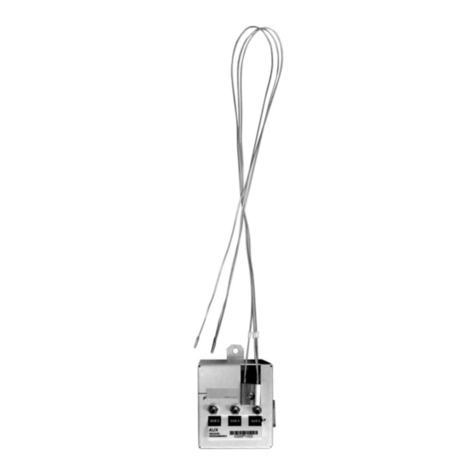
b) Install temperature sensor:
do not immerse sensor in liquids nor install it within stream of flue gases
install the CH system inlet temperature sensor at the boiler point specially designed for
that purpose or on an unshielded boiler outlet pipe (as close to the boiler as possible
using hose clips tighten the sensor to the pipe.
c) Hook up pump power supply cable:
connect yellow (or yellow-green PE wire with the terminal
connect blue wire with the N terminal
connect brown wire with the L terminal.
d) Verify the connections:
check up all cable connections and tighten terminal box lids.
e) Hook up the controller:
make sure controller cables are protected against incidental cut off
plug the controller power supply cable into a 230V/50Hz mains socket equipped with a
grounding pin.
The controller must not be installed in a place where the ambient
temperature may exceed 40ºC.
5. TURNING THE CONTROLLER ON
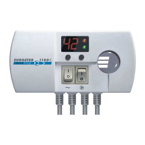
Turn the controller mains switch (1 in section 3 into the “I” position.
Green LED (6 in section 3 goes ON
In case of the E11C controller model its ANTY STOP function turns the pump on for
about 30 seconds (red LED goes ON
Using the knob set the desired temperature.
6. AUTOMATIC OPERATION
The EUROSTER E11/11C controller engages/disengages CH system circulation pump
depending on sensor temperature in relation to the knob-preset temperature set point. The
pump is turned ON as soon as sensor temperature exceeds the set point, and is turned OFF as
soon as it drops below the set point.
7. MANUAL OPERATION
Manual pump switch of the EUROSTER E11/11C controller may be useful e.g. to help de-
aerate the system or in case of a failure of the temperature sensor.
1. Turn the continuous operation switch (8 in section 3 into the “I” position (red LED goes ON .
2. The pump will be engaged regardless of the actual sensor temperature in relation to the
controller set point.
8. TROUBLESHOOTING
a) Device is dead (green LED does not go ON)
Burnt mains fuse or ROM failure. Replace the fuse or have the controller serviced.
