EUROSTER 1100E – USER MANUAL 2
•connect the brown wire to terminal (L)
d. check-u of connections:
•make sure the connections have been made as indicated and secure the cover of the
pump motor terminal box
e. connection of the controller:
•upon securing the cables against accidental pullout, connect the ower su ly cable
to a 230V/50Hz grounding socket.
IMPORTANT: At the mounting location of the controller ambient temperature should not
exceed 40ºC.
2. OPERATION
After switching on the controller allow ca. 30 sec. for the controller to become fully
o erational
a. start u :
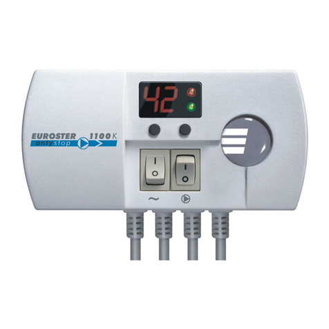
•set the left-hand toggle switch (~) to position I,
•upon energising all the segments of the display light up for 2 seconds,
•the current temperature, as measured by the sensor is displayed and the controller
operates according to the factory settings (temperature limit of 50°C).
b. descri tion of dis lay functions
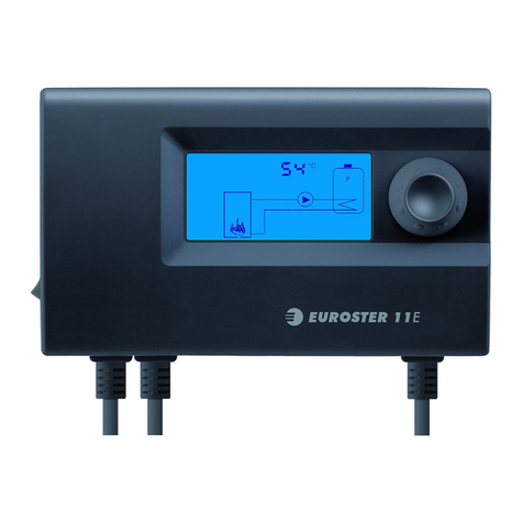
•display continuously on – current temperature, as measured by the sensor,
•blinking display – temperature setpoint,
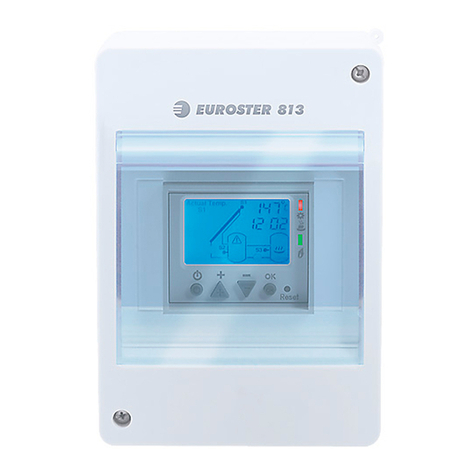
•red LED on – controller is switched to DHW mode
•green LED on – controller is switched to heating mode
•dot appears after the second figure – pump in operation
c. selection of the o erating mode
•for switching between DHW and heating modes use the left-hand toggle switch under
the display
d. setting the tem erature
•press the right-hand switch under the display – the figures will start blinking and the
current setpoint is displayed,
•use the right-hand and left-hand switches to increase decrease the displayed
temperature setpoint, as appropriate,
•after ca. 4 sec. the display will stop blinking indicating that the preset temperature has
been stored. The display will return to displaying the current temperature, as measured
by the sensor.
e. automatic o eration mode
•set the right-hand switch () to 0,
•the circulating pump is switched on off depending on the temperature setpoint,
•in the heating mode the controller will switch on the pump when the temperature
measured on the sensor has exceeded the setpoint by 2°C and switch it off when the
temperature has dropped by 3°C below the setpoint [5°C hysteresis],
•in the DHW mode the controller will switch on the pump when the temperature
measured on the sensor has dropped by 2°C below the setpoint and switch it off when
the temperature has exceeded the setpoint by 1°C [3°C hysteresis].
IMPORTANT!
In a hydronic heating system supplied by a coal-fired boiler the thermostatic controller
will switch off the pump upon flame failure. Pumping of water upon flame failure should be
