EUROSTER UNI4 User manual

EUROSTER UNI4 –USER MANUAL 1
EUROSTER UNI4
Weather-based heating system controller
MANUFACTURER: P.H.P.U. AS, Chumiętki 4, 63-840 Krobia, Poland
In order to take full advantage of the controller capabilities and ensure proper operation of the
central heating system, please read this user manual carefully.
Manual version: 01.02.2021
1. APPLICATION
UNI4 is a universal controller designed to control a heating system equipped with:
◼Two independent CH zones with mixing valves (e.g. for floor heating, radiator heating)
◼DHW circuit
◼DHW circulation circuit (time-based control)
◼Heating source control
◼Feeding the buffer which supplies other zones
◼Ability to control cooling or heating zones with a switch-over between heating and
cooling by an external contact.
Heating system diagram

EUROSTER UNI4 –USER MANUAL 2
S1 –Feeding temperature sensor 1
(buffer –top)
S2 –Feeding temperature sensor 2
S3 –Buffer temperature sensor - bottom
S4 –CH1 zone temperature sensor
S5 –CH2 zone temperature sensor
S6 –DHW temperature sensor
S7 –Outdoor temperature sensor
R1 –CH1 zone room thermostat
R2 –CH2 zone room thermostat
1. Feeding source No. 1
2. Feeding source No. 2
3. Buffer tank
PB –Buffer pump (feeding no. 2)
P1 –CH1 zone pump
P2 –CH2 zone pump
P3 –DHW tank feeding pump
P4 –DHW circulation pump
M1 –230 V 3-point actuator of the mixing valve
in CH1 zone
M1 –230 V 3-point actuator of the mixing valve
in CH2 zone
Heating/cooling system diagram
In the case of active cooling, the function of the DHW tank and feeding source
temperature control is unavailable!
S4 –CH1 zone temperature sensor
S5 –CH2 zone temperature sensor
R1 –CH1 zone room thermostat
R2 –CH2 zone room thermostat
P1 –CH1 zone pump
P2 –CH2 zone pump
P4 –DHW circulation pump
M1 –230 V 3-point actuator of the mixing
valve in CH1 zone
M1 –230 V 3-point actuator of the mixing
valve in CH2 zone
1. Controller output for switching on the
heating or cooling device.
2. FUNCTIONS
2.1. CH zones
◼Control of the CH pump and the 3-point actuator of the mixing valve
◼Independent setting of temperature and weather curve for each zone
◼Independent control of each zone with a room thermostat and weekly schedule
◼Possibility to switch off any zone
◼Manual switching between summer and winter season
◼Selection of a zone operating mode if heating is not needed: by turning the pump on or
off or by decreasing the temperature with a mixing valve with the pump being switched
on permanently or by switching on the zone temporarily
◼Cooperation with the floor heating distributors

EUROSTER UNI4 –USER MANUAL 3
◼Switching off the heating automatically in case of outdoor temperature increase.
2.2. DHW circuit –filling the DHW tank
◼Controlling the weekly schedule
◼DHW priority
◼Temporary limitation of DHW priority
◼Disinfection of DHW circuits - with the schedule of periodic disinfection.
2.3. DHW circulation circuit
◼Controlling the weekly schedule
◼Time-base control (without temperature control)
2.4. Feeding
◼Automatic identification of the preset temperature and control of the heating source
◼Weekly schedule of the heating source operation
◼Cooperation with the heat buffer
◼Possible operation with two heating sources
◼Possible operation without feeding temperature sensor (cooperation with heat
distribution units).
2.5. Utility functions
◼Control of a gas-fired boiler or other heating devices with a voltage-free output (NO/NC
relay contacts)
◼Alarm output (230 V 50 Hz output)
◼Event log (the controller stores 15 last alarms or irregular situations)
◼Supported languages: Polish, English, German
◼Possibility to test each output
◼Overheating protection
◼Cooperation with systems with high feeding temperature (up to 110°C) – on customer’s
request
◼Frost protection
◼Anti-Stop algorithm –protection of pumps and valves against seizure.
◼Caution! The controller does not communicate with UNI2 and UNI3 controllers.
3. USER INTERFACE
3.1. Main screen
The following information is shown on the main screen:
◼Zone temperatures: current and preset (calculated with a weather-based algorithm)
◼Active devices (pump, mixer, boiler)
◼Controller status (anti-stop, disinfection, heating season: WINTER/SUMMER and others)
◼Time and date.
An example screen with a description is shown below:
Additional heating source on (feeding no.2, without the buffer)

EUROSTER UNI4 –USER MANUAL 4
Additional heating source on (feeding no.2, with the buffer)
The symbols shown in the controller have the following meaning:
Pump operation
Mixer operation
No icon –thermostat operation off; flashing icon –thermostat operation on; active
symbol - heating switched on by a room thermostat
Anti-Stop algorithm active
Thermal cleansing of DHW
Main heating source active (feeding no. 1) –boiler relay output (NO-COM) shorted
Activated DHW priority function
Additional heating source active (feeding no. 2) –voltage at the buffer pump output
AF
Frost protection switched on
3.2. Multifunction knob
The controller is operated with a multifunction knob. In addition to a rotary face used to
change the set value, it contains 4 buttons used for navigation (selecting between menu items:
up, down, next, previous) and a confirmation button located in the center of the knob, which
also clears the display of alarm warnings.
CAUTION! When changing a setting, the new value is only stored after being
confirmed with the center or right button.
3.3. LED
A light-emitting diode is located on the left-hand side of the display. The colors have the
following meaning:
◼Green: Operation, no errors
◼Red: An error has occurred
◼Blue: Menu active
◼Yellow: Output testing mode
3.4. Reset and restoring factory settings
To restore factory settings, press the Reset button and hold it for at least 5 s; the factory
settings window will be displayed.
The options are:
◼Reset –YES/NO
◼Language selection
◼Cooling –YES/NO
◼Store/EXIT
Select “Reset”, switch to YES, and confirm by selecting “Store/EXIT”.
CAUTION! Restoring factory settings may lead to improper operation of the system
and in extreme cases, it may lead to a failure or damage to the system.

EUROSTER UNI4 –USER MANUAL 5
3.5. List screens
The controller settings are arranged hierarchically, according to the zone -> parameters order.
Only the basic settings are available for the user. Advanced options are included in “Settings”
and are protected with an access code.
3.6. Setting screens
Adjustable parameters with comments are listed below.
3.6.1. User settings
CH1 zone
◼The preset temperature of the zone
It is the zone temperature maintained with the use of the mixer. When operating with
the weather sensor, there are three settings (based on which the heating curve is
established). When operating without the weather sensor, one setting is available.
◼Schedule
With the use of schedule a zone may be switched off for the selected time on selected
days of the week.
CH2 zone
◼Parameters identical to the CH1 zone
DHW circuit
◼DHW temperature
It is the tank temperature to be maintained by the controller.
◼DHW schedule
With the use of schedule, we may preset time to feed the DHW tank on selected days of
the week.
DHW circulation circuit
◼schedule
With the use of schedule, we may preset the time of DHW circulation circuit operation
on selected days of the week.
Heating season
Switching to the “SUMMER” season results in switching off the CH 1 and CH 2 zones, DHW
circuits operate normally.
Switching to the “WINTER” season results in switching on the CH zones and DHW circuits.
Date and time
In this window, a user may enter the current date and time. Please remember that the
operation of the schedules, control algorithms, and events log is only correct with the correct
settings.
Output testing
Testing all outputs by switching them on and off. Provides the possibility to check the correct
operation of all devices connected to the controller. After 2 minutes the controller exits the
testing mode and switches to automatic operation.
Settings
Entering advanced settings (installer settings).
3.6.2. Technician’s settings
The technician’s settings are available after entering the access code. The default code is “1,
2, 3”.
CAUTION! It is recommended to restore factory settings before configuring a new
controller.
Settings for CH 1 zone (identical ones for CH 2 zone)
◼Switching the zone on/off

EUROSTER UNI4 –USER MANUAL 6
Switching off the unused zone.
◼Mixer
◼Mixer dynamics
Determines the time of mixer response to changes in the zone temperature. An
excessive value may cause frequent cycling of the mixer, whereas the insufficient
value may cause slowness in achieving the preset temperature.
◼Mixer hysteresis
If the measured temperature of a zone differs from the preset one by half of the
value of preset hysteresis, then the mixer position is not corrected.
◼Alarm temperature
CAUTION! Alarm temperatures for all zones should be selected carefully.
Incorrect setting of temperature level may cause improper operation or major
failure of the system components.
The alarm temperature should be preset as the maximum safe temperature for a
particular zone.
◼Room thermostat
In this item, a user may switch off the inputs of room thermostats. In such a case the
central heating will be switched on regardless of the requests of thermostats.
◼Weather compensator
Weather compensation provides a possibility to achieve thermal comfort regardless of
external temperature. The only requirement is to connect an outdoor temperature
sensor.
After switching the weather compensation on, temperatures of the CH zones for three
outdoor temperatures should be set. Based on those the controller calculates the
currently required zone temperatures every 10 minutes.
CAUTION! Temperatures must meet the condition of T10ºC ≤ T0ºC ≤ T-20ºC
otherwise, the control will not work properly.
◼Maintenance operation –if a given zone does not require heating (the schedule is
not selected or room thermostat contact is open) the controller will respond in the
following way:
◼stop –the pump will be switched off and the mixer closed,
◼time-based –the zone will be switched on for a preset time with the preset idle
time, the zone temperature will be decreased by the value of the "Reduction”
setting,
◼continuous –the pump does not switch off, the mixer reduces the zone
temperature by the value of the "Reduction” setting.
Settings for DHW circuit
◼Switching the circuit on/off
In this item, a user may switch off the DHW circuit if not used.
◼Hysteresis
It is a difference between the temperature at which the tank feeding pump is switched
off and on.

EUROSTER UNI4 –USER MANUAL 7
◼DHW allowance
The “DHW allowance” parameter determines the value by which the temperature of the
heating source must exceed the temperature of the tank. Setting a higher temperature
ensures adequate heating capacity and compensates for the heat loss due to the
imperfect insulation of pipes connecting the boiler to the tank.
If the temperature of the heating source is not sufficiently high, then the DHW tank
feeding pump is not switched on.
◼DHW priority
Switching on the DHW priority means that the controller switches off the CH zones for
the time when DHW is heated, this way the temperature preset for the tank is achieved
as fast as possible.
◼Priority operation time, priority break time
The time limit for the DHW priority operation prevents excessive cooling of rooms when
the tank may not be properly heated in a reasonable time.
To use this function, the priority break time must be set to a value other than zero.
The DHW tank is being heated for the period preset by the “Priority operation time”
parameter ( icon displayed), then the DHW priority is switched off for the “Priority
break time” ( icon flashing in the display). Subsequently, the DHW priority is
switched on again.
◼Disinfection
Switch on/off
This item enables a user to switch on periodic disinfection according to the schedule.
Schedule
Selecting adequate days results in switching on the disinfection at 0.00.
The proper cleansing consists in heating the DHW tank to the temperature of 70°C and
flushing the pipes with hot water.
The disinfection ( icon active in the display) may last for 2 hours maximum. If the
preset temperature of the tank is reached within 2 hours, the disinfection is successful.
If the tank fails to reach the temperature of 70°C in 2 hours, the disinfection is stopped
and the message informing of unsuccessful disinfection is displayed.
Activate
Activates disinfection manually on a one-off basis.
◼Alarm temperature
If the tank is fed by another, additional heating source and the tank temperature
exceeds the alarm temperature, then the controller switches on the DHW pump which
cools down the tank. It is indicated with an error of DHW overheating. The pump is
switched on only if the feeding temperature is lower than the preset alarm temperature
of the DHW tank.
CAUTION! When the alarm is activated please take special precautions to avoid
getting burned by the domestic hot water.
Settings for DHW circulation circuit
◼Switching the circuit on/off
This item enables a user to switch off the circulation circuit when not used.
◼Circulation operating time setting range from 1 to 99 minutes
◼Circulation idle time setting range from 1 to 99 minutes
Feeding no. 1
◼S1 sensor on/off
Switching the feeding temperature sensor (main heating source) on or off.
If the sensor is off, then the CH 1, CH 2 zones, and DHW circuit operate according to
their operating algorithms and disregard the feeding temperature.
If the S1 sensor is on, the following parameters are available.

EUROSTER UNI4 –USER MANUAL 8
◼Boiler relay output (feeding no. 1) determines the way of boiler relay operation:
◼AUTO –the temperature preset for the feeding temperature sensor will be
established automatically depending on the demand for heat in individual zones.
The preset temperature will be determined based on the formula: the highest
temperature of the CH 1, CH 2 zone, DHW circuit + the “Allowance” parameter
◼TEMP –maintains constant preset temperature on the S1 feeding sensor
When the temperature on the feeding sensor drops by the value of the hysteresis,
then the boiler relay is switched on.
◼Schedule
Hourly schedule of boiler operation. Provides the possibility to select the time of heating
source operation. The function is handy if, e.g. the electric heating operates in the 2nd
charging rate.
◼Feeding temperature (the parameter is available with the following settings: Boiler
relay output –TEMP) –S1 sensor temperature setting, above which the boiler relay
output will be switched off.
◼Hysteresis –the parameter determining the number of degrees by which the feeding
temperature must drop below the preset temperature (or calculated in AUTO mode),
for the boiler relay to be activated.
◼Alarm temperature
When the feeding alarm temperature is exceeded, the alarm algorithm is activated in
an attempt to cool down the boiler.
CAUTION! The alarm algorithm heats zones to temperatures approximate to
alarm temperatures. It is important to ensure a safe level of alarm
temperature for each zone.
◼Pump starting temperature
Above this temperature, the pumps of CH 1, CH 2 zones, and DHW circuit are activated.
◼Allowance (the parameter is available with the following settings: Boiler relay output –
AUTO)
The parameter determines by how much the feeding temperature must exceed the
temperature calculated by the controller for zones.
Feeding no. 2
◼S2 sensor on/off
Provides the possibility to switch on the support of buffer pump –the additional heating
source.
◼Switch-on temp.
Exceeding the switch-on temperature results in switching on the buffer pump and
switching off the feeding relay (boiler relay output). and
◼Hysteresis –the parameter determining by how many degrees must the S2 sensor
temperature drop below the switch-on temperature, so that the buffer pump relay is
switched on.
◼Feeding alarm temperature
When the feeding alarm temperature is exceeded, the alarm algorithm is activated in
an attempt to cool down the boiler.
◼Buffer on/off
When buffer operation is active, two preset temperatures for buffer heating are
available:
◼Top temperature (S1 sensor) –it is a preset temperature, up to which the top
part of the buffer will be heated
◼Bottom temperature (S3 sensor) –it is a preset temperature, up to which the
bottom part of the buffer will be heated
The buffer is heated by the buffer pump. The temperature at the S2 sensor must
exceed the temperature of the buffer by 3°C so that the buffer pump is switched on.
The preset top and bottom temperatures are not displayed.

EUROSTER UNI4 –USER MANUAL 9
Correction of sensors
Correction of temperature sensors allows to correct temperature reading errors, such as the
ones resulting from improper contact between the sensor and the pipe.
Automatic operation
The function enabling automatic switch-off of the CH 1 and CH 2 zones if the temperature of
the S7 sensor (outdoor sensor) exceeds the preset value of the "Switch-off temperature".
The heating will be restarted if the external temperature drops below the preset value of
"Switch-on temperature".
The automatic operation mode is available when the outdoor temperature sensor is connected
and WINTER season selected.
Events
The device records hazardous events. The display shows subsequently: Event number (since
the installation), date, time, and comments, e.g.: 11. 19-09 14:16:38 DHW overheating
4. INSTALLATION
4.1. Connection
◼Prior to the commencement of any installation works read this manual carefully!
Incorrect installation and handling of the controller result in loss of manufacturer's
warranty.
◼Prior to mounting or dismantling the controller make sure that it is de-energized.
Connection and disconnection of temperature sensors should also be performed when
the device is de-energized.
◼Voltages hazardous to life are present on the controller and its connections, therefore
only qualified and authorized technicians may be entrusted with the installation of the
controller.
◼Install the controller in the circuit with proper electrical protections, in accordance with
current regulations.
◼The performed electric connections and cables used shall be adequate to the applied
loads and must conform to all requirements.
◼Do not install the controller in rooms of increased humidity, protect it against water and
other liquids.
◼The controller is designed to be mounted on a 35 mm DIN rail in a protective cabinet.
◼Do not install any controller showing signs of mechanical damage.
◼The controller is not a safety component. Additional protection devices must be used in
systems prone to the risk of damage due to the failure of control systems.
CAUTION! Euroster Uni4 controller and a heat emitting device are connected to the
“BOILER RELAY” output and must be powered from the same phase of the power
system.
CAUTION! When connecting power cables, pay particular attention to the correct
connection of PE conductors.
The temperature sensors are not suitable to be immersed in liquids.
The controller interacts only with actuators equipped with limit switches.
The controller must be installed in a place where ambient temperature does not exceed 40°C.
All necessary cables must be laid prior to mounting the device.
Screw the electric cables to the connection blocks according to the description and drawing.
Make sure to keep the proper designation of the cables. Screw the neutral conductors to N
terminals, phase conductors to L terminals, and grounding conductors to PE terminals. Connect
the device using a cable with a minimum diameter of 0.75mm².
The controller is equipped with seven temperature sensors. It is not necessary to connect
sensors for the switched-off zones/functions.
The controller sensors may be connected in any way, with no need to keep cable polarity. At
installation avoid leading the sensors parallel to live cables. Moreover, make sure to provide
the proper contact with measured surfaces.
The outdoor temperature sensor should be installed in a shaded place, away from windows and
doors, at a height of approximately 2 m above ground.

EUROSTER UNI4 –USER MANUAL 10
A room thermostat control may be switched on or off for each central heating zone. It is only
allowed to use thermostats with a voltage-free normally open (NO) contact. It is
recommended to use Euroster devices.
The connection diagram is shown below.

EUROSTER UNI4 –USER MANUAL 11
Connection diagram for the cooling mode.

EUROSTER UNI4 –USER MANUAL 12
5. CONTROLLER OPERATION
CAUTION! Once the controller is switched on the Anti-Stop algorithm is activated
(pump and mixer outputs are switched on for 30 seconds). The Anti-Stop mode is
repeated every two weeks, regardless of the heating season.
5.1. Feeding temperature
The UNI4 controller uses the feeding relay 1 (boiler relay output) to control the operation of
the main heating source in order to achieve the required temperature at the S1 feeding
sensor.
There are 2 heating source operation modes available in the "Settings" –"Feeding no.1"–
"Boiler relay output" menu:
◼AUTO –the preset temperature is established automatically according to the demand
for heat from CH1, and CH2 zones, and DHW circuit and increased by the value of the
"Allowance” setting. Additionally, the time of heating source operation may be selected.
◼TEMP –feeding temperature is maintained at a constant level. Additionally, the time of
heating source operation may be selected.
5.2. Heating zones
Heating in the selected zone is active if:
◼a given CH zone is active,
◼the heating season (WINTER) is switched on,
◼the current time is selected in the schedule of the zone,
◼the room thermostat demands heating or operation with room thermostat is switched
off,
◼DHW tank is heated or DHW priority is switched off,
◼feeding temperature exceeds the required one.
CH circulation pump is switched on if heating is active and the mixer is not closed. However, if
“maintenance operation” – “continuous operation” was activated, the pump operates without
interruption, and the room temperature is controlled by opening or closing the mixer, taking
into account the “Temperature reduction” parameter.
CAUTION!
The temperature preset for a given CH zone is not displayed if:
◼The CH zone is switched off,
◼The room thermostat achieved a target temperature and switched the zone off,
◼There is an idle time set up in an operation schedule of the selected zone,
◼DHW priority function is active.
5.3. DHW circuit
DHW tank heating is on if:
◼DHW circuit is switched on,
◼The current time is selected in the DHW schedule.
◼The temperature of the tank is too low,
◼The feeding temperature is adequate (higher than the DHW).
5.3.1. Disinfection of the DHW system
Maintaining low DHW temperature (at the level of 40ºC) facilitates the development of
bacterial flora in the system. In order to perform disinfection, take the following steps:
◼Switch on disinfection in the DHW menu,
◼Ensure the feeding temperature is not lower than shown by the controller –heating of
the tank and circulation circuit starts,
◼Open the taps and flush the system with hot water (take necessary precautions against
possible burning).
5.4. DHW circulation
The circulation circuit is active, when:
◼The circulation circuit is switched on,
◼The current time is selected in the circulation schedule
◼The system is being disinfected.

EUROSTER UNI4 –USER MANUAL 13
The circulation pump operates according to the preset operating and idle times. Operation
based on the temperature sensor readout is not possible.
5.5. Alarm output
The alarm output is used to connect an additional, external alarm indicator.
In case of sensor damage, zone overheating, or other errors, voltage is supplied to the alarm
output.
CAUTION! The alarm indicator must be adjusted to the network voltage of 230 V.
Simultaneously, appropriate information with the time of error will be displayed.
5.6. Boiler Relay Output (Feeding no.1) –voltage-free
Boiler Relay Output is used for switching on the main heating source.
The feeding no. 1 sensor (S1) control may be switched off, then the controller does not affect
feeding temperature. The zones will operate according to their operating algorithms.
In such a case the temperatures of S1, S2, S3 sensors are not shown and are not required to
be connected to the controller.
CAUTION! When the S1 sensor is deactivated, operating the additional feeding
source (feeding no. 2) is unavailable, the control of buffer feeding is also switched
off.
In the operating mode with feeding sensor S1 switched off, the boiler relay output status
depends neither on the feeding temperature nor on the CH zone temperatures. This output is
switched on if heating of any zone is required. It is switched off when a gap in heating is
preset in the schedules or during operation with room thermostat (when thermostat output is
disconnected after reaching the preset temperature in rooms).
5.7. Buffer Pump Output (Feeding no.2) –voltage type
This output is used to control the buffer pump –the pump of additional heating source.
If at the S2 sensor the temperature exceeds the preset “Switch-on temperature” parameter,
then the boiler relay is switched off and the buffer pump is activated.
Operation with the heat buffer
Heating source No. 2 is used for feeding the buffer. The temperature of this heating source
(sensor no. 2) must be higher than the preset “Switch-on temperature” and by 3°C higher
than the bottom and top temperature of the buffer.
The buffer is fed until both preset temperatures, the top and the bottom, are achieved.
If the temperature at the S2 sensor drops and the buffer pump is switched off, then the main
heating source is switched on (boiler relay output), to continue feeding the buffer until the
preset temperatures –the top and the bottom one –will have been reached.
5.8. Cooling
UNI4 controller handles control of the cooling system in the summer season, and the
heating system in the winter season. In the cooling mode the control of DHW, and
feeding source no. 1 and no.2 is not active, and the weather-based control does not
work.
Switching on the cooling system: press and hold the RESET button until the settings window is
displayed. There is the “Cooling”item available in line 3, select YES and confirm.
From this moment on the switch-over between cooling/heating mode is executed by shorting
S3 input:
◼Cooling –open
◼Heating –shorted
Separate temperature settings ad separate operation schedules are provided for
heating and cooling mode.

EUROSTER UNI4 –USER MANUAL 14
6. POSSIBLE ERRORS IN THE CONTROLLER OPERATION
6.1. A selected zone is not heating –closed valve or inactive pump
Check:
◼Whether the heating season is switched on,
◼Whether the correct date (day of the week) and time is set,
◼Whether heating is active in the schedule for the current day of the week and time,
◼In the system with a weather compensator –whether the outdoor temperature reading
is correct and whether the temperatures are set correctly,
◼Whether DHW priority heating is switched off,
◼In the system without room thermostat –whether it is switched off in the controller,
◼In the system with a room thermostat –whether it is switched on and correctly
connected to the controller,
◼Whether the mixer is not connected inversely and whether it is not jammed,
6.2. A selected zone is subject to overheating
Check:
◼Whether the valve is not blocked,
◼Whether the mixer actuator is operating,
◼Whether the actuator cables are connected properly,
◼The value of mixer dynamics.
7. DIMENSIONS
8. TECHNICAL DATA
Supply: 230 V 50 Hz
Maximum power consumption: 4 W
Maximum output load: 100 W (each output)
Temperature adjustment range:
◼CH zones from 5°C to 90°C
◼DHW circuit from 5°C to 90°C
Temperature measurement range: -30°C...120°C
Temperature control and reading accuracy: 1°C
Operation temperature range: 0...40°C
Storage temperature range: 0...55°C
Ingress protection rating: IP20, Protection Class II
Color: gray, RAL7035
Mounting method: 35mm DIN rail-mounted, inside electrical cabinets
Alarm output: 230 V 50 Hz
Boiler output: voltage-free type, NO/NC, maximum load: 4A 230V 50Hz
Pump power outputs: 230 V 50 Hz
Power outputs of mixer actuators: 230 V 50 Hz
Controller weight: 545 g

EUROSTER UNI4 –USER MANUAL 15
9. KIT CONTENTS
UNI4 CONTROLLER
Outdoor temperature sensor (5 m) –1 piece
S1, S3 Feeding temperature sensor (1.5 m) –2 pieces
Tank temperature sensor (2.5 m) –1 piece
S2 feeding temperature sensor (2.5 m) –1 piece
S4, S5 CH zone temperature sensors (1.5 m) –2 pieces
Sensor hose clips (6 pieces)
Power cable (1.5m) –1 piece
Screw anchors –4 pieces
User Manual with Warranty Certificate
10. SIMPLIFIED DECLARATION OF CONFORMITY
P.H.P.U. AS AGNIESZKA SZYMAŃSKA-KACZYŃSKA hereby represents that the type of Euroster
UNI4 equipment conforms to the following directives: 2014/35/EU (LVD), 2014/30/EU (EMC),
2011/65/EU (RoHS). The complete text of the Declaration of EU conformity is available at the
following Internet address: www.euroster.pl.
11. ELECTRONIC WASTE MANAGEMENT INFORMATION
This product is designed and manufactured from high-quality materials and
components suitable for reuse.
The crossed-out wheelie bin symbol located at the product means that the product
is subject to selective collection in accordance with the provisions of the Directive
2012/19/EU of the European Parliament and the Council.
The product contains an internal battery subject to the selective collection in accordance with
the provisions of the Directive 2006/66/EC of the European Parliament and the Council.
Such marking informs that the electrical and electronic equipment and batteries may not be
disposed of together with other household waste after their service life. The user is obliged to
take the used devices and batteries to a point of collection of waste electrical and electronic
equipment and batteries. The entities collecting such equipment, including the collection
points, shops, and municipal entities, set up an appropriate system enabling the handover of
such equipment and batteries. The proper disposal of waste equipment and batteries
contributes to the prevention of consequences hazardous to the health of persons and nature,
resulting from the possible presence of hazardous components in the equipment and batteries
and inaccurate storage and processing of such equipment and batteries. The guidelines
regarding the disposal of the batteries are included in the user manual.
A household plays an important role in contributing to the reuse and recovery of waste
equipment including recycling. The attitudes influencing the protection of the common good of
a clean environment are shaped at this level. Households are also one of the larger users of
small equipment and its rational management at this stage impacts the recovery of
recyclables. Inaccurate disposal of this product may be penalized in accordance with national
legislation.

EUROSTER UNI4 –USER MANUAL 16
WARRANTY CERTIFICATE
EUROSTER UNI4 CONTROLLER
Warranty terms:
1. The warranty is valid for 24 months from the device sale date.
2. Rights under the warranty are exercised within the territory of the Republic of Poland.
3. The claimed thermostat together with this warranty certificate must be supplied to the
seller or directly to the manufacturer by postal services of Poczta Polska.
4. Warranty claims shall be processed within 14 business days upon the day when the
manufacturer received the claimed device.
5. The device may be repaired exclusively by the manufacturer or by a party clearly
authorized by the manufacturer.
6. Warranty becomes void in case of any mechanical damage, incorrect operation, and
repairs made by unauthorized persons.
7. This consumer warranty does not exclude, restrict nor suspend any right of the buyer if
the product does not meet any of the sale contract terms.
...................................................................................................................................
Sale date
Serial number / date of
manufacture
Stamp
and signature
Service:
Phone No. (+48) 65-
57-12-012
The business entity that issued this Warranty Certificate is:
P.H.P.U. AS Agnieszka Szymańska-Kaczyńska, Chumiętki 4, 63-840 Krobia, Poland
Table of contents
Other EUROSTER Controllers manuals
EUROSTER
EUROSTER 11W User manual
EUROSTER
EUROSTER 12M User manual

EUROSTER
EUROSTER 10M User manual
EUROSTER
EUROSTER R1100WB User manual
EUROSTER
EUROSTER 11Z User manual

EUROSTER
EUROSTER C6RX User manual
EUROSTER
EUROSTER 10PC User manual

EUROSTER
EUROSTER 11 User manual

EUROSTER
EUROSTER 1100E User manual
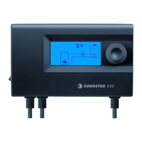
EUROSTER
EUROSTER 11E User manual
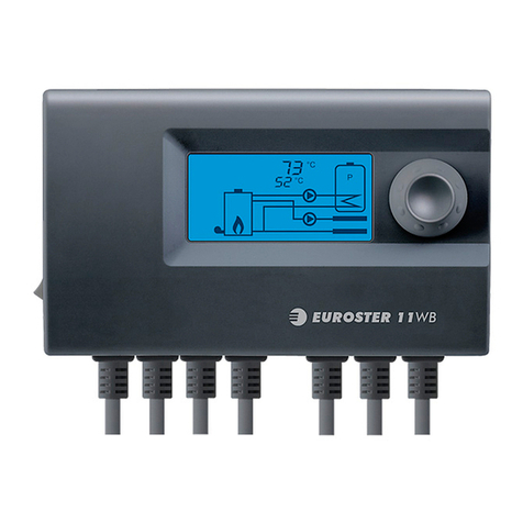
EUROSTER
EUROSTER 11WB User manual

EUROSTER
EUROSTER 11E User manual

EUROSTER
EUROSTER 11W User manual
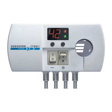
EUROSTER
EUROSTER 1100K User manual
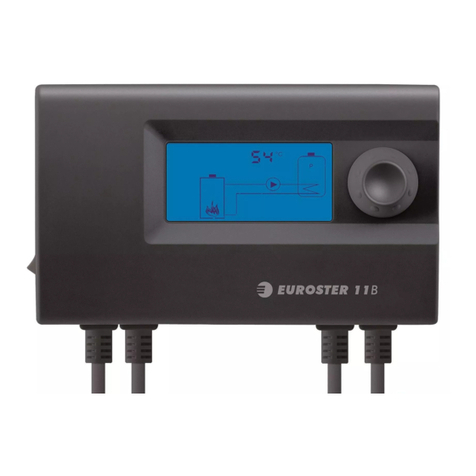
EUROSTER
EUROSTER 11B User manual
EUROSTER
EUROSTER FH1 User manual
EUROSTER
EUROSTER 11M User manual

EUROSTER
EUROSTER 11K User manual
EUROSTER
EUROSTER 813 User manual

EUROSTER
EUROSTER 11Z User manual

