manuals.online logo
Brands
  1. Home
  2. •
  3. Brands
  4. •
  5. Evco
  6. •
  7. Controllers
  8. •
  9. Evco EV8318 User manual

Evco EV8318 User manual

EVCOS.p.A.|EV8318|Instructionsheetver.2.0|Code1048318E203|Page1of4|PT47/18
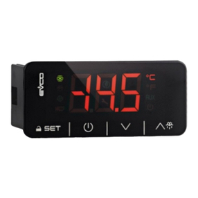
EV8318 Controller for bread and pizza deck ovens
I ENGLISH
- power supply 115... 230 VAC or 24 VAC (according to the model)
- built-in clock
- chamber probe or top and floor probes (J/K or Pt 100 2-wire)
- multi-purpose input
- steam generator relay, 16 A res. @ 250 VAC
- alarm buzzer
- TTL MODBUS slave port for programming key or for TTL/RS-485 (BMS) serial interface
- USB port (set up recipe book)
- on-off/PI control
- independent regulation of the power or the top and floor temperature.
Models available
Purchasing
code
Power supply
Type of
analogue inputs
Number of
digital outputs
Type of digital
outputs for
top and floor
EV8318J9
115... 230 VAC
for J/K thermo-
couples or
Pt 100 2-wire
probes
8
electro-
mechanical
relay
EV8318J4
24 VAC
for Pt 100 2-wire
probes and
J/K thermocou-
ples
8
electro-
mechanical
relay
1 MEASUREMENTS AND INSTALLATION
Measurements in mm (inches). To be fitted to a panel, screwed-in brackets provided.
INSTALLATION PRECAUTIONS
- the thickness of the panel must be between 0.8 and 5.0 mm (1/32 and 1/16 in)
- the maximum clamping torque applicable to the screwed-in brackets is 10 cNm
- ensure that the working conditions are within the limits stated in the TECHNICAL
SPECIFICATIONS section
- do not install the device close to heat sources, equipment with a strong magnetic field,
in places subject to direct sunlight, rain, damp, excessive dust, mechanical vibrations
or shocks
- in compliance with safety regulations, the device must be installed properly to ensure
adequate protection from contact with electrical parts. All protective parts must be
fixed in such a way as to need the aid of a tool to remove them.
2 ELECTRICAL CONNECTION
N.B.
- use cables of an adequate section for the current running through them
- ensure that the thermocouple is properly insulated from contact with metal parts or
use already insulated thermocouples
- if necessary, extend the thermocouple cables using compensating cables
- where they are two multi-purpose inputs, multi-purpose input 1 has priority over
multi-purpose input 2
- the TTL MODBUS port can be used as an alternative to the USB port and vice versa
- to reduce any electromagnetic interference locate the power cables as far away as
possible from the signal cables.
PRECAUTIONS FOR ELECTRICAL CONNECTION
- if using an electrical or pneumatic screwdriver, adjust the tightening torque
- if the device is moved from a cold to a warm place, humidity may cause condensation
to form inside. Wait for about an hour before switching on the power
- make sure that the supply voltage, electrical frequency and power are within the set
limits. See the section TECHNICAL SPECIFICATIONS
- disconnect the power supply before carrying out any type of maintenance
- do not use the device as a safety device
- for repairs and for further information, contact the EVCO sales network.
3 FIRST-TIME USE
1. Carry out the installation following the instructions given in the section MEASUREMENTS
AND INSTALLATION.
2. Power up the device as set out in the section ELECTRICAL CONNECTION: an internal
test will start up.
The test normally takes a few seconds; when it is finished the display will switch off.
3. Configure the device as shown in the section Setting configuration parameters.
Recommended configuration parameters for first-time use:
PAR. DEF. PARAMETER MIN... MAX.
P0
0
type of probe
0 = J 1 = K
2 = Pt 100 2-wire
P1 0 unit of measurement 0 = °C 1 = °F
P2
0
operating logic
0 = independent regulation of the
top and floor power
1 = independent regulation of the
top and floor temperature
r3
130
chamber setpoint
r1... r2
if P2 = 1, top setpoint
r6 130 floor setpoint r4... r5
Then check that the remaining settings are appropriate; see the section CONFIGURA-
TION PARAMETERS.
4. Disconnect the device from the mains.
5. Make the electrical connection as shown in the section ELECTRICAL CONNECTION with-
out powering up the device.
6. When connecting to an RS-485 network, connect the EVIF22TSX interface.
7. Power up the device.
4 USER INTERFACE AND MAIN FUNCTIONS
4.1 Switching the device on/off
To switch the device on:
1. Touch the ON/STAND-BY key.
To switch the device off:
1. Touch the ON/STAND-BY key for 3 s.
If the device is on and the operating logic has independent regulation of the top and floor
power (P2 = 0, default), the display will show:
If the chamber setpoint has been reached, the status of the device will show “READY", if not, it
will show "PRE-HEATING".
If the device is on and the operating logic has independent regulation of the top and floor tem-
perature (P2 = 1), the display will show:
If the top and floor setpoints have been reached, the status of the device will show "READY", if
not, it will show "PRE-HEATING".
If the device is switched off, the display will show the time. If the weekly programmed switch-
on function is activated, the display will also show the day and time of the next switch-on and
the programme that will start.
If the status of the device shows an alarm code, see the section ALARMS.
4.2 Starting up/interrupting the cooking cycle
To start up a cooking cycle:
- make sure that the device is switched on
- make sure that the cooking timer is set
1.
Touch the START/STOP key: the cooking timer will start up and
the status of the device will show "COOKING". When the timer
stops, it will show "END".
To interrupt the cooking cycle:
1. Touch the START/STOP key for 1 s.
4.3 Setting the cooking timer
Make sure that the device is switched on.
1. Touch the INTERACTIVE 4 key: the display will show the minutes
in yellow.
2. Touch the INTERACTIVE 1 key or the INTERACTIVE 2 key within
15 s to set the value.
3. Touch the INTERACTIVE 3 key: the display will show the seconds
in yellow.
4. Touch the INTERACTIVE 1 key or the INTERACTIVE 2 key within
15 s to set the value.
5. Touch the INTERACTIVE 3 key (or take no action for 15 s).
6. Touch the INTERACTIVE 4 key to exit the procedure beforehand
(any changes made will not be saved).
4.4.1 Setting the chamber setpoint (if P2 = 0)
Make sure that the device is switched on.
1. Touch the INTERACTIVE 2 key: the display will show the value in
yellow.
EVCOS.p.A.|EV8318|Instructionsheetver.2.0|Code1048318E203|Page2of4|PT47/18
2.
Touch the INTERACTIVE 1 key or the INTERACTIVE 2 key within
15 s to set the value within the limits r1 and r2 (default "0...
300”).
3. Touch the INTERACTIVE 3 key (or take no action for 15 s).
4. Touch the INTERACTIVE 4 key to exit the procedure beforehand
(any changes made will not be saved).
4.4.2 Setting the top and floor setpoints (if P2 = 1)
To set the floor setpoint:
- make sure that the device is switched on
1. Touch the INTERACTIVE 1 key: the display will show the value in
yellow.
2.
Touch the INTERACTIVE 1 key or the INTERACTIVE 2 key within
15 s to set the value within the limits r1 and r2 (default "0...
300”).
3. Touch the INTERACTIVE 3 key (or take no action for 15 s).
4. Touch the INTERACTIVE 4 key to exit the procedure beforehand
(any changes made will not be saved).
To set the floor setpoint:
- make sure that the device is switched on
1. Touch the INTERACTIVE 3 key: the display will show the value in
yellow.
2.
Touch the INTERACTIVE 1 key or the INTERACTIVE 2 key within
15 s to set the value within the limits r1 and r2 (default "0...
300”).
3. Touch the INTERACTIVE 3 key (or take no action for 15 s).
4. Touch the INTERACTIVE 4 key to exit the procedure beforehand
(any changes made will not be saved).
4.5 Setting the power delivered to the top and floor (if P2 = 0)
The power delivered means the switch-on time of the top and floor heaters, calculated as a
percentage of the cycle time r8.
To set the power delivered to the top:
- make sure that the device is switched on
1. Touch the INTERACTIVE 1 key: the display will show the value in
yellow.
2. Touch the INTERACTIVE 1 key or the INTERACTIVE 2 key within
15 s to set the value.
3. Touch the INTERACTIVE 3 key (or take no action for 15 s).
4. Touch the INTERACTIVE 4 key to exit the procedure beforehand
(any changes made will not be saved).
To set the power delivered to floor:
- make sure that the device is switched on
1. Touch the INTERACTIVE 3 key: the display will show the value in
yellow.
2. Touch the INTERACTIVE 1 key or the INTERACTIVE 2 key within
15 s to set the value.
3. Touch the INTERACTIVE 3 key (or take no action for 15 s).
4. Touch the INTERACTIVE 4 key to exit the procedure beforehand
(any changes made will not be saved).
4.6 Switching the steam generator on/off (if u1c... u8c = 4)
Make sure that the device is switched on.
1. Touch the STEAM GENERATOR key.
4.7 Steam injection (if u1c... u8c = 5)
If a cooking cycle is not active:
- make sure that the device is switched on
- make sure that the steam generator is switched on
1. Touch the STEAM INJECTION key without releasing it.
The injector will be activated for as long as they key is held down.
If a cooking cycle is active:
- make sure that the steam generator is switched on
1. Touch the STEAM INJECTION key.
The injector will automatically be activated for the time t8 (remaining off for the time t9) multi-
plied by the number of cycles t10.
If P3 = 2, the injector will be activated provided the function of the multi-purpose input 1 or 2
is "enable steam injection" (i1 or i4 = 6) and that the input is active.
If P3 = 3, the injector will be activated provided the temperature of the steam is no lower than
the threshold t3.
To automatically activate the injector at start-up of cooking cycle:
- make sure that the device is switched on
- make sure that the steam generator is switched on
1. Touch the STEAM INJECTION key.
2. Start up the cooking cycle.
To quickly set times t8, t9 and the number of cycles t10:
- make sure that the device is switched on
1. Touch the STEAM GENERATOR key for 3 s: the display will show
the "Steam” menu.
2.
Touch the INTERACTIVE 1 key or the INTERACTIVE 2 key within
15 s to select a label (the availability of the labels depends on
parameter t7).
LABEL DESCRIPTION
T On t8 (steam injection time on)
T Off t9 (steam injection time off)
Cycles t10 (number of steam injection automatic cycles)
Steam gen. status of steam generator at start-up of cooking cycle (on, off,
man. = the same status as the previous phase)
3. Touch the INTERACTIVE 3 key: the display will show the value in
yellow.
4. Touch the INTERACTIVE 1 key or the INTERACTIVE 2 key within
15 s to set the value.
5. Touch the INTERACTIVE 3 key (or take no action for 15 s).
6. Touch the INTERACTIVE 4 key to exit the procedure beforehand
(any changes made will not be saved).
4.8 Opening/closing the vent (if u1c... u8c = 6)
Make sure that the device is switched on.
1. Touch the VENTING key.
To set the amount of time for the vent to open in advance at the end of the cooking cycle:
- make sure that the device is switched on
- make sure that a cooking cycle is not active
1. Touch the VENTING key for 3 s: the display will show the "Vent-
ing” menu.
2. Touch the INTERACTIVE 3 key: the display will show the minutes
in yellow.
3. Touch the INTERACTIVE 1 key or the INTERACTIVE 2 key within
15 s to set the value or a label.
LABEL DESCRIPTION
opn
vent open during the cooking cycle and for time u1 at the end of
the cycle
clo vent closed during the cooking cycle and at the end of the cycle
4. Touch the INTERACTIVE 3 key: the display will show the seconds
in yellow.
5. Touch the INTERACTIVE 1 key or the INTERACTIVE 2 key within
15 s to set the value.
6. Touch the INTERACTIVE 3 key (or take no action for 15 s).
7. Touch the INTERACTIVE 4 key to exit the procedure beforehand
(any changes made will not be saved).
4.9 Switching the chamber light on/off (if u1c... u8c = 3)
1. Touch the CHAMBER LIGHT key.
4.10 Switching the suction hood on/off (if u1c... u8c = 7)
Make sure that the device is switched on.
1. Touch the SUCTION HOOD key.
The hood remains on at maximum for the time u2.
If u2 = 0, touch the SUCTION HOOD again to switch the hood off.
4.11 Keypad lock (cleaning the device)
1. Touch the SUCTION HOOD key for 3 s: the display will show
"Cleaning controller" and the remaining count of the time c10.
4.12 Silencing the buzzer
Touch a key.
If u1c... u8c = 10, the buzzer is silenced.
5 ADDITIONAL FUNCTIONS
5.1 Activating/deactivating overheating
- make sure that the device is switched on
- make sure that parameter P2 is set to 0 (default)
- make sure that a cooking cycle is not active
- make sure that the energy saving function is not active
1. Touch the INTERACTIVE 4 key for 3 s.
When overheating is activated, the top and floor heaters remain on in continuous mode until
they reach the threshold c7.
5.2 Activating/deactivating the energy saving function
- make sure that the device is switched on
- make sure that the overheating function is not active
1. Touch the ENERGY SAVING key.
If the operating logic has independent regulation of the top and floor power (P2 = 0, default),
when the energy saving function is active, the switch-on time of the top and floor heaters is re-
duced by the percentage c9.
To quickly set the percentage reduction c9:
- make sure that the device is switched on
1. Touch the ENERGY SAVING key for 3 s: the display will show the
value in yellow
2. Touch the INTERACTIVE 1 key or the INTERACTIVE 2 key within
15 s to set the value.
3. Touch the INTERACTIVE 3 key (or take no action for 15 s).
If the operating logic has independent regulation of the top and floor temperature (P2 = 1),
when the energy saving function is active, the switch-on time of the top and floor heaters is
calculated as 50% of the cycle time r8.
The energy saving function remains active at maximum for the time c8.
5.3 Setting the language
Make sure that the device is switched off.
1. Touch the INTERACTIVE 4 key: the display will show the "Con-
figuration” menu.
2. Touch the INTERACTIVE 1 key or the INTERACTIVE 2 key to se-
lect "Language”.
3. Touch the INTERACTIVE 3 key: the display will show the "Lan-
guage” menu.
4. Touch the INTERACTIVE 1 key or the INTERACTIVE 2 key to se-
lect a language.
5. Touch the INTERACTIVE 3 key.
6. Touch the INTERACTIVE 4 key to exit the procedure (or take no
action for 60 s).
5.4 Display of device status
Make sure that the device is switched on.
1. Touch the CHAMBER LIGHT key for 3 s: the display will show the
"Expert” menu.
2. Touch the INTERACTIVE 1 key or the INTERACTIVE 2 key to se-
lect "Internal values” or "Alarms”.
3. Touch the INTERACTIVE 3 key.
4. Touch the INTERACTIVE 4 key to exit the procedure (or take no
action for 60 s).
6 PROGRAMS
6.1 Initial information
It is possible to save up to 50 programs. To start up the cooking cycle with the settings stored
in the program, touch the START/STOP key.
Each program can consist of one or two cooking phases.
To add the second phase:
- make sure that the device is switched on
1. Touch the CHAMBER LIGHT key for 3 s: the display will show the
"Expert” menu.
2. Touch the INTERACTIVE 1 key or the INTERACTIVE 2 key to se-
lect "Add phase”.
3. Touch the INTERACTIVE 3 key.
4. Touch the INTERACTIVE 4 key to exit the procedure (or take no
action for 60 s).
To configure a phase:
- make sure that the device is switched on
1. Touch the CHAMBER LIGHT key for 3 s: the display will show the
"Expert” menu.
2. Touch the INTERACTIVE 1 key or the INTERACTIVE 2 key to se-
lect a phase.
3. Touch the INTERACTIVE 3 key.
4. Configure the device as shown in the previous paragraphs.
To delete the second phase:
- make sure that the device is switched on
1. Touch the CHAMBER LIGHT key for 3 s: the display will show the
"Expert” menu.
2. Touch the INTERACTIVE 1 key or the INTERACTIVE 2 key to se-
lect "Delete phase”.
3. Touch the INTERACTIVE 3 key.
4. Touch the INTERACTIVE 3 key again.
5. Touch the INTERACTIVE 4 key to exit the procedure (or take no
action for 60 s).
6.2 Storing a program
Configure the device as shown in the previous paragraphs.
1. Touch the PROGRAMS key for 3 s: the display will show the
"Programs” menu, “Programs" appears in yellow.
2.
Touch the INTERACTIVE 1 key or the INTERACTIVE 2 key to se-
lect a position, any previously stored programs will be over-
written.
3. Touch the INTERACTIVE 3 key: "Programs" will become white.
4. Touch the INTERACTIVE 4 key to exit the procedure (or take no
action for 60 s).
6.3 Starting a program
Make sure that the device is switched on.
1. Touch the PROGRAMS key: the display will show the "PRO-
GRAMS” menu.
2. Touch the INTERACTIVE 1 key or the INTERACTIVE 2 key to se-
lect a program.
3. Touch the INTERACTIVE 3 key: the program will start up, the
status of the device will show the name of the program.
4. Touch the INTERACTIVE 4 key to exit the procedure (or take no
action for 60 s).
6.4 Deleting a program
Make sure that the device is switched on.
1. Touch the PROGRAMS key: the display will show the "Pro-
grams” menu.
2. Touch the INTERACTIVE 1 key or the INTERACTIVE 2 key to se-
lect a program.
3. Touch the INTERACTIVE 4 key for 3 s.
4. Touch the INTERACTIVE 3 key.
5. Touch the INTERACTIVE 4 key to exit the procedure (or take no
action for 60 s).
7 WEEKLY PROGRAMMED SWITCH-ON
7.1 Initial information
It is possible to save up to 9 weekly programmed switch-ons. A program will start up when the
device is switched on. To start up the cooking cycle with the settings stored in the program,
touch the START/STOP key.
7.2 Storing a switch-on
- make sure that parameter C5 is set to 1 (default)
- make sure that at least one program has been stored
- make sure that the device is switched off
1. Touch the INTERACTIVE 3 key.
2. Touch the INTERACTIVE 1 key or the INTERACTIVE 2 key to se-
lect "Add switch-on”.
3. Touch the INTERACTIVE 3 key.
4. Touch the INTERACTIVE 1 key or the INTERACTIVE 2 key to se-
lect "Day”.
5. Touch the INTERACTIVE 3 key: the display will show the day in
yellow.
6. Touch the INTERACTIVE 1 key or the INTERACTIVE 2 key within
15 s to set the value.
7. Touch the INTERACTIVE 3 key (or take no action for 15 s).
8. Touch the INTERACTIVE 1 key or the INTERACTIVE 2 key to se-
lect “Time”.
9. Touch the INTERACTIVE 3 key: the display will show the time in
yellow.
10. Touch the INTERACTIVE 1 key or the INTERACTIVE 2 key within
15 s to set the value.
11. Touch the INTERACTIVE 3 key: the display will show the minutes
in yellow.
12. Touch the INTERACTIVE 1 key or the INTERACTIVE 2 key within
15 s to set the value.
13. Touch the INTERACTIVE 3 key (or take no action for 15 s).
14. Touch the INTERACTIVE 1 key or the INTERACTIVE 2 key to se-
lect "Program”.
15. Touch the INTERACTIVE 3 key: the display will show the program
in yellow.
16. Touch the INTERACTIVE 1 key or the INTERACTIVE 2 key within
15 s to set the value.
17. Touch the INTERACTIVE 3 key (or take no action for 15 s).
18. Touch the INTERACTIVE 1 key or the INTERACTIVE 2 key to se-
lect "Save”.
19. Touch the INTERACTIVE 3 key.
20. Touch the INTERACTIVE 4 key to exit the procedure (or take no
action for 60 s).
7.3 Activating the switch-ons
1. Switch off the device.
2. Touch the INTERACTIVE 1 key or the INTERACTIVE 2 key to se-
lect a switch-on.
3. Touch the START/STOP key: the display will show the day and
time of the next switch-on and the program that will start.
Touch the ON/STAND-BY key to switch the device off without ac-
tivating the switch-ons.
7.4 Changing a switch-on
Make sure that the device is switched off.
1. Touch the INTERACTIVE 3 key.
2. Touch the INTERACTIVE 1 key or the INTERACTIVE 2 key to se-
lect “Switch-ons”.
3. Touch the INTERACTIVE 3 key: the display will show the switch-
ons in yellow.
4. Touch the INTERACTIVE 1 key or the INTERACTIVE 2 key to se-
lect a switch-on.
5. Touch the INTERACTIVE 3 key.
6. Touch the INTERACTIVE 4 key to exit the procedure (or take no
action for 60 s).
7.5 Deleting a switch-on
Make sure that the device is switched off.
1. Touch the INTERACTIVE 3 key.
2. Touch the INTERACTIVE 1 key or the INTERACTIVE 2 key to se-
lect “Switch-ons”.
3. Touch the INTERACTIVE 3 key: the display will show the switch-
ons in yellow.
4. Touch the INTERACTIVE 1 key or the INTERACTIVE 2 key to se-
lect a switch-on.
5. Touch the INTERACTIVE 3 key.
6. Touch the INTERACTIVE 1 key or the INTERACTIVE 2 key to se-
lect “Delete switch-on”.
7. Touch the INTERACTIVE 3 key.
8. Touch the INTERACTIVE 3 key again.
9. Touch the INTERACTIVE 4 key to exit the procedure (or take no
action for 60 s).
EVCOS.p.A.|EV8318|Instructionsheetver.2.0|Code1048318E203|Page3of4|PT47/18
8 SETTINGS
8.1 Setting configuration parameters
N.B.
Changing parameter P2 causes the value of the parameters whose unit of measure-
ment is °C or °F to be changed automatically.
Make sure that the device is switched off.
1. Touch the INTERACTIVE 4 key: the display will show the “Con-
figuration” menu.
2. Touch the INTERACTIVE 1 key or the INTERACTIVE 2 key to se-
lect “Service”.
3. Touch the INTERACTIVE 3 key: the display will show “Password”
in yellow.
4. Touch the INTERACTIVE 1 key or the INTERACTIVE 2 key within
15 s to set “-19”.
5. Touch the INTERACTIVE 3 key: the display will show the “Ser-
vice” menu.
6. Touch the INTERACTIVE 1 key or the INTERACTIVE 2 key to se-
lect a parameter.
7. Touch the INTERACTIVE 3 key: the display will show the parame-
ter in yellow.
8. Touch the INTERACTIVE 1 key or the INTERACTIVE 2 key within
15 s to set the value.
9. Touch the INTERACTIVE 3 key (or take no action for 15 s).
10. Touch the INTERACTIVE 4 key to exit the procedure (or take no
action for 60 s).

8.2 Setting the time and day of the week
N.B.
Do not disconnect the device from the mains in the two minutes after setting the time
and day of the week.
Make sure that the device is switched off.
1. Touch the INTERACTIVE 4 key: the display will show the “Con-
figuration” menu.
2. Touch the INTERACTIVE 1 key or the INTERACTIVE 2 key to se-
lect “Clock”.
3. Touch the INTERACTIVE 3 key.
4. Touch the INTERACTIVE 1 key or the INTERACTIVE 2 key to se-
lect “Time”.
5. Touch the INTERACTIVE 3 key: the display will show the time in
yellow.
6. Touch the INTERACTIVE 1 key or the INTERACTIVE 2 key within
15 s to set the value.
7. Touch the INTERACTIVE 3 key: the display will show the minutes
in yellow.
8. Touch the INTERACTIVE 1 key or the INTERACTIVE 2 key within
15 s to set the value.
9. Touch the INTERACTIVE 3 key (or take no action for 15 s).
10. Touch the INTERACTIVE 1 key or the INTERACTIVE 2 key to se-
lect “Day”.
11. Touch the INTERACTIVE 3 key: the display will show the day in
yellow.
12. Touch the INTERACTIVE 1 key or the INTERACTIVE 2 key within
15 s to set the value.
13. Touch the INTERACTIVE 3 key (or take no action for 15 s).
14. Touch the INTERACTIVE 4 key to exit the procedure (or take no
action for 60 s).
8.3 Restoring factory settings (default)
N.B.
Check that the factory settings are appropriate; see the section CONFIGURATION PA-
RAMETERS.
Make sure that the device is switched off.
1. Touch the INTERACTIVE 4 key: the display will show the “Con-
figuration” menu.
2. Touch the INTERACTIVE 1 key or the INTERACTIVE 2 key to se-
lect “Service”.
3. Touch the INTERACTIVE 3 key: the display will show “Password”
in yellow.
4. Touch the INTERACTIVE 1 key or the INTERACTIVE 2 key within
15 s to set “149”.
5. Touch the INTERACTIVE 3 key: the display will show the “Ser-
vice” menu.
6. Touch the INTERACTIVE 1 key or the INTERACTIVE 2 key to se-
lect “Restore default”.
7. Touch the INTERACTIVE 3 key for 3 s: the display will show a
tick.
8. Touch the INTERACTIVE 4 key to exit the procedure beforehand
(the reset will not be carried out).
9 CONFIGURATION PARAMETERS
NO.
PAR. DEF. ANALOGUE INPUTS MIN... MAX.
1
P0
0
type of probe
0 = J 1 = K
2 = Pt 100 2-wire
2 P1 0 unit of measurement 0 = °C 1 = °F
3
P2
0
operating logic
0 = independent regulation
of the top and floor
power
1 =independent regulation
of the top and floor
temperature
4
P3
1
type of steam injection
0 = disabled
1 = manual and automatic
(with t8, t9 and t10) if
generator is on
2 = manual and automatic
(with t8, t9 and t10),
with digital input active
and if generator is on
3 = manual and automatic
(with t8, t9 and t10),
thermoregulated (with
t1, t2 and t3) and if
generator is on
5
CA1
0
chamber probe offset
-25... 25 °C/°F
if P2 = 1, top probe offset
6 CA2 0 floor probe offset -25... 25 °C/°F
7 CA3 0 steam probe offset -25... 25 °C/°F
NO.
PAR. DEF. REGULATION MIN... MAX.
8
r0
5
setpoint chamber differential
1... 99 °C/°F
if P2 = 1, top setpoint and
floor setpoint differential
effective if r10 = 0
9
r1
0
minimum chamber setpoint
0 °C/°F... r2
if P2 = 1, minimum top set-
point
10
r2
300
maximum chamber setpoint
r1... 999 °C/°F
if P2 = 1, maximum top set-
point
11
r3
130
chamber setpoint
r1... r2
if P2 = 1, top setpoint
12 r4 0 minimum floor setpoint 0 °C/°F... r5
13 r5 300 maximum floor setpoint r4... 999 °C/°F
14 r6 130 floor setpoint r4... r5
15
r7
0
constraint between top and floor
powers
0 = disabled
1 = changing a power
causes the other to be
changed automatically
so that the sum of the
two is always 100
16
r8
80
cycle time for top and floor
heaters on
1... 999 s
if P2 = 1, cycle time for top
and floors heaters on in en-
ergy saving mode
if P2 = 1 and r10 > 0, cycle
time PI
17
r9
0
minimum time top and floor
heaters on and off 0... 240 s
we recommend > 10 s
18
r10
50
proportional band
0... 99 °C/°F
0 = on-off control
effective only if P2 = 1
19
r11
80
integral action time
0... 999 s
0 = P control
effective only if P2 = 1
NO.
PAR. DEF. GENERAL SETTINGS MIN... MAX.
20
c0
15
time buzzer on from end of
cooking cycle -1... 120 s
-1 = until silencing
21
c1
0
activate buzzer for 1 s at end of
the cooking phase 0 = no 1 = yes
22
c2
60
keyboard inactivity time to
switch off the device from
weekly programmed switch-on
activation
0... 240 min
0 = disabled
23
c3
10
high chamber temperature
threshold for locked display
(relative to chamber setpoint)
0... 99 °C/°F
chamber setpoint + c3
0 = disabled
24
c4
10
low chamber temperature
threshold for locked display
(relative to chamber setpoint)
0... 99 °C/°F
chamber setpoint - c4
0 = disabled
25
c5
1
enable weekly programmed
switch-on 0 = no 1 = yes
26
c6
0
activate overheating at power-on
0 = no 1 = yes
effective only if P2 = 0
27
c7
150
chamber temperature threshold
for end of overheating
0... 999 °C/°F
0 = on reaching the working
setpoint
effective only if P2 = 0
28
c8
60
maximum duration of energy
saving
0... 240 min
0 = until manual deactiva-
tion
not effective if activated by
digital input
29
c9
50
percentage reduction time top
and floor heaters on in energy
saving mode
0... 100 %
effective only if P2 = 0
30 c10 10 duration of controller cleaning 1... 120 s
NO.
PAR. DEF. STEAM INJECTION MIN... MAX.
31 t1 100 steam setpoint 0... 500 °C/°F
32 t2 5 steam setpoint differential 1... 99 °C/°F
33
t3
50
steam temperature threshold for
injection stoppage (relative to
steam setpoint)
0... 999 °C/°F
steam setpoint - t3
injection available on reach-
ing steam setpoint
34
t4
1
activate automatic steam injec-
tion cycles at start-up of cooking
cycle
0 = no 1 = yes
35
t5
1
deactivate automatic steam in-
jection cycles at end of cooking
cycle
0 = no 1 = yes
36 t6 0 steam generator on at power-on 0 = no 1 = yes
37
t7
2
value available with quick setting
of automatic steam injection cy-
cles
0 = injection time on
1 = injection time on and in-
jection time off
2 = injection time on, injec-
tion time off and num-
ber of automatic cycles
3 = injection time on and
number of automatic cy-
cles
38
t8
2
steam injection default time on
with quick setting 1... 99 s
39
t9
10
steam injection default time off
with quick setting
1... 999 s
if t7 = 1 or 2, injection time
off
40
t10
3
number of automatic steam in-
jection cycles default
-1... 20
-1 = until generator is
switched off
if t7 = 0 or 1, number of
automatic cycles
NO.
PAR. DEF. ALARMS MIN... MAX.
41
A0
10
temperature alarm switch off dif-
ferential 1... 99 °C/°F
42 A1 0 high temperature alarm thresh-
old 0... 500 °C/°F
43
A2
0
high temperature alarm delay
and delay after modifying set-
point
0... 240 min
44
A3
0
high temperature alarm type
0 = disabled
1 = absolute
2 = relative to setpoint
45
A4
70
high operating temperature
alarm threshold 0... 88 °C/175 °F
0 = disabled
46
A5
240
power failure duration due to in-
terruption of cooking cycle 0... 240 min
0 = disabled
NO.
PAR. DEF. DIGITAL INPUTS MIN... MAX.
47
i0
0
activation multi-purpose input 1
0 = with contact closed
1 = with contact open
48
i1
6
multi-purpose input 1 function
(option 6 effective only if
P3 = 2)
0 = disabled
1 = suction hood on (door
open alarm)
2 = steam injection off, top
and floor heaters off,
suction hood on (door
open alarm)
3 = switches device on/off
4 = steam generator off, top
and floor heaters off
(thermal switch alarm)
5 = energy saving activa-
tion/deactivation
6 = enable steam injection
49
i2
0
door open alarm delay and
thermal switch alarm delay from
multi-purpose input 1
0... 120 s
50
i3
0
multi-purpose input 2 activation
0 = with contact closed
1 = with contact open
51
i4
6
multi-purpose input 2 function
(option 6 effective only if
P3 = 2)
0 = disabled
1 = suction hood on (door
open alarm)
2 = steam injection off, top
and floor heaters off,
suction hood on (door
open alarm)
3 = switches device on/off
4 = steam generator off, top
and floor heaters off
(thermal switch alarm)
5 = energy saving activa-
tion/deactivation
6 = enable steam injection
52
i5
0
door open alarm delay and
thermal switch alarm delay from
multi-purpose input 2
0... 120 s
NO.
PAR. DEF. DIGITAL OUTPUTS MIN... MAX.
53
u0
0
opening vent
0 = with contact closed
1 = with contact open
54
u1
10
time vent open from end of
cooking cycle
0... 600 s
-1 = open until closed by
pressing key
55
u2
10
time suction hood on
0... 999 s
0 = switching on/off by key
56
u6
60
operating temperature threshold
when electronics compartment
fans on and device off
20... 65 °C/65... 150 °F
fans always on with device on
and device sensor in alarm
mode
57 u7 10 u6 differential 1... 99 °C/°F
58
u8
0
activate chamber light flashing
for 10 s at end of the cooking
cycle
0 = no 1 = yes
59
u1c
4
K1 output configuration
0 = disabled
1 = top heaters
2 = floor heaters
3 = chamber light
4 = steam generator
5 = steam injection
6 = venting
7 = suction hood
8 = electronics compartment
fans
9 = on/stand-by
10 = sound
60
u2c
5
K2 output configuration
0 = disabled
1 = top heaters
2 = floor heaters
3 = chamber light
4 = steam generator
5 = steam injection
6 = venting
7 = suction hood
8 = electronics compartment
fans
9 = on/stand-by
10 = sound
61
u3c
6
K3 output configuration
0 = disabled
1 = top heaters
2 = floor heaters
3 = chamber light
4 = steam generator
5 = steam injection
6 = venting
7 = suction hood
8 = electronics compartment
fans
9 = on/stand-by
10 =sound
62
u4c
3
K4 output configuration
0 = disabled
1 = top heaters
2 = floor heaters
3 = chamber light
4 = steam generator
5 = steam injection
6 = venting
7 = suction hood
8 = electronics compartment
fans
9 = on/stand-by
10 =sound
63
u5c
1
K5 output configuration
0 = disabled
1 = top heaters
2 = floor heaters
3 = chamber light
4 = steam generator
5 = steam injection
6 = venting
7 = suction hood
8 = electronics compartment
fans
9 = on/stand-by
10 = sound
64
u6c
2
K6 output configuration
0 = disabled
1 = top heaters
2 = floor heaters
3 = chamber light
4 = steam generator
5 = steam injection
6 = venting
7 = suction hood
8 = electronics compartment
fans
9 = on/stand-by
10 =sound
65
u7c
7
K7 output configuration
0 = disabled
1 = top heaters
2 = floor heaters
3 = chamber light
4 = steam generator
5 = steam injection
6 = venting
7 = suction hood
8 = electronics compartment
fans
9 = on/stand-by
10 =sound
66
u8c
8
K8 output configuration
0 = disabled
1 = top heaters
2 = floor heaters
3 = chamber light
4 = steam generator
5 = steam injection
6 = venting
7 = suction hood
8 = electronics compartment
fans
9 = on/stand-by
10 = sound
NO.
PAR. DEF. SECURITY MIN... MAX.
67 PA1 426 first level password -99... 999
68 PA2 824 second level password -99... 999
NO.
PAR. DEF. MODBUS MIN... MAX.
69 LA 247 MODBUS address 1... 247
EVCOS.p.A.|EV8318|Instructionsheetver.2.0|Code1048318E203|Page4of4|PT47/18
70
Lb
3
MODBUS baud rate
0 = 2,400 baud
1 = 4,800 baud
2 = 9,600 baud
3 = 19,200 baud
71
LP
2
MODBUS parity
0 = none 1 = odd
2 = even
10 ALARMS
LABEL RESET TO CORRECT
Chamber probe automatic - check P0
Top probe automatic - check the integrity of the probe
Floor probe automatic - check electrical connection
Steam probe automatic
Board probe automatic check operating temperature
time flashing
manual
set time and day of the week
Chamber high temp. automatic check A1 and A3
Top high temp. automatic check A1 and A3
Floor high temp. automatic check A1 and A3
Controller high temp. automatic check A4
Door automatic check i0, i1, i3 and i4
Power failure
manual
- touch a key
- check A5
- check electrical connection
Thermal switch manual check i0, i1, i3 and i4
Top thermal switch manual check i0, i1, i3 and i4
Floor thermal switch manual check i0, i1, i3 and i4
11 TECHNICAL SPECIFICATIONS
Purpose of the control device: function controller.
Construction of the control device: built-in electronic device.
Housing: black, self-extinguishing.
Category of heat and fire resistance: D.
Measurements:
76.4 x 148.4 x 77.0 mm (3 x 5 13/16 x 3
in).
Mounting methods for the control device:
to be fitted to a panel, screwed-in brackets
provided.
Degree of protection provided by the cover-
ing: IP65 (front).
Connection method:
plug-in screw terminal blocks
for wires up to 2.5 mm² Pico-Blade connector
female Micro USB connector.
Maximum permitted length for connection cables:
power supply: 10 m (32.8 ft) analogue inputs: 10 m (32.8 ft)
digital inputs: 10 m (32.8 ft) digital outputs: 10 m (32.8 ft)
Operating temperature: from 0 to 60 °C (from 32 to 140 °F).
Storage temperature: from -25 to 70 °C (from -13 to 158 °F).
Operating humidity:
relative humidity without condensate from
10 to 90%.
Pollution status of the control device: 3.
Compliance:
RoHS 2011/65/EC
WEEE 2012/19/EU
REACH (EC) Regulation no.
1907/2006
EMC 2014/30/EU LVD 2014/35/EU.
Power supply:
115... 230 VAC (+10% -15%), 50/60 Hz (±3
Hz), max. in EV8318J9
24 VAC (+10% -15%), 50/60 Hz (±3 Hz),
max. in EV8318J4
Earthing methods for the control device: none.
Rated impulse-withstand voltage: 2.5 KV
Over-voltage category: II.
Software class and structure: A.
Clock: built-in secondary lithium battery.
Clock drift: ≤ 60 s/month at 25 °C (77 °F).
Clock battery autonomy in the absence of a
power supply: > 24 h at 25 °C (77 °F).
Clock battery charging time:
24 h (the battery is charged by the power
supply of the device).
Analogue inputs:
2 for J/K thermocouples or Pt 100 2-wire
probes (chamber probe or top and floor
probes).
J thermocou-
ples: Measurement field: from 0 to 700 °C (from 32 to 999 °F).
Resolution: 1 °C (1 °F).
K thermocou-
ples: Measurement field: from 0 to 999 °C (from 32 to 999 °F).
Resolution: 1 °C (1 °F).
Pt 100 probes:
Measurement field: from 0 to 650 °C (from 32 to 999 °F).
Resolution: 1 °C (1 °F).
Digital inputs: 1 dry contact (multi-purpose 2).
Dry contact: Contact type: 3.3 V, 1 mA
Protection: none.
Other inputs:
can be configured for analogue input (steam probe) or digi-
tal input (multi-purpose input 1).
Digital outputs:
8 with electro-mechanical relay (K1...K8 relays ).
The maximum overall current permitted for loads is
15 A.
K1 relay: SPST, 16 A res. @ 250 VAC
K2...K7 relay : SPST, 8 A res. @ 250 VAC.
K8 relay: SPDT, 8 A res. @ 250 VAC.
Type 1 or Type 2 actions: Type 1.
Additional features of Type 1 or Type 2 ac-
tions: C.
Displays: 2.8 inch TFT colour graphic display.
Alarm buzzer: built-in.
Built-in sensors: 1 (operating temperature).
Communications ports:
1 TTL MODBUS slave port for EVJKEY pro-
gramming key or for TTL/RS-485 (BMS) serial
interface
1 USB port (set up recipe book).
N.B.
The device must be disposed of according to local regulations governing the collection
of electrical and electronic equipment.
This document and the solutions contained therein are the intellectual property of EVCO and thus pro-
tected by the Italian Intellectual Property Rights Code (CPI). EVCO imposes an absolute ban on the full
or partial reproduction and disclosure of the content other than with the express approval of EVCO. The
customer (manufacturer, installer or end-user) assumes all responsibility for the configuration of the de-
vice.
EVCO accepts no liability for any possible errors in this document and reserves the right to make any
changes, at any time without prejudice to the essential functional and safety features of the equipment.
EVCO S.p.A.
Via Feltre 81, 32036 Sedico (BL) ITALY
Tel. 0437/8422 | Fax 0437/83648
email [email protected] | web www.evco.it

This manual suits for next models

2

Other Evco Controllers manuals

Evco EVJ254 User manual

Evco

Evco EVJ254 User manual

Evco EV3 200 WEB User manual

Evco

Evco EV3 200 WEB User manual

Evco EVFTFT219 User manual

Evco

Evco EVFTFT219 User manual

Evco c-pro 3 nano Series User manual

Evco

Evco c-pro 3 nano Series User manual

Evco Vcolor 279 Instructions for use

Evco

Evco Vcolor 279 Instructions for use

Evco Vcolor 229 Series User manual

Evco

Evco Vcolor 229 Series User manual

Evco RICS 4.30 User manual

Evco

Evco RICS 4.30 User manual

Evco EV3C23 User manual

Evco

Evco EV3C23 User manual

Evco EV3B71 User manual

Evco

Evco EV3B71 User manual

Evco EVF815 User guide

Evco

Evco EVF815 User guide

Evco EVF204 User manual

Evco

Evco EVF204 User manual

Evco Vcolor 318 M User manual

Evco

Evco Vcolor 318 M User manual

Evco EV3221 User manual

Evco

Evco EV3221 User manual

Evco c-pro 3 nano CHILL User manual

Evco

Evco c-pro 3 nano CHILL User manual

Evco EV3 Mix User manual

Evco

Evco EV3 Mix User manual

Evco EVF205 User manual

Evco

Evco EVF205 User manual

Evco C-PRO CLIMA SYSTEMA User guide

Evco

Evco C-PRO CLIMA SYSTEMA User guide

Evco FK 200p User manual

Evco

Evco FK 200p User manual

Evco EV3411 Multi-sensor User manual

Evco

Evco EV3411 Multi-sensor User manual

Evco Vcolor 579 User guide

Evco

Evco Vcolor 579 User guide

Evco Vcolor 338 User guide

Evco

Evco Vcolor 338 User guide

Evco EVD HP User guide

Evco

Evco EVD HP User guide

Evco C-pro 3 giga User manual

Evco

Evco C-pro 3 giga User manual

Evco Vcolor 539 Series User guide

Evco

Evco Vcolor 539 Series User guide

Popular Controllers manuals by other brands

Aeca PR 0606 Night Installation and operating instructions

Aeca

Aeca PR 0606 Night Installation and operating instructions

Ascon tecnologic K32 Engineering manual

Ascon tecnologic

Ascon tecnologic K32 Engineering manual

Renesas RA6T2 Application note

Renesas

Renesas RA6T2 Application note

valent VX Series reference guide

valent

valent VX Series reference guide

Omega FMA 5400A user guide

Omega

Omega FMA 5400A user guide

COMPX AC-500 manual

COMPX

COMPX AC-500 manual

Immergas 3.021523 manual

Immergas

Immergas 3.021523 manual

NI 8352 Installation Guidelines and Operating Instructions

NI

NI 8352 Installation Guidelines and Operating Instructions

SEW-Eurodrive MOVIPRO PHC2 Series operating instructions

SEW-Eurodrive

SEW-Eurodrive MOVIPRO PHC2 Series operating instructions

Estun S1E Series Operation instructions

Estun

Estun S1E Series Operation instructions

Train-Tech SC1 manual

Train-Tech

Train-Tech SC1 manual

KBR F144-MS-1V1C1TI6DO-3 Technical reference

KBR

KBR F144-MS-1V1C1TI6DO-3 Technical reference

Mitsubishi Electric MELSEC-L Series LD40PD01 user manual

Mitsubishi Electric

Mitsubishi Electric MELSEC-L Series LD40PD01 user manual

Assa Abloy effeff 970-TSBC-30-10 user manual

Assa Abloy

Assa Abloy effeff 970-TSBC-30-10 user manual

GARDASOFT TR-CL Series user manual

GARDASOFT

GARDASOFT TR-CL Series user manual

Analog Devices Linear Technology DC2564A manual

Analog Devices

Analog Devices Linear Technology DC2564A manual

Phocos MPPTsolid user manual

Phocos

Phocos MPPTsolid user manual

IKA EUROSTAR 20 DIGITAL manual

IKA

IKA EUROSTAR 20 DIGITAL manual

manuals.online logo
manuals.online logoBrands
  • About & Mission
  • Contact us
  • Privacy Policy
  • Terms and Conditions

Copyright 2025 Manuals.Online. All Rights Reserved.