EVOC EPE-1814V2NAR User manual

EPE-1814V2NAR
EPE 全长主板带 VGA 和双千兆 LAN
EPE Full-size Motherboard with VGA and
Double Gigabit LAN
Version:C00

Announcement
What containedin this User Manual does not represent the commitments of EVOC
Company. EVOC Company reserves the right to revise this User Manual, without
priornotice,andwillnotbeheldliableforanydirect,indirect,intendedorunintended
lossesand/orhiddendangersduetoinstallationorimproperoperation.
Before purchasing, pleasehave a detailedunderstanding of the product performance
toseewhetheritmeetsyourrequirements.
EVOC is a registered trademark of EVOC Intelligent Technology Co., Ltd. All
trademarks, registered trademarks, and trade names used in this User Guide are the
propertyoftheirrespectiveowners.
EVOCIntelligentTechnologyCo.,Ltd.©2009,CopyrightReserved.Nopartofthis
manual can be reproduced in any form or by any means, such as in electronic or
mechanicalway,withoutpermissioninwritingfromEVOC.
SafetyInstructions
1. Pleasecarefullyreadtheusers’manualbeforehandlingtheproduct;
2. For the board whichis not ready to be installed, please put it inthe antistatic
packaging;
3. Beforetakingtheboardoutfromantistaticpackaging,pleaseputyourhandon
groundedmetalobjectforawhile(about10seconds)todischargestatic;
4. Pleasewearstaticprotectivegloveswhenholdingtheboard;andalwaysholdthe
boardbyedges;
5. Before inserting, removing or reconfiguring the motherboard or the expansion
card,pleasefirstlydisconnecttheACpowerorunplugtheACpowercablefrom
the power source to prevent damage to the product and ensure your personal
safety;
6. Before removingtheboardsorBoxPC,firstlyturnoffallpowerresourcesand
unplugthepowercablefrompowersource;
7. ForBoxPCproducts,wheninsertingorremovingboards,pleasedisconnectthe
ACpowerinadvance;
8. Before connecting ordisconnectingany device, make sureall power cablesare
unpluggedinadvance;
9. To avoid unnecessary damage caused by turning on/off computer frequently,
waitatleast30secondsbeforereturningonthecomputer.

Contents
Chapter1ProductIntroduction ................................................................................1
Overview ............................................................................................................1
MechanicalDimension,WeightandEnvironment.................................................1
TypicalConsumption...........................................................................................2
Microprocessor ...................................................................................................2
Chipset ...............................................................................................................2
SystemMemory..................................................................................................2
VideoFunction....................................................................................................2
NetworkFunction................................................................................................2
AudioFunction ...................................................................................................3
PowerFeature .....................................................................................................3
ExpansionBus ....................................................................................................3
Watchdog Function..............................................................................................3
I/OConnector .....................................................................................................3
Chapter2Installation...............................................................................................4
ProductOutline ...................................................................................................4
LocationsofConnectors ......................................................................................5
MotherboardStructure.........................................................................................6
JumperSetting ....................................................................................................7
AudioConnector .................................................................................................7
VideoConnector .................................................................................................8
LANPort ............................................................................................................8
SerialPort...........................................................................................................9
ParallelPort ........................................................................................................9
IDEConnector ..................................................................................................10
SATA Connector................................................................................................11

HotswapofSATAHardDisk............................................................................ 11
USBPort.......................................................................................................... 13
DigitalIOConnector......................................................................................... 14
KeyboardandMouseConnector........................................................................ 14
StatusIndicatingandControllingConnectors..................................................... 14
PowerConnector .............................................................................................. 15
FanConnector .................................................................................................. 15
Install theCPU ................................................................................................. 16
InstalltheCPUCoolingFan.............................................................................. 16
Chapter3BIOSSetup ........................................................................................... 19
Overview.......................................................................................................... 19
BIOSParameterSetup ...................................................................................... 19
BasicFunctionSettingforBIOS........................................................................ 20
TheSystemResourceManagedbyBIOSunderx86Platform............................. 37
Chapter4InstalltheDriver.................................................................................... 41
Appendix.............................................................................................................. 42
WatchdogProgrammingGuide.......................................................................... 42
DigitalI/OProgrammingGuide ........................................................................ 44
WayandStepsforRAIDInstallation ................................................................. 47

Chapter1ProductIntroduction
EPE1814V2NAR 1
Chapter1ProductIntroduction
Overview
EPE1814V2NARisasortofhighperformancefullsizeCPUcardwhichadoptsEPE
specification (compatible with PICMG1.3 bus specification) and supports
dualcore/quadcoreCPUandDDR3memory;thelatestEPEspecificationenablesthe
stabilityofthecardbetterthanthePICMG1.3motherboard.
TheproductadoptsIntel®4seriesembeddedplatform:techniqueschemerealization
of Intel® G41 + ICH7R.Integrate VGAdisplay, support DVMT mode with shared
memory up to 352MB; onboard two DDR3 memory slots, support dualchannel
DDR3 800/1066MHzup to 4GB; eight USB2.0ports (four on motherboardand the
other four are educed via the carrier), two RS232 COMs, one parallel port, two
GigabitLANports,fourSATAconnectors(twoonmotherboardandtheothertwoare
educedviathecarrier),oneIDEconnector,onePS/2keyboardandmouseconnector,
one8bitdigitalI/O;supportHDAudioconnector, MICin,Linein and Speakerout.
MechanicalDimension,WeightandEnvironment
Ø Dimension: 338.6mm (L)× 129.7mm (W)× 35mm (H)
Ø NetWeight: 496.9g
Ø OperatingEnvironment:
Temperature: 0°C ~60°C;
Humidity: 5% ~ 90% (Noncondensing);
Ø StorageEnvironment:
Temperature: 20°C ~ 80°C;
Humidity: 5% ~ 90% (Noncondensing);

Chapter 1 Product Introduction
2 EPE1814V2NAR
TypicalConsumption
CPU: IntelCore2QuadQ930013332.5GHz95W
Memory: Kingston/1333/2G*2
Ø +5V@ 1.47A; +5%/3%;
Ø +3.3V@ 1.75A; +5%/3%;
Ø +12V@ 1.07A; +5%/3%;
Microprocessor
SupportIntel®LGA775socketCore
TM
2Quad,Core
TM2Duo,Celeron®E1000and
Celeron®400 seriesCPU,800/1066/1333MHzFSB.
Notsupport Intel®Core™2Extreme,Pentium® 4, Pentium®DandCeleron®D
seriesCPU.
Chipset
Intel®G41+ Intel®ICH7R
SystemMemory
Providetwo240PinDDR3memoryslots,supportDDR3800/1066MHzUnbuffered
nonECCmemoryupto 4GB;
VideoFunction
Intel®G41NorthBridgechipintegratesVGAdisplaywithmaximumresolutionup
to 2048X1536@75Hz.
NetworkFunction
Provide two 10/100/1000Mbps network ports; LAN1 supports WakeonLAN
function.

Chapter1ProductIntroduction
EPE1814V2NAR 3
AudioFunction
Adopt ALC888 sound effect chip, it supports MICin, Linein and Speakerout
functions.
PowerFeature
AdoptATXpower,supportACPIS0/S1/S4/S5 status,etc.
ExpansionBus
AdoptEPEbusspecification;supportonePCIEx16,fourPCIEx1oronePCIEx4,
fourUSBs,two SATAs,SMBUS andfourPCImasterexpansions.
WatchdogFunction
Ø Support 255 levels,programmable,byminuteorsecond;
Ø Supportwatchdog interruptorresetsystem.
I/OConnector
Ø Oneparallelport;
Ø TwoCOMs, COM1 supportsWakeupfunction;
Ø OneIDEconnector;
Ø FourSATA connectors(twoofwhichareeducedviacarrier),supportRAID0,1,
5and 10;
Ø EightUSB2.0ports(fourofwhichareeducedviacarrier);
Ø OnePS/2 keyboard/mouseconnector;
Ø One8bitdigitalI/Oconnector.

Chapter 2 Installation
4 EPE1814V2NAR
Chapter2Installation
ProductOutline
338.6
129.7
175
16.6
23
8.6 8.6
5.4
14.7 3.8
120
10.5
H3 H1 H5
H10
H7 H9
H8 H4 H2 H6
Unit: mm

Chapter2Installation
EPE1814V2NAR 5
LocationsofConnectors
FP1 FP3
FP2
CPUFAN1
PWR1
SYSFAN1
JCC1
KM1
VGA1
LAN2 LAN1
AUDIO1
IDE1
LPT1
COM2
COM1
USB1
USB2
SATA1 SATA2
DIMM2
DIMM1 GPIO1

Chapter 2 Installation
6 EPE1814V2NAR
MotherboardStructure
DDR3
NH82801GR
LGA775Processor
Pa ra llel
SA T A
PA T A
Fa n C o nt r ol
RJ45
LA N1
DDR3
SATAPort1~2
SPIFlash
G41
Conne ctor
PATAPort
EPE
SPI
RTL8111D
PC IEPort 6
Ke yb oa rd
PCIE x4
DMI PCIE x4
PC IEPort 5
Disp la y Inte rfa ce
CHB
USB2 .0
USBPO RT0~3
USBPO RT4~7
L PC B u s
PCIE x16
Connector
PC IBUS
RTL8111D
VGA
COM 2
GMCH
HDAAudio
Conne ctor
HDA
SA TA 3 ~4
LA N2
RJ45
CHA
DIMM1
COM1
USB2.0
FSB
Bus
ICH7R
LPCSIO
Ha rdw a re Monito r
DIMM2
Mouse
FanControl

Chapter2Installation
EPE1814V2NAR 7
Tip:Howtoidentifythefirstpinofthejumpersand connectors?
1. Observetheletterbesidethesocket,itwouldbemarkedwith“1”orthickened
linesortriangularsymbols;
2. Thesquarepadontherearisthefirstpin;
3. The redline on the cable or other marks show that they shouldbe connected
withthefirstpinofthesocket.
JumperSetting
JCC1:Clear/Keep CMOS Setting (PinDistance: 2.54mm)
CMOSispoweredbythebuttonbatteryonboard.ClearCMOSwillrestoreoriginal
settings (factory default). The stepsare listed as follows: (1) Turn off the computer
and unplug the power cable; (2) Instantly short circuit JCC1; (3) Turn on the
computer; (4) Follow the hint on screen to enter BIOS setup when starting the
computer,loadoptimizeddefaults;(5)Saveandexit. Pleasesetupasfollows:
JCC1
Setup Function
12Open Normal (Default)
12Short Clear the contents of CMOS, all BIOS setting will
restoretofactorydefaultvalues.
AudioConnector
AUDIO1
(PinDistance:
2.54mm)
Pin SignalName Pin SignalName
1 LOUT_R 2 LOUT_L
3 GND_AUDIO 4 GND_AUDIO
5 LIN_R 6 LIN_L
7 GND_AUDIO 8 GND_AUDIO
9 MIC_L 10 MIC_R
Chapter 2 Installation
8 EPE1814V2NAR
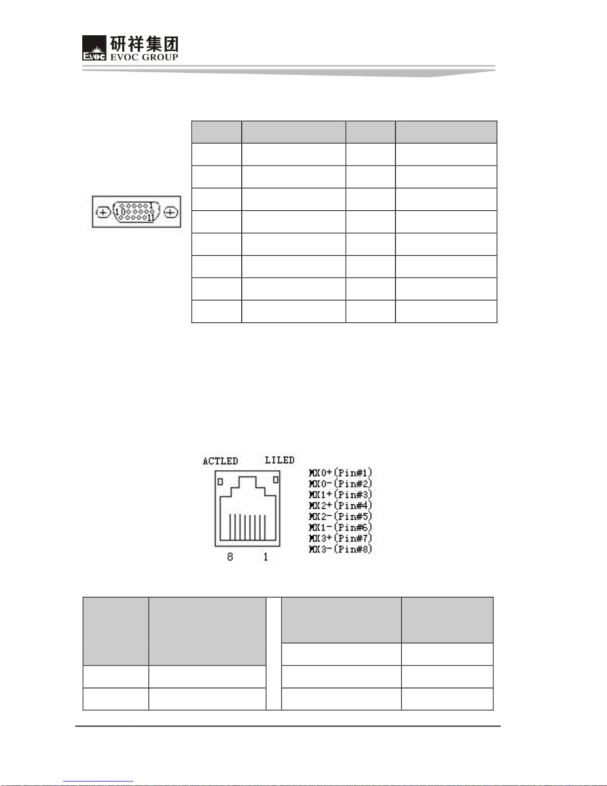
VideoConnector
15Pin DSubVGA socket,VGA1.
VGA1
Pin SignalName Pin SignalName
1 Red 2 Green
3 Blue 4 NC
5 GND 6 GND
7 GND 8 GND
9 +5V 10 GND
11 NC 12 DDCDATA
13 HSYNC 14 VSYNC
15 DDCCLK
LANPort
Theboardprovidestwo10/100/1000MbpsEthernetports;LILED andACTLEDare
the two LED indicators beside Ethernet ports, which respectively show the activity
andtransmittingstatusofLAN.PleaserefertothestatusdescriptionsforeachLED:
LAN1/LAN2
ACTLED
(Green)
LANActivity
Indicator
LILED
(DualColor:Y/G)
LANSpeed
Indicator
Green 1000Mbps
Blink DataTransmitting Yellow 100Mbps
Off NoDatatoTransmit Off 10Mbps

Chapter2Installation
EPE1814V2NAR 9
SerialPort
The board provides two 2×5Pin serial ports (Pin Distance:2.54 mm), they support
RS232modesandthepindefinitionsareasfollows:
COM1/2
Pin SignalName Pin SignalName
1 DCD# 6 DSR#
2 RXD 7 RTS#
3 TXD 8 CTS#
4 DTR# 9 RI#
5 GND 10 NA
ParallelPort
The board provides one standard 2×13Pin parallel port (Pin Distance:2.54 mm), it
could connect with peripheral devices with parallel port according to requirements.
Thepindefinitionsareasfollows:
LPT1
Pin SignalName Pin SignalName
1 STB# 2 AFD#
3 PD0 4 ERR#
5 PD1 6 INIT#
7 PD2 8 SLIN#
9 PD3 10 GND
11 PD4 12 GND
13 PD5 14 GND
15 PD6 16 GND
17 PD7 18 GND
19 ACK# 20 GND
21 BUSY 22 GND
23 PE 24 GND
25 SLCT 26 NC
Chapter 2 Installation
10 EPE1814V2NAR
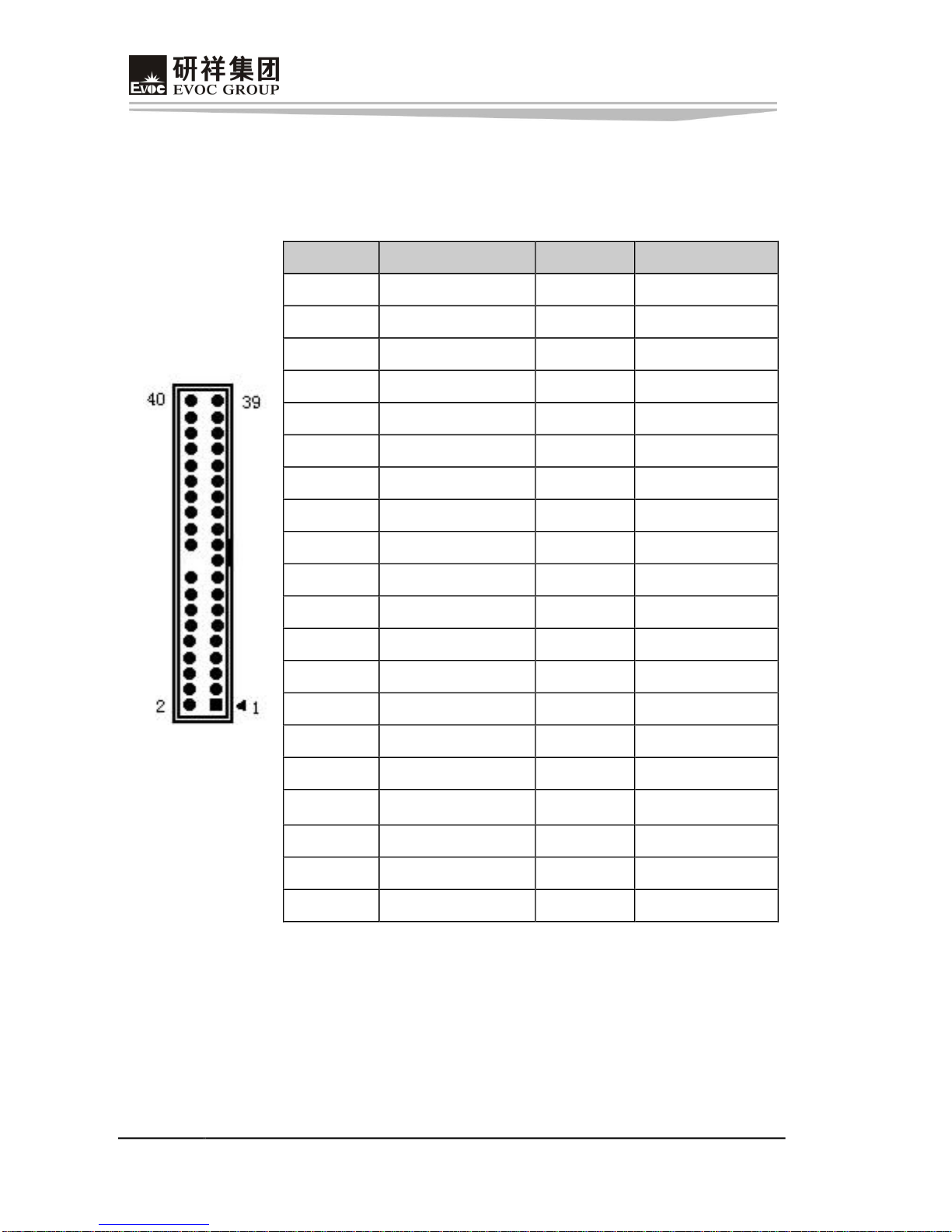
IDEConnector
Theboardprovidesonestandard2×20PinIDEconnector(PinDistance:2.54mm),it
supports Ultra100/66/33BMIDEand PIOmode.Thepindefinitionsareasfollows:
IDE1
Pin SignalName Pin SignalName
1 RESET# 2 GND
3 D7 4 D8
5 D6 6 D9
7 D5 8 D10
9 D4 10 D11
11 D3 12 D12
13 D2 14 D13
15 D1 16 D14
17 D0 18 D15
19 GND 20 Key
21 DREQ 22 GND
23 IOW# 24 GND
25 IOR# 26 GND
27 IORDY 28 GND
29 DACK# 30 GND
31 IRQ 32 NC
33 DA1 34 ATA66_DET
35 DA0 36 DA2
37 CS1# 38 CS3#
39 LED# 40 GND

Chapter2Installation
EPE1814V2NAR 11
SATA Connector
TheboardsupportsfourSATAconnectors,twoofwhichareeducedviacarrier.The
pindefinitionsofthetwostandardconnectorsonmotherboardarelistedasfollows:
SATA1/2
Pin SignalName
1 GND
2 TX+
3 TX
4 GND
5 RX
6 RX+
7 GND
Hotswapof SATA HardDisk
NoticesforHotswapofSATAHardDisk:
1. The hard diskshall support SATA 2.0 and use 15pin SATA hard disk power
connector.
2. Thedriverofchipsetshallsupportthehotswapof SATAharddisk.
3. HotswapofSATAharddiskwiththeoperatingsystemisforbidden whensystem
ispoweron.
Pleasecarryouthotplugasfollows,improperoperationmaydestroytheharddiskor
resultindatalost.
HotPlug
SATA DataCable SATA PowerCable

Chapter 2 Installation
12 EPE1814V2NAR
Step1:Pleaseplugthe1x4pinSATApowerconnector(white)intothepoweradapter.
Step2:PleaseconnecttheSATAdatacabletotheSATA connectorontheboard.
Step3:Pleaseconnectthe15pinSATApowerconnector(black)totheSATAharddisk.
Step4:PleaseconnecttheSATAdatacabletotheSATAharddisk.

Chapter2Installation
EPE1814V2NAR 13
HotUnplug
Step1:uninstalltheharddiskfromthedevicemanager.
Step2:UnplugthedatacablefromtheSATAharddisk.
Step3:Unplug theSATA15pinpower connector(black)fromtheSATAharddisk.
USBPort
The board supports eight USB ports, four of whichare educed out via carrier. The
boardprovidestwosetsofstandardUSBports(PinDistance: 2.54mm),whichcould
educeoutfourUSBports. Thepin definitions areasfollows:
USB1/2
Pin SignalName Pin SignalName
1 +5V 2 +5V
3 USB1_Data 4 USB2_Data
5 USB1_Data+ 6 USB2_Data+
7 GND 8 GND
9 NA 10 GND

Chapter 2 Installation
14 EPE1814V2NAR
DigitalIOConnector
Theboardprovidesone8bitdigitalI/Oconnector(PinDistance:2.00mm);thepin
definitionsareasfollows:
GPIO1
Pin SignalName Pin SignalName
1 DIO_IN0 2 DIO_OUT0
3 DIO_IN1 4 DIO_OUT1
5 DIO_IN2 6 DIO_OUT2
7 DIO_IN3 8 DIO_OUT3
9 GND 10 NC
KeyboardandMouseConnector
Keyboardandmouseconnector
KM1
Pin SignalName
1 KB_DATA
2 MS_DATA
3 GND
4 +5V
5 KB_CLK
6 MS_CLK
StatusIndicatingandControllingConnectors
FP1,FP2andFP3areusedtoconnectwiththefunctionbuttonorindicatorsonfront
panelofthechassis.
ATXPowerSwitchandHardDiskIndicatorConnector (PinDistance:2.54mm)
FP1
Pin SignalName Pin SignalName
1 PWRBTN# 2 GND
3 GND 4 RESET#
5 HDD_LED 6 HDD_LED+

Chapter2Installation
EPE1814V2NAR 15
PowerIndicatorConnector (PinDistance: 2.54mm)
FP2
Pin SignalName
1 PWR_LED+
2 NC
3 GND
LoudspeakerOutputConnector (PinDistance: 2.54mm)
FP3
Pin SignalName
1 SPEAKER
2 NC
3 GND
4 +5V
PowerConnector
+12V PowerConnector(PinDistance: 4.20 mm)
PWR1
Pin SignalName
1 GND
2 GND
3 +12V
4 +12V
FanConnector
TheCPUcard provides twosetsofstandardfan sockets(PinDistance: 2.50mm).Pay
attentionasfollowingthreeissueswhenusingthefan sockets:
Ø Thecurrentforfanshallnotbeover700 mA(12V);
Ø Please confirm thatthe fan cable complies withthe socket cable.Power cable
(usually red) is in the middle position. In addition, please confirm the earth

Chapter 2 Installation
16 EPE1814V2NAR
cable (usually black)and fanspeedoutputimpulsesignal cable (other colors).
Somefanshavenospeeddetectingwhiletheoutputofthecableisupto12V,
usage of these substandard connection will destroy the CPU card. It is
recommendedtouseafanwith speeddetection.
Ø Adjustthefan’sairflowtothedirectionofheatventing.
CPUFAN1/SYSFAN1
Pin SignalName
1 GND
2 +12V
3 FAN_IO
4 FAN_PWM
FAN_IO:FanSpeedImpulseOutput; FAN_PWM:FanSpeed PWM Control
InstalltheCPU
PleaseinstalltheCPUasfollows(Refertothefigurebelow):
Ø AimtheconcaveoftheCPUattheheavemarkontheCPUsocket;thenputthe
CPUinthesocket;
Ø After the CPUisinstalled properly, cover the CPU via the upper cover of the
CPUsocket;thenfastentheCPUwithhooks.
InstalltheCPUCoolingFan
PleaseinstalltheCPU cooling fanasfollows(Refertothefigurebelow):
Ø Firstly,aimthebracketofthecoolingfin(seefigure ④)atthefixingholeson
Table of contents
Other EVOC Motherboard manuals

EVOC
EVOC EC3-1820V2NA User manual

EVOC
EVOC NET-1821VD2N User manual

EVOC
EVOC EC7-1813CLD2NA SERIES User manual

EVOC
EVOC ec3-1813cld2na User manual

EVOC
EVOC EC7-1818CLD2NA User manual

EVOC
EVOC CPC-3813CLD3N User manual

EVOC
EVOC 104-1649CLD2NA Series User manual

EVOC
EVOC EC0-1814 User manual

EVOC
EVOC EC3-1813 Series User manual

EVOC
EVOC EC0-1818-C236 User manual


 manual ")


